EP0629039A1 - Übergangssignale diskriminierender Signalgenerator für Oberwellensignale - Google Patents
Übergangssignale diskriminierender Signalgenerator für Oberwellensignale Download PDFInfo
- Publication number
- EP0629039A1 EP0629039A1 EP94108698A EP94108698A EP0629039A1 EP 0629039 A1 EP0629039 A1 EP 0629039A1 EP 94108698 A EP94108698 A EP 94108698A EP 94108698 A EP94108698 A EP 94108698A EP 0629039 A1 EP0629039 A1 EP 0629039A1
- Authority
- EP
- European Patent Office
- Prior art keywords
- harmonics
- input signal
- circuit
- producing
- generator
- Prior art date
- Legal status (The legal status is an assumption and is not a legal conclusion. Google has not performed a legal analysis and makes no representation as to the accuracy of the status listed.)
- Granted
Links
- 230000001052 transient effect Effects 0.000 title claims abstract description 47
- 230000001105 regulatory effect Effects 0.000 claims abstract description 4
- 239000003990 capacitor Substances 0.000 claims description 45
- 238000000034 method Methods 0.000 claims description 2
- 241000269627 Amphiuma means Species 0.000 claims 1
- 230000009977 dual effect Effects 0.000 description 24
- 238000010586 diagram Methods 0.000 description 13
- 230000000694 effects Effects 0.000 description 5
- 238000012546 transfer Methods 0.000 description 4
- 229910000831 Steel Inorganic materials 0.000 description 2
- 230000035559 beat frequency Effects 0.000 description 2
- 230000006835 compression Effects 0.000 description 2
- 238000007906 compression Methods 0.000 description 2
- 230000005284 excitation Effects 0.000 description 2
- 238000012986 modification Methods 0.000 description 2
- 230000004048 modification Effects 0.000 description 2
- 238000012545 processing Methods 0.000 description 2
- 239000010959 steel Substances 0.000 description 2
- 229910001369 Brass Inorganic materials 0.000 description 1
- SUYHYHLFUHHVJQ-UHFFFAOYSA-N Menazon Chemical compound COP(=S)(OC)SCC1=NC(N)=NC(N)=N1 SUYHYHLFUHHVJQ-UHFFFAOYSA-N 0.000 description 1
- 230000009471 action Effects 0.000 description 1
- 238000013459 approach Methods 0.000 description 1
- 239000010951 brass Substances 0.000 description 1
- 230000002708 enhancing effect Effects 0.000 description 1
- 229920001821 foam rubber Polymers 0.000 description 1
- 230000006872 improvement Effects 0.000 description 1
- 230000000284 resting effect Effects 0.000 description 1
- 230000002441 reversible effect Effects 0.000 description 1
- 230000000630 rising effect Effects 0.000 description 1
- 238000007493 shaping process Methods 0.000 description 1
- 230000005236 sound signal Effects 0.000 description 1
- 230000002459 sustained effect Effects 0.000 description 1
Images

Classifications
-
- H—ELECTRICITY
- H03—ELECTRONIC CIRCUITRY
- H03B—GENERATION OF OSCILLATIONS, DIRECTLY OR BY FREQUENCY-CHANGING, BY CIRCUITS EMPLOYING ACTIVE ELEMENTS WHICH OPERATE IN A NON-SWITCHING MANNER; GENERATION OF NOISE BY SUCH CIRCUITS
- H03B19/00—Generation of oscillations by non-regenerative frequency multiplication or division of a signal from a separate source
- H03B19/16—Generation of oscillations by non-regenerative frequency multiplication or division of a signal from a separate source using uncontrolled rectifying devices, e.g. rectifying diodes or Schottky diodes
-
- G—PHYSICS
- G10—MUSICAL INSTRUMENTS; ACOUSTICS
- G10H—ELECTROPHONIC MUSICAL INSTRUMENTS; INSTRUMENTS IN WHICH THE TONES ARE GENERATED BY ELECTROMECHANICAL MEANS OR ELECTRONIC GENERATORS, OR IN WHICH THE TONES ARE SYNTHESISED FROM A DATA STORE
- G10H1/00—Details of electrophonic musical instruments
- G10H1/02—Means for controlling the tone frequencies, e.g. attack or decay; Means for producing special musical effects, e.g. vibratos or glissandos
- G10H1/06—Circuits for establishing the harmonic content of tones, or other arrangements for changing the tone colour
- G10H1/16—Circuits for establishing the harmonic content of tones, or other arrangements for changing the tone colour by non-linear elements
-
- G—PHYSICS
- G10—MUSICAL INSTRUMENTS; ACOUSTICS
- G10H—ELECTROPHONIC MUSICAL INSTRUMENTS; INSTRUMENTS IN WHICH THE TONES ARE GENERATED BY ELECTROMECHANICAL MEANS OR ELECTRONIC GENERATORS, OR IN WHICH THE TONES ARE SYNTHESISED FROM A DATA STORE
- G10H2230/00—General physical, ergonomic or hardware implementation of electrophonic musical tools or instruments, e.g. shape or architecture
- G10H2230/045—Special instrument [spint], i.e. mimicking the ergonomy, shape, sound or other characteristic of a specific acoustic musical instrument category
- G10H2230/251—Spint percussion, i.e. mimicking percussion instruments; Electrophonic musical instruments with percussion instrument features; Electrophonic aspects of acoustic percussion instruments or MIDI-like control therefor
- G10H2230/271—Spint gong, i.e. mimicking circular flat, nippled or bowl-shaped metallic percussion instruments
Definitions
- the present invention generally relates to the field of electronic audio equipment. More particularly, the present invention relates to the field of harmonics generators.
- Harmonics generators are widely used in various applications of audio signal processing utilized for creating musical sound effects and enhancing sound quality.
- a product made by Aphex Systems Ltd. called an "Aural Exciter" under United States Patent No. 4,150,253 is based partly upon the use of a harmonics generator.
- a harmonics generator can be defined as a device which is used intentionally to produce harmonics of an input signal. Such a device may also produce spurious frequencies, for example beat frequencies, without violating the definition of a harmonics generator.
- a simple harmonics generator can be comprised of a full-wave rectifier circuit. The output signal from a full wave rectifier contains not only harmonics of the input signal, but also beat frequencies if the input signal is composed of typical audio waveforms which are composed of many frequency components.
- non-linear circuits such as log amplifiers, rectifiers and multipliers are used as harmonics generators. These circuits all follow different harmonics generation laws depending on their input-output transfer functions.
- the amplitude of the harmonics in the output signal is mainly a function of the input signal amplitude without regard to time.
- the harmonics which are developed resemble merely disortion products of the input signal.
- the usability of prior art harmonics generators for sound enhancement and music is therefore limited because the harmonics produced do not generally resemble harmonics of natural sounds and thus, are not pleasing to the human ear.
- harmonics generator that can generate harmonics which is not only a function of the amplitude of the input signal, but also a function of the time, to thereby better resemble the harmonics of natural sounds for sound enhancement and music.
- the present invention is a transient discriminate harmonics generator.
- the present invention generates harmonics with a time and amplitude relationship that more closely resembles the harmonics of natural sounds.
- the present invention can be better understood by modeling a natural event as follows.
- natural harmonics are created by striking a brass gong with a steel hammer.
- the sound of the gong is extremely rich in harmonic content.
- the relative level of the harmonics decays at a higher rate than the level of basic note frequency, i.e., the fundamental frequency.
- the sound decays to a pure tone devoid of harmonics.
- the steel hammer strike represents a transient excitation force having a steeply rising wavefront.
- the relative amount of harmonics in the sound will be much less, and the tone of the gong will be closer to a pure note.
- the amount of harmonics in the sound depends on how sharply the gong is struck.
- the harmonics decays out sooner than the fundamental tone.
- a novel and unique harmonics generator which produces a higher level of harmonics at the beginning of a transient event of the input signal, and a lower level of harmonics following the transient event.
- the present invention harmonics generator produces relatively low level harmonics in the output signal upon steady, non transient input signals. This produces a harmonics effect more pleasing to the ear and therefore is more usable in music and sound enhancement than the harmonics generated by prior art harmonics generators.
- the present invention transient descriminate harmonics generator for generating harmonics of an input signal comprises (a) a resistor-capacitor circuit for setting a time constant having a first end for receiving the input signal and a second end, the resistor-capacitor circuit including a capacitor and a first resistor connected in parallel between the first and second ends; (b) a diode having an anode and a cathode connected to the second end of the resistor-capacitor circuit for rectifying the input signal; (c) a negative power source for supplying a negative voltage to the cathode of the diode through a resistor circuit which includes a second resistor connected between the negative power source and the cathode of the diode; (d) a current-voltage convertor connected to the anode of the diode for producing an output signal containing harmonics of the input signal, the current-voltage converter including an operational amplifier having a positive input pin, a negative input pin and an output pin
- the transient discriminate harmonics generator for generating harmonics of an input signal can also comprise (a) a resistor-capacitor circuit for setting a time constant having a first end for receiving said input signal and a second end, the resistor-capacitor circuit including a capacitor and a first resistor connected in parallel between the first and second ends; (b) a diode having an anode and a cathode connected to said second end of said resistor-capacitor circuit for rectifying said input signal; (c) a negative power source for supplying a negative voltage to said cathode of said diode through a resistor circuit which includes a second resistor connected between the negative power source and said cathode of said diode; (d) a current-voltage converter connected to said anode of said diode for producing an output signal containing harmonics of said input signal, the current-voltage convertor including an operational amplifier having a positive input pin, a negative input pin and an output pin, a third resistor connected between said
- said capacitor can preferably be 0.1 ⁇ F and/or said first resistor can preferably be 270K ⁇ .
- said second resistor can preferably be 2.2M ⁇ and/or said third resistor can preferably be 4.7K ⁇ .
- said fourth resistor can preferably be 10K ⁇ and/or said negative power source can preferably be -15V.
- a transient discriminate harmonics generator comprises a resistor-capacitor circuit for setting a time constant and a diode rectifying circuit for producing an output signal containing harmonics of an input signal, the harmonics generator being capable of producing a relatively high level of harmonics at an initial occurrence of the input signal, and incrementally reducing the level of harmonics generated during a time period determined by the time constant following the initial occurrence of the input signal, and producing a relatively low level of harmonics after said time period.
- Said diode rectifying circuit includes perferably a diode for rectifying said input signal and an operational amplifier used as a current-voltage converter. Further, a negative power source for supplying a negative voltage to said cathode of said diode through a resistor circuit is preferably provided.
- the present invention transient discriminate harmonics generator for generating harmonics of an input signal comprises: (a) a multiplier circuit for producing an output signal, the multiplier circuit having an X-channel and a Y-channel, and the output signal being proportional to a product of an X-channel input signal and a Y-channel input signal; (b) an automatic gain control circuit for producing a control signal to modulate the multiplier circuit, the automatic gain control circuit having an input end and an output end and a variable resister circuit for adjusting the control signal; (c) the multiplier circuit and the automatic gain control circuit utilizing a dual operational transconductance amplifier chip, where the automatic gain control circuit uses one functional half of the dual operational transconductance amplifier chip, and the multiplier circuit uses another functional half of the dual operational transconductance amplifier chip; (d) the Y-channel of the multiplier circuit and the input end of the automatic gain control circuit being connected together to receive the input signal; (e) the input end of the automatic gain control circuit further including a
- a transient discriminate harmonics generator for generating harmonics of an input signal, comprises (a) a multiplier circuit for producing an output signal, the multiplier circuit having an X-channel and a Y-channel, and the output signal being proportional to a product of an X-channel input signal and a Y-channel input signal; (b) an automatic gain control circuit for producing a control signal to modulate said multiplier circuit, the automatic gain control circuit having an input end and an output end; (c) said Y-channel of said multiplier circuit and said input end of said automatic gain control circuit being connected together to receive said input signal; (d) said output end of said automatic gain control circuit being connected to said X-channel of said multiplier circuit, such that said output signal of said multiplier circuit contains harmonics which are proportional to the product of said input signal and said control signal from said automatic gain control circuit; and (e) said harmonics generator being capable of producing a relatively high level of harmonics at an initial occurrence of said input signal, and incrementally reducing the level of harmonics generated during a time
- said multiplier circuit and said automatic gain control circuit utilize preferably a dual operational transconductance amplifier chip, where said automatic gain control circuit uses one functional half of the dual operational transconductance amplifier chip, and said multiplier circuit uses another functional half of the dual operational transconductance amplifier chip.
- Said input end of said automatic gain control circuit includes preferably a resistor-capacitor circuit for setting a time constant which determines said time period during which said level of harmonics is incrementally reduced. Further, said output end of said automatic gain control circuit utilizes preferably a Darlinton part of said dual operational transconductance amplifier chip.
- Said automatic gain control circuit includes perferably a variable resistor circuit for adjusting said control signal which is output from said automatic gain control circuit to said multiplier circuit.
- Said generator further comprises a positive voltage source and a negative voltage source for energizing said automatic gain control circuit and said multiplier circuit.
- the transient discriminate harmonics generator for generating harmonics of an input signal can also comprise (a) a multiplier circuit for producing an output signal, the multiplier circuit having an X-channel and a Y-channel, and the output signal being proportional to a product of an X-channel input signal and a Y-channel input signal; (b) an automatic gain control circuit for producing a control signal to modulate said multiplier circuit, the automatic gain control circuit having an input end and an output end and a variable resistor circuit for adjusting the control signal; (c) said multiplier circuit and said automatic gain control circuit utilizing a dual operational transconductance amplifier chip, where said automatic gain control circuit uses one functional half of the dual operational transconductance amplifier chip, and said mulitplier circuit uses another functional half of the dual operational transconductance amplifier chip; (d) said Y-channel of said multiplier circuit and said input end of said automatic gain control circuit being connected together to receive said input signal; (e) said input end of said automatic gain control circuit further including a resistor-capacit
- said power source includes preferably a positive voltage source and a negative voltage source for energizing said automatic gain control circuit and said multiplier circuit.
- Said variable resistor circuit of said automatic gain control circuit includes preferably a first variable resistor of 25K ⁇ .
- said variable resistor circuit of said automatic gain control circuit includes preferably a second variable resistor connected between said positive and negative voltage sources for providing an adjustable working current to said dual operational transconductance amplifier chip.
- said multiplier includes preferably a capacitor connected between said input end of said automatic gain control circuit and said Y-channel of said multiplier circuit for isolating any direct current (DC) component of said input signal.
- a transient discriminate harmonics generator comprises a harmonics generating circuit for producing an output signal containing harmonics of an input signal, and an automatic gain control circuit connected to a gain control input of the harmonics generating circuit and producing a control signal to modulate said harmonics generating circuit, the harmonics generator being capable of producing a relatively high level of harmonics at an initial occurrence of the input signal, and incrementally reducing the level of harmonics generated during a time period determined by the control signal following the initial occurrence of the input signal, and producing a relatively low level of harmonics after said time period.
- Said harmonics generating circuit and said automatic gain control circuit utilize preferably a dual operational transconductance amplifier chip, where said automatic gain control circuit uses one functional half of the dual operational transconductance amplifier chip, and said harmonics generating circuit uses another functional half of the dual operational transconductance amplifier chip.
- said automatic gain control circuit includes preferably a resistor-capacitor circuit for setting a time constant which determines said time period during which said level of harmonics is incrementally reduced.
- Said automatic gain control circuit includes preferably a variable resister circuit for adjusting said control signal which is output from said automatic gain control circuit to said harmonics generating circuit. Further a power source for energizing said automatic gain control circuit and said harmonics generating circuit is provided for said generator.
- a transient discriminate harmonics generator comprises (a) means for receiving an input signal coupled to a harmonics generating circuit; (b) said harmonics generating circuit being capable of producing an output signal containing harmonics of said input signal; (c) said harmonics generator generating a relatively high level of harmonics at an initial occurrence of said input signal; (d) said harmonics generator incrementally reducing the level of harmonics generated during a time period following the initial occurrence of said input signal; and (e) said harmonics generator producing a relatively low level of harmonics after the end of said time period.
- said harmonic generating circuit is preferably a diode rectifying circuit.
- Said harmonic generating circuit is preferably a linear multiplier circuit.
- said harmonic generating circuit is preferably a voltage control amplifier circuit.
- a transient discriminate harmonics generator comprises a control circuit for determining a control parameter, and a harmonics generating circuit regulated by the control circuit for producing an output signal containing harmonics of an input signal, where the transient discriminate harmonics generator first generates a relatively high level of harmonics at an initial occurrence of the input signal, then incrementally reduces the level of harmonics generated during a time period determined by the control parameter following the initial occurrence of the input signal, and finally produces a relatively low level of harmonics after the end of the time period.
- said harmonic generating circuit is preferably a diode rectifying circuit.
- Said harmonic generating circuit is preferably a linear multiplier circuit.
- said harmonic generating circuit is preferably a voltage control amplifier circuit.
- Said control circuit is preferably a resistor-capacitor circuit.
- Said control circuit is preferably an automatic gain control circuit.
- a method for generating transient discriminate harmonics consists in the fact that a higher level of harmonics at the beginning of a transient event of an input signal is produced and a lower level of harmonics follows the transient event.
- FIG. 1 a schematic diagram of one of the preferred embodiments of the present invention showing a transient discriminate harmonics generator utilizing a diode rectifier.
- An input signal is supplied at point 10.
- the input signal at point 10 may be sourced from a low impedance such as an operational amplifier output, and the input signal may represent an AC audio waveform resting on zero volts DC.
- Resistor R1 and capacitor C1 serve as a time constant circuit as will be described.
- resistor R1 may be 270K ⁇
- capacitor C1 may be 0.1 ⁇ F.
- a negative voltage -E is provided at point 60, where a resistor R2 is used to conduct a small negative current into diode D1 from the negative voltage -E.
- the negative voltage -E may be -15V
- resistor R2 may be 2.2M ⁇
- Operational amplifier U1 is configured with resistors R3 and R4 as a current-voltage converter.
- resitor R3 may be 4.7K ⁇
- resistor R4 may be 10K ⁇ .
- diode D1 Since diode D1 is oriented to pass only a negative current to resistor R3, an output at point 50 will only be present when a negative current flows, i.e., there will never be a positive current into resistor R3. This produces a rectification effect for AC voltage appearing at point 20 of the circuit.
- the rectification effect produces a positive polarity half-wave output signal at point 50 representing the negative polarity half waves of the AC signal of point 20.
- This output signal contains harmonics of the input signal.
- diode D1 When an input tone is suddenly supplied as the input signal to point 10, during the first few cycles of the tone, diode D1 conducts current from the negative half cycles and produces a positive polarity output at point 50. Each half cycle of conduction through diode D1 into resistor R3 charges up capacitor C1 a little further.
- the charging time of capacitor C1 is a function of the resistor-capacitor (R3-C1) time constant. As capacitor C1 begins to charge, a positive DC voltage begins to develop at point 20 relative to point 10. Since point 10 is held near DC ground potential by the signal source, the DC charge appears as a positive bias to the cathode of diode D1 reversing the forward bias supplied by resistor R2, and taking diode D1 towards the reverse biased condition.
- the amplitude of the harmonic output signal shown in Figure 2(b) is greater at the first instance of applying the input signal, and diminishes or "ramps down" to a smaller level. This may be called the "attack" parameter of the harmonics generator 5.
- the attack time constant should be chosen for optimal sonic benefits in a particular application.
- the time constant of resistor R3 and capacitor C1 determine the slope of the attack parameter.
- Resistor R1 serves the purpose mainly of providing a suitable discharge path for C1 after the input signal is removed.
- the present invention illustrated in Figure 1 utilizes a diode rectifier in the harmonics generator circuit.
- the present invention is not limited to any specific means of creating harmonics, as long as the shaping of the output harmonics is enforced.
- the present invention may also utilize a multiplier in its circuit.
- harmonics generator circuit 95 may be a linear multiplier having a transfer function of (XY)/K. It could also be any variety of voltage control amplifiers (VCAs) with a signal input, signal output and gain control input. If a VCA is utilized, it can be defined as an XY multiplier if we call the signal input the "Y" channel input and the gain control input the "X" channel input.
- VCA voltage control amplifier
- multiplier 130 When multiplier 130 is a linear multiplier, its output function is (XY)/K, when X is the signal at X input, and Y is the signal at Y input, and K is a constant. If the X and Y inputs are fed an equal signal, i.e., the automatic gain control (AGC) circuit 110 is removed, then the multiplier output at point 150 would be y2/K and would represent a typical circuit of prior art harmonics generators. If the input signal is sinusoidal, this translates to sin2/K which contains a frequency which is the second harmonic of the input signal. As discussed before, the harmonics output resembles merely the distortion products of the input signal, and the usability of such prior art harmonics generator for sound enhancement and music is limited because the harmonics produced do not generally resemble harmonics of natural sounds.
- AGC automatic gain control
- the addition of the AGC circuit 110 greatly changes the character of the multiplier harmonics generator.
- the parameters of the AGC circuit 110 such as specific compression ratio, attack and release times of the AGC, are to be determined for best effect in a particular application. Nonetheless, the attack time is required to be of a finite value.
- the AGC circuit 110 may have an infinite compression ratio, an attack time of about 20ms, and a threshold 10dB below the input signal level.
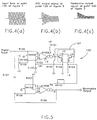
- FIGS. 4(a), 4(b) and 4(c) there are shown respectively the waveform of the input signal at point 100 which is also the Y input of the multiplier 130, the waveform expected at the AGC output point 120 which is also the X input of the multiplier 130, and the waveform of the multiplier harmonics output at point 140.
- the AGC circuit 110 produces an initial output overshoot during the AGC attack time. This AGC overshoot results in a shaped harmonics from the mulitplier 130 by producing a greater XY product during the overshoot period and a lesser XY product after the AGC output level is stable.
- the harmonics generator circuit 195 includes two functional circuits: a multiplier circuit and an AGC circuit.
- the two circuits are based on an LM13700 dual operational transconductance amplifier (OTA) chip, which is used as a multiplier with one half U100B, and an AGC amplifier with the other half U100A.
- OTA operational transconductance amplifier
- the pin numbers shown thereon (1 through 16) are the pin numbers of the LM13700 dual OTA chip.
- the multiplier circuit also includes capacitor C101, resistors R106, R107 and R108, and variable resistors VR101 and VR102.
- capacitor C101 may be 22 ⁇ F
- resistors R106 and 107 may be 10K ⁇
- resistor R108 may be 5K ⁇
- variable resistor VF101 may be 50K ⁇
- variable resistor VR102 may be 1K ⁇ .
- the AGC circuit also includes capacitor C100, resistors R100, R101, R102, R103, R104, R105 and R109, and variable resistors VF100 and VR103.
- the dotted block 197 is the Darlingtons part of the LM13700 dual OTA chip, which is used not to buffer the output of the multiplier, but rather to buffer the output of the AGC amplifier.
- capacitor C100 may be 4.7 ⁇ F
- resistor R100 may be 250K
- resistor R101 may be 30K ⁇
- resistors R102, R103 and R104 may be 10K ⁇
- resistor R105 may be 100K ⁇
- resistor R109 may be 10M ⁇
- variable resistor VR100 may be 25K ⁇
- variable resistor VR103 may be 50K ⁇ .
- the improvement in the circuitry element utilizing the LM13700 dual OTA chip involves the following circuit components. Variable resistors VR103 and R109 have been added to allow better nulling of the control feedthrough of the AGC amplifier.
- Capacitor C101 has been added to isolate the DC input offset voltage of the multiplier circuit.
- positive voltage +E and negative voltage -E are provided to the circuit.
- the positive voltage +E may be 15V and the negative voltage -E may be -15V.
- the harmonics generator circuit 195 operates as follows.
- the AGC circuit 110 shown in Figure 3 is provided by the circuit of U100A.
- the AGC output at point 120 of Figure 3 is equivalent to the output at pin 9 of the LM13700 second Darlingtons transistor.
- the multiplier 130 shown in Figure 3 is provided by the circuit of U100B.
- the X input of Figure 3 is translated as a current input at pin 16 of U100B by the input resistance of variable resistor VR101.
- the Y input of Figure 3 is represented as the signal input to resistor R100.
- the AGC input of Figure 3 is represented as the signal input to capacitor C101.
- the harmonics output at point 140 of Figure 3 is equivalent to the U100B pin 12 output. It is noted that this is a high impedance output and must not be significantly loaded by any external impedances for correct operation.
- circuit shown in Figure 5 is not intended as a limitation to the embodiment of the present invention transient discriminate harmonics generator. It has been shown how the present invention can be implemented in numerous ways. There are undoubtedly many more circuits including various means of generating harmonics which can be adapted to follow the teachings of the present invention. Therefore, the present invention is not limited to the examples which were shown here. In addition, the teachings of the present invention can be implemented in digital signal processing with equal validity.
- the present invention is a transient discriminate harmonics generator for generating harmonics of an input signal, comprising: (a) a resistor-capacitor circuit for setting a time constant having a first end for receiving said input signal and a second end, the resistor, capacitor circuit including a capacitor and a first resistor connected in parallel between the first and second ends; (b) a diode having an anode and a cathode connected to said second end of said resistor-capacitor circuit for rectifying said input signal; (c) a negative power source for supplying a negative voltage to said cathode of said diode through a resistor circuit which includes a second resistor connected between the negative power source and said cathode of said diode; (d) a current-voltage converter connected to said anode of said diode for producing an output signal containing harmonics of said input signal, the current-voltage convertor including an operational amplifier having a positive input pin, a negative input pin and an output pin,
- the present invention is a transient discriminate harmonics generator for generating harmonics of an input signal, comprising: (a) a resistor-capacitor circuit for setting a time constant having a first end for receiving said input signal and a second end; (b) a diode having an anode and a cathode connected to said second end of said resistor-capacitor circuit for rectifying said input signal; (c) a negative power source for supplying a negative voltage to said cathode of said diode through a resistor circuit; (d) a current-voltage converter connected to said anode of said diode for producing an output signal containing harmonics of said input signal; and (e) said harmonics generator being capable of producing a relatively high level of harmonics at an initial occurrence of said input signal, and incrementally reducing the level of harmonics generated during a time period determined by said time constant following the initial occurrence of said input signal, and producing a relatively low level of harmonics after said time period.
- the present invention is a transient descriminate harmonics generator comprising a resistor-capacitor circuit for setting a time constant and a diode rectifying circuit for producing an output signal containing harmonics of an input signal, the harmonics generator being capable of producing a relatively high level of harmonics at an initial occurrence of the input signal, and incrementally reducing the level of harmonics generated during a time period determined by the time constant following the initial occurrence of the input signal, and producing a relatively low level of harmonics after said time period.
- the present invention is a transient discriminate harmonics generator for generating harmonics of an input signal, comprising: (a) a multiplier circuit for producing an output signal, the multiplier circuit having an X-channel and a Y-channel, and the output signal being proportional to a product of an X-channel input signal and a Y-channel input signal; (b) an automatic gain control circuit for producing a control signal to modulate said multiplier circuit, the automatic gain control circuit having an input end and an output end and a variable resister circuit for adjusting the control signal; (c) said multiplier circuit and said automatic gain control circuit utilizing a dual operational transconductance amplifier chip, where said automatic gain control circuit uses one functional half of the dual operational transconductance amplifier chip, and said multiplier circuit uses another functional half of the dual operational transconductance amplifier chip; (d) said Y-channel of said multiplier circuit and said input end of said automatic gain control circuit being connected together to receive said input signal; (e) said input end of said automatic gain control circuit
- the present invention is a transient discriminate harmonics generator for generating harmonics of an input signal, comprising: (a) a multiplier circuit for producing an output signal, the multiplier circuit having an X-channel and a Y-channel, and the output signal being proportional to a product of an X-channel input signal and a Y-channel input signal; (b) an automatic gain control circuit for producing a control signal to modulate siad multiplier circuit, the automatic gain control circuit having an input end and an output end; (c) said Y-channel of said multiplier circuit and said input end of said automatic gain control circuit being connected together to receive said input signal; (d) said output end of said automatic gain control circuit being connected to said X-channel of said multiplier circuit, such that said output signal of said multiplier circuit contains harmonics which are proportional to the product of said input signal and said control signal from said automatic gain control circuit; and (e) said harmonics generator being capable of producing a relatively high level of harmonics at an initial occurrence of said input signal
- the present invention is a transient discriminate harmonics generator comprising a harmonics generating circuit for producing an output signal containing harmonics of an input signal, and an automatic gain control circuit connected to a gain control input of the harmonics generating circuit and producing a control signal to modulate said harmonics generating circuit, the harmonics generator being capable of producing a relatively high level of harmonics at an initial occurrence of the input signal, and incrementally reducing the level of harmonics generated during a time period determined by the control signal following the initial occurrence of the input signal, and producing a relatively low level of harmonics after said time period.
- the present invention is a transient discriminate harmonics generator comprising: (a) means for receiving an input signal coupled to a harmonics generating circuit; (b) said harmonics generating circuit being capable of producing an output signal containing harmonics of said input signal; (c) said harmonics generator generating a relatively high level of harmonics at an initial occurrence of said input signal; (d) said harmonics generator incrementally reducing the level of harmonics generated during a time period following the initial occurrence of said input signal; and (e) said harmonics generator producing a relatively low level of harmonics after the end of said time period.
- the present invention is a transient discriminate harmonics generator comprising a control circuit for determining a control parameter, and a harmonics generating circuit regulated by the control circuit for producing an output signal containing harmonics of an input signal, where the transient discriminate harmonics generator first generates a relatively high level of harmonics at an initial occurrence of the input signal, then incrementally reduces the level of harmonics generated during a time period determined by the control parameter following the initial occurrence of the input signal, and finally produces a relatively low level of harmonics after the end of the time period.
Landscapes
- Physics & Mathematics (AREA)
- Nonlinear Science (AREA)
- Engineering & Computer Science (AREA)
- Acoustics & Sound (AREA)
- Multimedia (AREA)
- Power Conversion In General (AREA)
- Electrophonic Musical Instruments (AREA)
- Supply And Distribution Of Alternating Current (AREA)
- Control Of Eletrric Generators (AREA)
- Rectifiers (AREA)
- Networks Using Active Elements (AREA)
Applications Claiming Priority (2)
| Application Number | Priority Date | Filing Date | Title |
|---|---|---|---|
| US72995 | 1993-06-07 | ||
| US08/072,995 US5424488A (en) | 1993-06-07 | 1993-06-07 | Transient discriminate harmonics generator |
Publications (2)
| Publication Number | Publication Date |
|---|---|
| EP0629039A1 true EP0629039A1 (de) | 1994-12-14 |
| EP0629039B1 EP0629039B1 (de) | 1999-05-19 |
Family
ID=22111047
Family Applications (1)
| Application Number | Title | Priority Date | Filing Date |
|---|---|---|---|
| EP94108698A Expired - Lifetime EP0629039B1 (de) | 1993-06-07 | 1994-06-07 | Übergangssignale diskriminierender Signalgenerator für Oberwellensignale |
Country Status (5)
| Country | Link |
|---|---|
| US (1) | US5424488A (de) |
| EP (1) | EP0629039B1 (de) |
| JP (1) | JPH07140979A (de) |
| AT (1) | ATE180363T1 (de) |
| DE (1) | DE69418530T2 (de) |
Families Citing this family (5)
| Publication number | Priority date | Publication date | Assignee | Title |
|---|---|---|---|---|
| US6023513A (en) * | 1996-01-11 | 2000-02-08 | U S West, Inc. | System and method for improving clarity of low bandwidth audio systems |
| US6335973B1 (en) | 1996-01-11 | 2002-01-01 | Qwest Communications International Inc. | System and method for improving clarity of audio systems |
| ATE458361T1 (de) * | 2005-12-13 | 2010-03-15 | Nxp Bv | Einrichtung und verfahren zum verarbeiten eines audio-datenstroms |
| US8290169B1 (en) * | 2009-12-09 | 2012-10-16 | Aphex Llc | Time shifted harmonics generator |
| US9060223B2 (en) | 2013-03-07 | 2015-06-16 | Aphex, Llc | Method and circuitry for processing audio signals |
Citations (7)
| Publication number | Priority date | Publication date | Assignee | Title |
|---|---|---|---|---|
| US3189674A (en) * | 1960-03-31 | 1965-06-15 | Nihon Gakki Seizo Kabushiki Ka | Apparatus for producing pedal sounds in electric musical instruments |
| US3321567A (en) * | 1965-10-20 | 1967-05-23 | Baldwin Co D H | Wave shaping system for electrical musical instruments |
| US4018121A (en) * | 1974-03-26 | 1977-04-19 | The Board Of Trustees Of Leland Stanford Junior University | Method of synthesizing a musical sound |
| US4044643A (en) * | 1974-01-09 | 1977-08-30 | Chase Willis E | Musical instrument circuit providing celeste and vibrato effects |
| US4175465A (en) * | 1978-05-01 | 1979-11-27 | Cbs Inc. | Circuit for simulating string bass sound |
| US4425515A (en) * | 1981-11-16 | 1984-01-10 | Hewlett-Packard Company | Method and means to minimize risetime of a microwave pulse modulated signal from a frequency multiplier circuit |
| JPH03293935A (ja) * | 1990-04-10 | 1991-12-25 | Shimadzu Corp | 充電検出装置 |
Family Cites Families (8)
| Publication number | Priority date | Publication date | Assignee | Title |
|---|---|---|---|---|
| US3495021A (en) * | 1966-06-29 | 1970-02-10 | Baldwin Co D H | Chiff and tone generator |
| JPS501748B1 (de) * | 1970-03-20 | 1975-01-21 | ||
| JPS506777B1 (de) * | 1970-12-29 | 1975-03-18 | ||
| JPS5030446B1 (de) * | 1971-03-23 | 1975-10-01 | ||
| US3937115A (en) * | 1974-08-01 | 1976-02-10 | The Wurlitzer Company | Electronic piano circuit arrangement |
| US4150253A (en) * | 1976-03-15 | 1979-04-17 | Inter-Technology Exchange Ltd. | Signal distortion circuit and method of use |
| US4198891A (en) * | 1978-04-11 | 1980-04-22 | Cbs Inc. | Circuit for simulating sounds of percussive instruments |
| US4442745A (en) * | 1980-04-28 | 1984-04-17 | Norlin Industries, Inc. | Long duration aperiodic musical waveform generator |
-
1993
- 1993-06-07 US US08/072,995 patent/US5424488A/en not_active Expired - Lifetime
-
1994
- 1994-06-06 JP JP6123645A patent/JPH07140979A/ja active Pending
- 1994-06-07 EP EP94108698A patent/EP0629039B1/de not_active Expired - Lifetime
- 1994-06-07 AT AT94108698T patent/ATE180363T1/de not_active IP Right Cessation
- 1994-06-07 DE DE69418530T patent/DE69418530T2/de not_active Expired - Lifetime
Patent Citations (7)
| Publication number | Priority date | Publication date | Assignee | Title |
|---|---|---|---|---|
| US3189674A (en) * | 1960-03-31 | 1965-06-15 | Nihon Gakki Seizo Kabushiki Ka | Apparatus for producing pedal sounds in electric musical instruments |
| US3321567A (en) * | 1965-10-20 | 1967-05-23 | Baldwin Co D H | Wave shaping system for electrical musical instruments |
| US4044643A (en) * | 1974-01-09 | 1977-08-30 | Chase Willis E | Musical instrument circuit providing celeste and vibrato effects |
| US4018121A (en) * | 1974-03-26 | 1977-04-19 | The Board Of Trustees Of Leland Stanford Junior University | Method of synthesizing a musical sound |
| US4175465A (en) * | 1978-05-01 | 1979-11-27 | Cbs Inc. | Circuit for simulating string bass sound |
| US4425515A (en) * | 1981-11-16 | 1984-01-10 | Hewlett-Packard Company | Method and means to minimize risetime of a microwave pulse modulated signal from a frequency multiplier circuit |
| JPH03293935A (ja) * | 1990-04-10 | 1991-12-25 | Shimadzu Corp | 充電検出装置 |
Non-Patent Citations (1)
| Title |
|---|
| PATENT ABSTRACTS OF JAPAN vol. 16, no. 130 (E - 1184) 2 April 1992 (1992-04-02) * |
Also Published As
| Publication number | Publication date |
|---|---|
| JPH07140979A (ja) | 1995-06-02 |
| ATE180363T1 (de) | 1999-06-15 |
| DE69418530D1 (de) | 1999-06-24 |
| EP0629039B1 (de) | 1999-05-19 |
| DE69418530T2 (de) | 2000-02-10 |
| US5424488A (en) | 1995-06-13 |
Similar Documents
| Publication | Publication Date | Title |
|---|---|---|
| US4117757A (en) | Rectangular waveform signal reproducing circuit for electronic musical instruments | |
| US10936070B2 (en) | Haptic signal generator | |
| GB1510691A (en) | Electronic singing suppressor device | |
| EP0376341A3 (de) | Vorrichtung und Verfahren zur Erzeugung von musikalischen Tonwellenformen | |
| US4263520A (en) | Signal detecting circuit for electronic musical instrument | |
| EP0629039B1 (de) | Übergangssignale diskriminierender Signalgenerator für Oberwellensignale | |
| US3465088A (en) | Musical instrument percussive keyer with variable signal decay | |
| CA2356406A1 (en) | Waveform measuring method and apparatus | |
| JPS5480114A (en) | Electronic musical instrument | |
| US4198891A (en) | Circuit for simulating sounds of percussive instruments | |
| US4175465A (en) | Circuit for simulating string bass sound | |
| US4195544A (en) | Electronic musical instrument with external sound control function | |
| JPS54128323A (en) | Waveform generating device of electronic musical instrument | |
| US3838202A (en) | Device for imparting to a musical tone a tone color varied with time | |
| JPS5481824A (en) | Electronic musical instrument | |
| US3234485A (en) | Electronic musical instrument tone generator having vibrato effect | |
| US4144581A (en) | Audio signal processor | |
| GB1506747A (en) | Electronic musical instruments | |
| US3495021A (en) | Chiff and tone generator | |
| US4177707A (en) | Electronic music synthesizer | |
| US3254336A (en) | Sound simulation system | |
| US3617604A (en) | Electronic musical instrument capable of generating musical tone signals simulating the sounds of a wind instrument | |
| US3445578A (en) | Chiff and tone generator | |
| US4205578A (en) | Electronic musical instrument signal generator | |
| US3476865A (en) | Variable time delay multivibrators |
Legal Events
| Date | Code | Title | Description |
|---|---|---|---|
| PUAI | Public reference made under article 153(3) epc to a published international application that has entered the european phase |
Free format text: ORIGINAL CODE: 0009012 |
|
| AK | Designated contracting states |
Kind code of ref document: A1 Designated state(s): AT CH DE ES FR GB IT LI NL |
|
| 17P | Request for examination filed |
Effective date: 19950420 |
|
| 17Q | First examination report despatched |
Effective date: 19970520 |
|
| GRAG | Despatch of communication of intention to grant |
Free format text: ORIGINAL CODE: EPIDOS AGRA |
|
| GRAG | Despatch of communication of intention to grant |
Free format text: ORIGINAL CODE: EPIDOS AGRA |
|
| GRAH | Despatch of communication of intention to grant a patent |
Free format text: ORIGINAL CODE: EPIDOS IGRA |
|
| GRAH | Despatch of communication of intention to grant a patent |
Free format text: ORIGINAL CODE: EPIDOS IGRA |
|
| GRAA | (expected) grant |
Free format text: ORIGINAL CODE: 0009210 |
|
| AK | Designated contracting states |
Kind code of ref document: B1 Designated state(s): AT CH DE ES FR GB IT LI NL |
|
| PG25 | Lapsed in a contracting state [announced via postgrant information from national office to epo] |
Ref country code: NL Free format text: LAPSE BECAUSE OF FAILURE TO SUBMIT A TRANSLATION OF THE DESCRIPTION OR TO PAY THE FEE WITHIN THE PRESCRIBED TIME-LIMIT Effective date: 19990519 Ref country code: LI Free format text: LAPSE BECAUSE OF FAILURE TO SUBMIT A TRANSLATION OF THE DESCRIPTION OR TO PAY THE FEE WITHIN THE PRESCRIBED TIME-LIMIT Effective date: 19990519 Ref country code: IT Free format text: LAPSE BECAUSE OF FAILURE TO SUBMIT A TRANSLATION OF THE DESCRIPTION OR TO PAY THE FEE WITHIN THE PRESCRIBED TIME-LIMIT;WARNING: LAPSES OF ITALIAN PATENTS WITH EFFECTIVE DATE BEFORE 2007 MAY HAVE OCCURRED AT ANY TIME BEFORE 2007. THE CORRECT EFFECTIVE DATE MAY BE DIFFERENT FROM THE ONE RECORDED. Effective date: 19990519 Ref country code: FR Free format text: LAPSE BECAUSE OF FAILURE TO SUBMIT A TRANSLATION OF THE DESCRIPTION OR TO PAY THE FEE WITHIN THE PRESCRIBED TIME-LIMIT Effective date: 19990519 Ref country code: ES Free format text: THE PATENT HAS BEEN ANNULLED BY A DECISION OF A NATIONAL AUTHORITY Effective date: 19990519 Ref country code: CH Free format text: LAPSE BECAUSE OF FAILURE TO SUBMIT A TRANSLATION OF THE DESCRIPTION OR TO PAY THE FEE WITHIN THE PRESCRIBED TIME-LIMIT Effective date: 19990519 Ref country code: AT Free format text: LAPSE BECAUSE OF FAILURE TO SUBMIT A TRANSLATION OF THE DESCRIPTION OR TO PAY THE FEE WITHIN THE PRESCRIBED TIME-LIMIT Effective date: 19990519 |
|
| REF | Corresponds to: |
Ref document number: 180363 Country of ref document: AT Date of ref document: 19990615 Kind code of ref document: T |
|
| REG | Reference to a national code |
Ref country code: CH Ref legal event code: EP |
|
| REF | Corresponds to: |
Ref document number: 69418530 Country of ref document: DE Date of ref document: 19990624 |
|
| EN | Fr: translation not filed | ||
| REG | Reference to a national code |
Ref country code: CH Ref legal event code: PL |
|
| PLBE | No opposition filed within time limit |
Free format text: ORIGINAL CODE: 0009261 |
|
| STAA | Information on the status of an ep patent application or granted ep patent |
Free format text: STATUS: NO OPPOSITION FILED WITHIN TIME LIMIT |
|
| 26N | No opposition filed | ||
| PGFP | Annual fee paid to national office [announced via postgrant information from national office to epo] |
Ref country code: GB Payment date: 20010508 Year of fee payment: 8 |
|
| REG | Reference to a national code |
Ref country code: GB Ref legal event code: IF02 |
|
| PG25 | Lapsed in a contracting state [announced via postgrant information from national office to epo] |
Ref country code: GB Free format text: LAPSE BECAUSE OF NON-PAYMENT OF DUE FEES Effective date: 20020607 |
|
| GBPC | Gb: european patent ceased through non-payment of renewal fee |
Effective date: 20020607 |
|
| REG | Reference to a national code |
Ref country code: DE Ref legal event code: R082 Ref document number: 69418530 Country of ref document: DE Representative=s name: EISENFUEHR, SPEISER & PARTNER, DE |
|
| REG | Reference to a national code |
Ref country code: DE Ref legal event code: R082 Ref document number: 69418530 Country of ref document: DE Representative=s name: EISENFUEHR SPEISER PATENTANWAELTE RECHTSANWAEL, DE Effective date: 20120711 Ref country code: DE Ref legal event code: R081 Ref document number: 69418530 Country of ref document: DE Owner name: APHEX, LLC, US Free format text: FORMER OWNER: APHEX SYSTEMS, LTD., SUN VALLEY, US Effective date: 20120711 |
|
| PGFP | Annual fee paid to national office [announced via postgrant information from national office to epo] |
Ref country code: DE Payment date: 20130701 Year of fee payment: 20 |
|
| REG | Reference to a national code |
Ref country code: DE Ref legal event code: R071 Ref document number: 69418530 Country of ref document: DE |
|
| PG25 | Lapsed in a contracting state [announced via postgrant information from national office to epo] |
Ref country code: DE Free format text: LAPSE BECAUSE OF EXPIRATION OF PROTECTION Effective date: 20140611 |