EP0629069B1 - Multiträger-Übertragungsverfahren - Google Patents
Multiträger-Übertragungsverfahren Download PDFInfo
- Publication number
- EP0629069B1 EP0629069B1 EP94106869A EP94106869A EP0629069B1 EP 0629069 B1 EP0629069 B1 EP 0629069B1 EP 94106869 A EP94106869 A EP 94106869A EP 94106869 A EP94106869 A EP 94106869A EP 0629069 B1 EP0629069 B1 EP 0629069B1
- Authority
- EP
- European Patent Office
- Prior art keywords
- amplitude
- modulation
- phase states
- individual
- carrier
- Prior art date
- Legal status (The legal status is an assumption and is not a legal conclusion. Google has not performed a legal analysis and makes no representation as to the accuracy of the status listed.)
- Expired - Lifetime
Links
- 238000000034 method Methods 0.000 title claims description 22
- 230000005540 biological transmission Effects 0.000 title claims description 19
- 239000000969 carrier Substances 0.000 claims abstract description 10
- 238000010586 diagram Methods 0.000 claims abstract description 8
- 238000001514 detection method Methods 0.000 abstract description 3
- 238000005457 optimization Methods 0.000 description 4
- 230000008901 benefit Effects 0.000 description 3
- 238000005266 casting Methods 0.000 description 2
- 238000005516 engineering process Methods 0.000 description 2
- 230000009466 transformation Effects 0.000 description 2
- 238000012935 Averaging Methods 0.000 description 1
- 238000006243 chemical reaction Methods 0.000 description 1
- 238000004519 manufacturing process Methods 0.000 description 1
Images


Classifications
-
- H—ELECTRICITY
- H04—ELECTRIC COMMUNICATION TECHNIQUE
- H04L—TRANSMISSION OF DIGITAL INFORMATION, e.g. TELEGRAPHIC COMMUNICATION
- H04L27/00—Modulated-carrier systems
- H04L27/32—Carrier systems characterised by combinations of two or more of the types covered by groups H04L27/02, H04L27/10, H04L27/18 or H04L27/26
- H04L27/34—Amplitude- and phase-modulated carrier systems, e.g. quadrature-amplitude modulated carrier systems
- H04L27/3405—Modifications of the signal space to increase the efficiency of transmission, e.g. reduction of the bit error rate, bandwidth, or average power
- H04L27/3411—Modifications of the signal space to increase the efficiency of transmission, e.g. reduction of the bit error rate, bandwidth, or average power reducing the peak to average power ratio or the mean power of the constellation; Arrangements for increasing the shape gain of a signal set
-
- H—ELECTRICITY
- H04—ELECTRIC COMMUNICATION TECHNIQUE
- H04L—TRANSMISSION OF DIGITAL INFORMATION, e.g. TELEGRAPHIC COMMUNICATION
- H04L27/00—Modulated-carrier systems
- H04L27/32—Carrier systems characterised by combinations of two or more of the types covered by groups H04L27/02, H04L27/10, H04L27/18 or H04L27/26
- H04L27/34—Amplitude- and phase-modulated carrier systems, e.g. quadrature-amplitude modulated carrier systems
- H04L27/3405—Modifications of the signal space to increase the efficiency of transmission, e.g. reduction of the bit error rate, bandwidth, or average power
Definitions
- the invention relates to and is based on a multi-carrier transmission method according to the preamble of the claim.
- Multi-carrier transmission methods in which a large number of individual carriers lying next to one another are used are known. Such a process is for example in the DAB radio system (D igital- A udio- B road casting, described in ITU, COM'89, Geneva, October 1989 and “Future systems, digital radio broadcasting", Bayerischer Rundfunk, Nov. 1990) with 1536 individual carriers used per transmitted signal packet.
- DAB radio system D igital- A udio- B road casting, described in ITU, COM'89, Geneva, October 1989 and “Future systems, digital radio broadcasting", Bayerischer Rundfunk, Nov. 1990
- Such multicarrier transmission methods have the advantage that very frequency-efficient single-frequency networks can be implemented and that they are also suitable for mobile reception. If higher-quality modulation methods are used, they are also for the transmission of high data rates up to approx. 35 Mbit / s and thus for future ones DTVB-T (D T igitale- elevision- B road casting T e rrestrial) systems suitable.
- DTVB-T D T igitale- elevision- B road casting T e rrestrial
- the object of the invention is a multi-carrier transmission method of the type mentioned at the beginning with regard to to improve identified disadvantages.
- the position of the amplitude and phase states is selected for each individual carrier of a multi-carrier transmission method in such a way that it is optimal with regard to selected modulation criteria.
- the modulation can, for example, of each individual carrier with respect to transmitter power (P ower O ptimized M odulation, POM), or on the size and allocation of the decision circuits of the individual phase states (C ircle O ptimized M odulation, COM) to be optimized.
- the disadvantages of the known multi-carrier transmission methods described at the outset can thus be counteracted, oversized transmitter amplifiers are avoided since the signals generated in the combination according to the invention not only have a lower effective, ie thermal power, but surprisingly also a lower crest factor.
- the intermodulation products and in-band interference are also reduced without increasing the complexity of the transmitter or the receiver.
- the realization of the POM or. COM multicarrier is carried out on the transmitter side by appropriate software of a processor and thus without increasing the manufacturing costs of the transmitter compared to a known multicarrier method with higher quality modulation (e.g. with QAM), in the receiver demodulation is only possible in a simple manner by appropriate optimization of the decoding algorithm used , also without any significant increase in the complexity of the receiver.
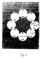
- phase 1 shows a customary 8PSK modulation, in which the individual different phase states ⁇ 1 - ⁇ 8, each keyed with the same amplitude A1 to A8, are arranged on a circle symmetrically to the center of the vector diagram.
- FIG. 2 shows an arrangement of the amplitude and phase states a 1 , ⁇ 1 to a 8 , dans 8 of an 8PSK modulation according to FIG. 1 which is optimized with respect to transmitter power.
- the individual decision circles r of the individual amplitude and phase states are no longer 1, but nested in the vector diagram V such that only four amplitude and phase states lie on an outer circle R1, while four of the amplitude and phase states are shifted inward towards the center of the vector diagram, that they are on a smaller circle R2.
- Fig. 2 also shows that the size of the decision circles compared to Fig. 1 are the same and these decision circles touch each other again.
- 8POM Power Optimized Modulation
- the power reduction can also be used as a modulation gain be considered and other benefits such as larger coverage area, lower bit error rate or Express the smaller dimension of the receiving antenna.
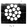
- FIG. 3 shows a conventional 16QAM modulation method with 16 amplitude and phase states a 1 , ⁇ 1 to a 16 , ⁇ 16 arranged side by side in rows and rows, to which decision circles r 1 of the same size are assigned.
- these amplitude and phase states with associated decision circles of equal size can be distributed within the comprehensive circle U with radius R 3 such that the decision circles adopted from FIG. 3 no longer touch.
- This means that the actual, touching decision-making circles are larger, so the modulation process is optimized with regard to clear status detection (16 COM Circle Optimized Modulation).
- the area of each individual decision circle for the respective amplitude and phase states can be increased in this way by approx. 35% while maintaining the peak modulation (peak power) specified according to FIG. 3.
- FIG. 5 shows another possibility for optimizing the original 16 QAM method according to FIG. 3, namely that the performance is optimized again while maintaining the size of the decision circles.
- the arrangement of the decision circles shown in FIG 0.47 dB (10%) can be reduced.
- This known modulation optimization according to FIG. 1 to 4 is according to the invention for each individual carrier a known multi-carrier transmission method used where a multitude of individual ones lying side by side Carriers is provided. So every carrier becomes after this known per se for mono-carrier transmission methods Modulation process modulated. Above all, they are suitable for this the digital technologies that are now available with microcontrollers and digital signal processors, such as those are described in SHARP "An Ultra-High Speed DSP Chip Set For Real-Time Applications ", M.E. Fleming, Sharp Electronics GmbH, Hamburg.
- Fig. 5 shows the Principle structure of such a digitally working modulator using a IFFT (Inverse Fast Fourier Transformation).
- IFFT Inverse Fast Fourier Transformation
- the serial data stream to be modulated onto the carriers of the multi-carrier package is processed in a processor 10 in such a way that the complex amplitude and phase states (for example a1, ⁇ 1 ) stored here, depending on the importance of the modulation (e.g. 8POM according to FIG. 2) to a 8 , ⁇ 8 ) addressed by real part and imaginary part and then fed to a FET processor 11 for the IFFT.
- the IFFT is then carried out in this processor 11 along the stride length, ie the time in which the modulation points of all carriers of the multi-carrier package are constant, and supplies the samples in the time plane in equidistant steps according to the laws of the Fourier transformation.
- the digital I and Q values generated in this way are then converted into corresponding analog signals I A and Q A via digital / analog converters and then a conventional IQ modulator, constructed from two double-sideband modulators 12 and 13, each at 90 ° to one another phase-shifted carriers converted into the modulation signal, which is then fed directly to the transmitter.
- Fig. 6 shows the associated demodulator in the receiver.
- the received high-frequency signal is converted into the signals I A and Q A in an IQ demodulator by means of a reference-controlled generator.
- the frequency and phase reference for the reference-controlled generator is contained in the modulation signal in a time-discrete manner (reference symbol) or is obtained from the modulation signal by averaging.
- the signals I A and Q A are fed back to an FFT processor after A / D conversion, the FFT algorithm results in the complex amplitude and phase states, i.e. in the case of a multi-carrier transmission method the complex states of each individual carrier with an equidistant frequency. From these recovered amplitude and phase states, the original digital data stream is recovered by a subsequent processor, which is then further processed in the receiver.
Landscapes
- Engineering & Computer Science (AREA)
- Computer Networks & Wireless Communication (AREA)
- Signal Processing (AREA)
- Digital Transmission Methods That Use Modulated Carrier Waves (AREA)
- Instructional Devices (AREA)
- Radio Transmission System (AREA)
Description
Claims (1)
- Verfahren zum Übertragen von digitalen Daten über eine Vielzahl von nebeneinanderliegenden getrennten Hochfrequenzträgern (Multiträger-Übertragungsverfahren), bei dem jeder einzelne Träger mit den zu übertragenden Daten nach einem höherwertigen Modulationsverfahren mit kombinierter Umtastung zwischen Amplituden- und/oder Phasenzuständen moduliert ist, derart, daß die den einzelnen Amplituden- und Phasenzuständen im Vektordiagramm zugeordneten Entscheidungskreise für eindeutige Zustandserkennung sich nicht überlappen, dadurch gekennzeichnet, daß für jeden einzelnen Träger die Lage der Amplituden- und Phasenzustände im Vektordiagramm nach ausgewählten Optimierungskriterien der Modulation frei gewählt ist.
Applications Claiming Priority (2)
| Application Number | Priority Date | Filing Date | Title |
|---|---|---|---|
| DE4318547A DE4318547A1 (de) | 1993-06-04 | 1993-06-04 | Verfahren zur digitalen Modulation mit Sinusträger |
| DE4318547 | 1993-06-04 |
Publications (3)
| Publication Number | Publication Date |
|---|---|
| EP0629069A2 EP0629069A2 (de) | 1994-12-14 |
| EP0629069A3 EP0629069A3 (en) | 1995-01-04 |
| EP0629069B1 true EP0629069B1 (de) | 1998-09-30 |
Family
ID=6489608
Family Applications (1)
| Application Number | Title | Priority Date | Filing Date |
|---|---|---|---|
| EP94106869A Expired - Lifetime EP0629069B1 (de) | 1993-06-04 | 1994-05-03 | Multiträger-Übertragungsverfahren |
Country Status (4)
| Country | Link |
|---|---|
| EP (1) | EP0629069B1 (de) |
| JP (1) | JPH0799525A (de) |
| AT (1) | ATE171829T1 (de) |
| DE (2) | DE4318547A1 (de) |
Families Citing this family (3)
| Publication number | Priority date | Publication date | Assignee | Title |
|---|---|---|---|---|
| DE19535075A1 (de) * | 1994-10-21 | 1996-04-25 | Deutsche Telekom Ag | Digitalmodulation |
| DE19535030A1 (de) * | 1994-10-21 | 1996-04-25 | Deutsche Telekom Ag | Verfahren zur Übertragung von Signalen |
| DE102009030675B4 (de) | 2009-06-26 | 2019-05-16 | Rohde & Schwarz Gmbh & Co. Kg | Verfahren und Vorrichtung zum Senden und Empfangen von Signalen mit Modulationskompression |
Family Cites Families (3)
| Publication number | Priority date | Publication date | Assignee | Title |
|---|---|---|---|---|
| JPS5125303B1 (de) * | 1971-02-10 | 1976-07-30 | ||
| US4660213A (en) * | 1983-11-22 | 1987-04-21 | Infinet, Inc. | Signal structure for data communication |
| EP0373277B1 (de) * | 1988-12-13 | 1993-08-25 | International Business Machines Corporation | Mehrfrequenzmodem unter Verwendung trellis-kodierter Modulation |
-
1993
- 1993-06-04 DE DE4318547A patent/DE4318547A1/de not_active Withdrawn
-
1994
- 1994-05-03 AT AT94106869T patent/ATE171829T1/de not_active IP Right Cessation
- 1994-05-03 DE DE59406994T patent/DE59406994D1/de not_active Expired - Fee Related
- 1994-05-03 EP EP94106869A patent/EP0629069B1/de not_active Expired - Lifetime
- 1994-06-03 JP JP6156364A patent/JPH0799525A/ja active Pending
Also Published As
| Publication number | Publication date |
|---|---|
| DE4318547A1 (de) | 1994-12-08 |
| DE59406994D1 (de) | 1998-11-05 |
| EP0629069A3 (en) | 1995-01-04 |
| EP0629069A2 (de) | 1994-12-14 |
| ATE171829T1 (de) | 1998-10-15 |
| JPH0799525A (ja) | 1995-04-11 |
Similar Documents
| Publication | Publication Date | Title |
|---|---|---|
| EP0065764B1 (de) | Digitales Funksystem | |
| DE60023513T2 (de) | Verfahren und gerät zum verringern des verhältnisses zwischen spitzen und mittlerer leistung in digitalen rundfunksystemen | |
| DE60032603T2 (de) | Verfahren und vorrichtung zur bestimung des übertragungssmodus und der synchronisation für ein digitales tonrundfunksignal | |
| DE69322785T2 (de) | Ubertragungssystem fur digitalsignale mit frequenzmultiplex | |
| DE69735724T2 (de) | Zellulares System mit optischer Verbindung zwischen Mobilfernsprechvermittlung und Zellenstandorten | |
| DE60129884T2 (de) | Einrichtung zur Mehrträgermodulation sowie -Multiplexierung | |
| DE69521033T2 (de) | Verfahren und vorrichtung für am verträglichen digitalrundfunk | |
| DE69635689T2 (de) | CDMA-Basisstationssender | |
| DE69330964T2 (de) | Verfahren und anordnung zur dynamischen zuteilung mehrerer trägerwellenkanäle für mehrfachzugriff durch frequenzmultiplex | |
| DE19581527C2 (de) | Digitale Mehrkanalempfänger, Verfahren, digitale Mehrkanalsender, Sender, Aufwärtswandler/Modulator sowie Mehrfachbetriebsart-Aufwärtswandler/Modulator | |
| DE19857821A1 (de) | Verfahren und Kommunikationsanordnung zur Übermittlung von Informationen mit Hilfe eines Multiträgerverfahrens | |
| DE19752200C1 (de) | Übertragungssystem zum Steuern der Sendeleistung in Funkzellen eines Funk-Teilnehmeranschlußnetzes | |
| EP0848877B1 (de) | Verfahren zum übertragen von digitalen daten über störbehaftete rundfunkkanäle und vorrichtung zum empfang von über störbehaftete rundfunkkanäle übermittelten digitale daten | |
| DE69934872T2 (de) | Reduktion des crest-faktors in einem ofdm-signal | |
| DE4445823B4 (de) | Sendevorrichtung für mobile Satellitenkommunikations-Datenstation | |
| EP0974210A1 (de) | System zur übertragung hochratiger mehrwertdienste im terrestrischen digitalen rundfunk | |
| EP0629069B1 (de) | Multiträger-Übertragungsverfahren | |
| DE102009030675B4 (de) | Verfahren und Vorrichtung zum Senden und Empfangen von Signalen mit Modulationskompression | |
| DE2901670B1 (de) | Nachrichtenuebertragungssystem fuer elektromagnetische Wellen | |
| EP0064131B1 (de) | Digitales Modulationsverfahren | |
| EP0696112B1 (de) | Ortsfeste oder mobile Funkstation für ein SDMA-Mobilfunksystem | |
| EP0612460B1 (de) | Funkübertragungsverfahren mittels einer ortsfesten basisstation und einer vielzahl voneinander unabhängiger ortsfester teilnehmerstationen | |
| DE102021106088A1 (de) | Kabellose Empfängerspulenvorrichtung für Magnetresonanz, kabelloses Empfangsverfahren für Magnetresonanzsignale und Magnetresonanzsystem | |
| DE19543622C2 (de) | Verfahren und Vorrichtung zum bidirektionalen Übertragen von hochratigen Digitalsignalen | |
| DE19944558C2 (de) | Verfahren zum Senden von Funksignalen und Sender zum Versenden eines Funksignals |
Legal Events
| Date | Code | Title | Description |
|---|---|---|---|
| PUAI | Public reference made under article 153(3) epc to a published international application that has entered the european phase |
Free format text: ORIGINAL CODE: 0009012 |
|
| PUAL | Search report despatched |
Free format text: ORIGINAL CODE: 0009013 |
|
| AK | Designated contracting states |
Kind code of ref document: A2 Designated state(s): AT BE CH DE DK ES FR GB GR IE IT LI NL PT SE |
|
| AK | Designated contracting states |
Kind code of ref document: A3 Designated state(s): AT BE CH DE DK ES FR GB GR IE IT LI NL PT SE |
|
| 17P | Request for examination filed |
Effective date: 19950127 |
|
| GRAG | Despatch of communication of intention to grant |
Free format text: ORIGINAL CODE: EPIDOS AGRA |
|
| GRAG | Despatch of communication of intention to grant |
Free format text: ORIGINAL CODE: EPIDOS AGRA |
|
| GRAH | Despatch of communication of intention to grant a patent |
Free format text: ORIGINAL CODE: EPIDOS IGRA |
|
| 17Q | First examination report despatched |
Effective date: 19980310 |
|
| GRAH | Despatch of communication of intention to grant a patent |
Free format text: ORIGINAL CODE: EPIDOS IGRA |
|
| GRAA | (expected) grant |
Free format text: ORIGINAL CODE: 0009210 |
|
| AK | Designated contracting states |
Kind code of ref document: B1 Designated state(s): AT BE CH DE DK ES FR GB GR IE IT LI NL PT SE |
|
| PG25 | Lapsed in a contracting state [announced via postgrant information from national office to epo] |
Ref country code: NL Free format text: LAPSE BECAUSE OF FAILURE TO SUBMIT A TRANSLATION OF THE DESCRIPTION OR TO PAY THE FEE WITHIN THE PRESCRIBED TIME-LIMIT Effective date: 19980930 Ref country code: IT Free format text: LAPSE BECAUSE OF FAILURE TO SUBMIT A TRANSLATION OF THE DESCRIPTION OR TO PAY THE FEE WITHIN THE PRESCRIBED TIME-LIMIT;WARNING: LAPSES OF ITALIAN PATENTS WITH EFFECTIVE DATE BEFORE 2007 MAY HAVE OCCURRED AT ANY TIME BEFORE 2007. THE CORRECT EFFECTIVE DATE MAY BE DIFFERENT FROM THE ONE RECORDED. Effective date: 19980930 Ref country code: GR Free format text: LAPSE BECAUSE OF NON-PAYMENT OF DUE FEES Effective date: 19980930 Ref country code: ES Free format text: THE PATENT HAS BEEN ANNULLED BY A DECISION OF A NATIONAL AUTHORITY Effective date: 19980930 |
|
| REF | Corresponds to: |
Ref document number: 171829 Country of ref document: AT Date of ref document: 19981015 Kind code of ref document: T |
|
| REG | Reference to a national code |
Ref country code: CH Ref legal event code: EP |
|
| GBT | Gb: translation of ep patent filed (gb section 77(6)(a)/1977) |
Effective date: 19981001 |
|
| REF | Corresponds to: |
Ref document number: 59406994 Country of ref document: DE Date of ref document: 19981105 |
|
| ET | Fr: translation filed | ||
| REG | Reference to a national code |
Ref country code: IE Ref legal event code: FG4D Free format text: GERMAN |
|
| PG25 | Lapsed in a contracting state [announced via postgrant information from national office to epo] |
Ref country code: PT Free format text: LAPSE BECAUSE OF FAILURE TO SUBMIT A TRANSLATION OF THE DESCRIPTION OR TO PAY THE FEE WITHIN THE PRESCRIBED TIME-LIMIT Effective date: 19981230 |
|
| PG25 | Lapsed in a contracting state [announced via postgrant information from national office to epo] |
Ref country code: SE Free format text: LAPSE BECAUSE OF FAILURE TO SUBMIT A TRANSLATION OF THE DESCRIPTION OR TO PAY THE FEE WITHIN THE PRESCRIBED TIME-LIMIT Effective date: 19981231 Ref country code: DK Free format text: LAPSE BECAUSE OF FAILURE TO SUBMIT A TRANSLATION OF THE DESCRIPTION OR TO PAY THE FEE WITHIN THE PRESCRIBED TIME-LIMIT Effective date: 19981231 |
|
| NLV1 | Nl: lapsed or annulled due to failure to fulfill the requirements of art. 29p and 29m of the patents act | ||
| PG25 | Lapsed in a contracting state [announced via postgrant information from national office to epo] |
Ref country code: AT Free format text: LAPSE BECAUSE OF NON-PAYMENT OF DUE FEES Effective date: 19990503 |
|
| PG25 | Lapsed in a contracting state [announced via postgrant information from national office to epo] |
Ref country code: IE Free format text: LAPSE BECAUSE OF NON-PAYMENT OF DUE FEES Effective date: 19990504 |
|
| PG25 | Lapsed in a contracting state [announced via postgrant information from national office to epo] |
Ref country code: LI Free format text: LAPSE BECAUSE OF NON-PAYMENT OF DUE FEES Effective date: 19990531 Ref country code: CH Free format text: LAPSE BECAUSE OF NON-PAYMENT OF DUE FEES Effective date: 19990531 Ref country code: BE Free format text: LAPSE BECAUSE OF NON-PAYMENT OF DUE FEES Effective date: 19990531 |
|
| REG | Reference to a national code |
Ref country code: IE Ref legal event code: FD4D |
|
| PLBE | No opposition filed within time limit |
Free format text: ORIGINAL CODE: 0009261 |
|
| STAA | Information on the status of an ep patent application or granted ep patent |
Free format text: STATUS: NO OPPOSITION FILED WITHIN TIME LIMIT |
|
| 26N | No opposition filed | ||
| BERE | Be: lapsed |
Owner name: ROHDE & SCHWARZ G.M.B.H. & CO. K.G. Effective date: 19990531 |
|
| REG | Reference to a national code |
Ref country code: CH Ref legal event code: PL |
|
| PGFP | Annual fee paid to national office [announced via postgrant information from national office to epo] |
Ref country code: GB Payment date: 20010417 Year of fee payment: 8 |
|
| PGFP | Annual fee paid to national office [announced via postgrant information from national office to epo] |
Ref country code: FR Payment date: 20010518 Year of fee payment: 8 |
|
| PGFP | Annual fee paid to national office [announced via postgrant information from national office to epo] |
Ref country code: DE Payment date: 20010730 Year of fee payment: 8 |
|
| REG | Reference to a national code |
Ref country code: GB Ref legal event code: IF02 |
|
| PG25 | Lapsed in a contracting state [announced via postgrant information from national office to epo] |
Ref country code: GB Free format text: LAPSE BECAUSE OF NON-PAYMENT OF DUE FEES Effective date: 20020503 |
|
| PG25 | Lapsed in a contracting state [announced via postgrant information from national office to epo] |
Ref country code: DE Free format text: LAPSE BECAUSE OF NON-PAYMENT OF DUE FEES Effective date: 20021203 |
|
| GBPC | Gb: european patent ceased through non-payment of renewal fee |
Effective date: 20020503 |
|
| PG25 | Lapsed in a contracting state [announced via postgrant information from national office to epo] |
Ref country code: FR Free format text: LAPSE BECAUSE OF NON-PAYMENT OF DUE FEES Effective date: 20030131 |
|
| REG | Reference to a national code |
Ref country code: FR Ref legal event code: ST |