EP0629098A2 - Haushaltszähler - Google Patents
Haushaltszähler Download PDFInfo
- Publication number
- EP0629098A2 EP0629098A2 EP94107629A EP94107629A EP0629098A2 EP 0629098 A2 EP0629098 A2 EP 0629098A2 EP 94107629 A EP94107629 A EP 94107629A EP 94107629 A EP94107629 A EP 94107629A EP 0629098 A2 EP0629098 A2 EP 0629098A2
- Authority
- EP
- European Patent Office
- Prior art keywords
- meter
- meters
- hub
- hubs
- chain
- Prior art date
- Legal status (The legal status is an assumption and is not a legal conclusion. Google has not performed a legal analysis and makes no representation as to the accuracy of the status listed.)
- Granted
Links
Images


Classifications
-
- H—ELECTRICITY
- H04—ELECTRIC COMMUNICATION TECHNIQUE
- H04Q—SELECTING
- H04Q9/00—Arrangements in telecontrol or telemetry systems for selectively calling a substation from a main station, in which substation desired apparatus is selected for applying a control signal thereto or for obtaining measured values therefrom
-
- G—PHYSICS
- G08—SIGNALLING
- G08C—TRANSMISSION SYSTEMS FOR MEASURED VALUES, CONTROL OR SIMILAR SIGNALS
- G08C17/00—Arrangements for transmitting signals characterised by the use of a wireless electrical link
- G08C17/02—Arrangements for transmitting signals characterised by the use of a wireless electrical link using a radio link
-
- H—ELECTRICITY
- H02—GENERATION; CONVERSION OR DISTRIBUTION OF ELECTRIC POWER
- H02J—ELECTRIC POWER NETWORKS; CIRCUIT ARRANGEMENTS OR SYSTEMS FOR SUPPLYING OR DISTRIBUTING ELECTRIC POWER; SYSTEMS FOR STORING ELECTRIC ENERGY
- H02J13/00—Circuit arrangements for providing remote monitoring or remote control of equipment in a power distribution network
- H02J13/12—Monitoring network conditions, e.g. electrical magnitudes or operational status
-
- H—ELECTRICITY
- H02—GENERATION; CONVERSION OR DISTRIBUTION OF ELECTRIC POWER
- H02J—ELECTRIC POWER NETWORKS; CIRCUIT ARRANGEMENTS OR SYSTEMS FOR SUPPLYING OR DISTRIBUTING ELECTRIC POWER; SYSTEMS FOR STORING ELECTRIC ENERGY
- H02J13/00—Circuit arrangements for providing remote monitoring or remote control of equipment in a power distribution network
- H02J13/13—Circuit arrangements for providing remote monitoring or remote control of equipment in a power distribution network characterised by the transmission of data to equipment in the power network
- H02J13/1331—Circuit arrangements for providing remote monitoring or remote control of equipment in a power distribution network characterised by the transmission of data to equipment in the power network using wireless data transmission
-
- H—ELECTRICITY
- H02—GENERATION; CONVERSION OR DISTRIBUTION OF ELECTRIC POWER
- H02J—ELECTRIC POWER NETWORKS; CIRCUIT ARRANGEMENTS OR SYSTEMS FOR SUPPLYING OR DISTRIBUTING ELECTRIC POWER; SYSTEMS FOR STORING ELECTRIC ENERGY
- H02J13/00—Circuit arrangements for providing remote monitoring or remote control of equipment in a power distribution network
- H02J13/13—Circuit arrangements for providing remote monitoring or remote control of equipment in a power distribution network characterised by the transmission of data to equipment in the power network
- H02J13/1337—Circuit arrangements for providing remote monitoring or remote control of equipment in a power distribution network characterised by the transmission of data to equipment in the power network involving the use of Internet protocols
-
- H—ELECTRICITY
- H04—ELECTRIC COMMUNICATION TECHNIQUE
- H04Q—SELECTING
- H04Q2209/00—Arrangements in telecontrol or telemetry systems
- H04Q2209/20—Arrangements in telecontrol or telemetry systems using a distributed architecture
- H04Q2209/25—Arrangements in telecontrol or telemetry systems using a distributed architecture using a mesh network, e.g. a public urban network such as public lighting, bus stops or traffic lights
-
- H—ELECTRICITY
- H04—ELECTRIC COMMUNICATION TECHNIQUE
- H04Q—SELECTING
- H04Q2209/00—Arrangements in telecontrol or telemetry systems
- H04Q2209/40—Arrangements in telecontrol or telemetry systems using a wireless architecture
-
- H—ELECTRICITY
- H04—ELECTRIC COMMUNICATION TECHNIQUE
- H04Q—SELECTING
- H04Q2209/00—Arrangements in telecontrol or telemetry systems
- H04Q2209/60—Arrangements in telecontrol or telemetry systems for transmitting utility meters data, i.e. transmission of data from the reader of the utility meter
-
- Y—GENERAL TAGGING OF NEW TECHNOLOGICAL DEVELOPMENTS; GENERAL TAGGING OF CROSS-SECTIONAL TECHNOLOGIES SPANNING OVER SEVERAL SECTIONS OF THE IPC; TECHNICAL SUBJECTS COVERED BY FORMER USPC CROSS-REFERENCE ART COLLECTIONS [XRACs] AND DIGESTS
- Y02—TECHNOLOGIES OR APPLICATIONS FOR MITIGATION OR ADAPTATION AGAINST CLIMATE CHANGE
- Y02E—REDUCTION OF GREENHOUSE GAS [GHG] EMISSIONS, RELATED TO ENERGY GENERATION, TRANSMISSION OR DISTRIBUTION
- Y02E60/00—Enabling technologies; Technologies with a potential or indirect contribution to GHG emissions mitigation
-
- Y—GENERAL TAGGING OF NEW TECHNOLOGICAL DEVELOPMENTS; GENERAL TAGGING OF CROSS-SECTIONAL TECHNOLOGIES SPANNING OVER SEVERAL SECTIONS OF THE IPC; TECHNICAL SUBJECTS COVERED BY FORMER USPC CROSS-REFERENCE ART COLLECTIONS [XRACs] AND DIGESTS
- Y04—INFORMATION OR COMMUNICATION TECHNOLOGIES HAVING AN IMPACT ON OTHER TECHNOLOGY AREAS
- Y04S—SYSTEMS INTEGRATING TECHNOLOGIES RELATED TO POWER NETWORK OPERATION, COMMUNICATION OR INFORMATION TECHNOLOGIES FOR IMPROVING THE ELECTRICAL POWER GENERATION, TRANSMISSION, DISTRIBUTION, MANAGEMENT OR USAGE, i.e. SMART GRIDS
- Y04S10/00—Systems supporting electrical power generation, transmission or distribution
- Y04S10/30—State monitoring, e.g. fault, temperature monitoring, insulator monitoring, corona discharge
-
- Y—GENERAL TAGGING OF NEW TECHNOLOGICAL DEVELOPMENTS; GENERAL TAGGING OF CROSS-SECTIONAL TECHNOLOGIES SPANNING OVER SEVERAL SECTIONS OF THE IPC; TECHNICAL SUBJECTS COVERED BY FORMER USPC CROSS-REFERENCE ART COLLECTIONS [XRACs] AND DIGESTS
- Y04—INFORMATION OR COMMUNICATION TECHNOLOGIES HAVING AN IMPACT ON OTHER TECHNOLOGY AREAS
- Y04S—SYSTEMS INTEGRATING TECHNOLOGIES RELATED TO POWER NETWORK OPERATION, COMMUNICATION OR INFORMATION TECHNOLOGIES FOR IMPROVING THE ELECTRICAL POWER GENERATION, TRANSMISSION, DISTRIBUTION, MANAGEMENT OR USAGE, i.e. SMART GRIDS
- Y04S40/00—Systems for electrical power generation, transmission, distribution or end-user application management characterised by the use of communication or information technologies, or communication or information technology specific aspects supporting them
- Y04S40/12—Systems for electrical power generation, transmission, distribution or end-user application management characterised by the use of communication or information technologies, or communication or information technology specific aspects supporting them characterised by data transport means between the monitoring, controlling or managing units and monitored, controlled or operated electrical equipment
- Y04S40/126—Systems for electrical power generation, transmission, distribution or end-user application management characterised by the use of communication or information technologies, or communication or information technology specific aspects supporting them characterised by data transport means between the monitoring, controlling or managing units and monitored, controlled or operated electrical equipment using wireless data transmission
Definitions
- the present invention relates to a communication system comprising a chain of meters, and a meter for use in such a system.
- Reading of utility meters provided in domestic and industrial premises has traditionally been undertaken manually. In the electricity and gas industry, readings are taken once per quarter, though in an effort to reduce the manpower required, there is currently a move towards customer-read, or estimated readings, with readings by the utility taking place only once per year.
- Automated meter reading would reduce the manpower cost, but could involve a large capital outlay, both in the provision of new meters, and in the communication links required. Particularly in the case of domestic metering, the outlay could be large relative to the amounts billed from each customer.
- radio communications In considering the communication costs, to avoid expensive cabling schemes, it is known to use radio communications.
- radio communications there are a number of disadvantages with radio communications, including the limited range which is possible using the available bands, the cost of the large number of repeater stations that would be required, and the lack of reliability of communication at extreme range due to interference from other radios, due to the weather, and due to the local topography.
- the present invention seeks to provide a remedy.
- a communication system comprising a chain of meters, each meter communicating with others in the chain to pass information along the chain, for remote reading of a utility such as gas, liquid or electricity, supplied, produced or used at a given location, and comprising: a measurement means for the utility supplied, produced or used, a radio receiver, and a radio transmitter for transmitting measurement information generated by the measurement means, and arranged to operate with the radio receiver to pass along the chain information received by the receiver.
- a utility such as gas, liquid or electricity
- a hub connecting a plurality of chains of meters in a star formation or a loop formation.
- a data gatherer connecting a plurality of hubs in a star formation or a loop formation.
- two or more communication paths are defined along one chain or part of a chain, each path being created by bypassing the meters used by the other path or paths.
- said multiple communication paths are provided in the vicinity of junctions between chains, or in the vicinity of a hub.
- each meter determines part of the route of the communication path, by bypassing neighbouring meters.
- the hub determines part of the route of the communication path.
- the system comprises: a plurality of hubs, each connected to a plurality of meters, wherein upon failure of a hub, neighbouring hubs are reconfigured to communicate with meters normally communicating with the failed hub.
- each hub contains a map of meters normally communicating with it, and a map of meters normally communicating with neighbouring hubs.
- the hubs are in communication with a network management system, which instructs the neighbouring hubs to reconfigure, in response to an indication that the failed hub has failed.
- the invention provides a meter for use in the above communication system.
- the meter is arranged to receive and store measurement information from a neighbouring meter and pass this information on when failure of the neighbouring meter is detected.
- meter comprises: means for storing and updating a tariff of charges, and processing means for calculating a total charge from a plurality of readings charged at different rates.
- the meter is for remote reading of gas or liquid utilities in domestic premises, and comprises: means for monitoring the gas or liquid pressure, means for storing a reference pressure level, and means for indicating when the monitored pressure is over or under the reference level.
- the meters are for use in domestic premises, and form part of a utility supply system, wherein each meter comprises: means for monitoring a parameter of quality of the utility supplied, and the supply system comprises means for controlling the supply of the utility from a central source to the domestic premises in response to quality information transmitted by the meter.
- the meter is for liquid or gas metering, and comprises: pressure control means for allowing the gas or liquid to be supplied at a reduced pressure, according to commands received by the receiver.
- Figure 1 shows the application of this invention to automated reading of domestic water supply meters. Communication is required from each premises, or house, 1 in which the water is consumed, to a data gatherer station 2 where meter reading information is collected for storage in a network management system (DomMan).
- the management system has overall control of the network and the configuration of the network.
- the data gatherer 2 temporarily stores meter reading information before it is read out by the management system 7. From there it can be sent to a billing computer 8.
- the figure illustrates the connection to the billing system computer, via a LAN, e.g. an ethernet link, and to a network management system (DomMan).
- Outstations 3 may conveniently be sited at sewage pumping stations, since these are already owned by the utilities, and have suitable power supply facilities. In some cases these sites already have communication links with the data gatherer station 2.
- a plurality of outstations are provided, each connected to the data gatherer by scanning radio, or by PSTN (public switched telephone network) or a combination of these or other methods.
- the data gatherer 2 manages the communications between the network manager and these hubs. These hubs may store a map of the meters they serve. Low power radio using the 458 MHz band may be used to link the hubs to the outstations. Alternatively, where appropriate, a hub may be located at an outstation and physically wired to it. Communication could be made directly between hubs and the data gatherer by radio or PSTN. Lower power 184 MHz radio may be used between meters and hubs, and to communicate between meters. Other bands may be used depending on allocation by the regulatory authorities.
- each meter passes on messages and data from other meters.
- a hub can be connected directly to one or more chains of meters and thus hundreds of meters can be connected to a hub, and many hubs connected to each outstation, with a minimum of capital expenditure on dedicated infrastructure.
- hubs would be determined by (a) a desire to have the minimum necessary quantity of hubs, and (b) the desire to optimise the communications efficiency to meters at the furthest extremities of the cell, thereby minimising the use of battery power within any of the meters within the cell.
- determination of location of the hubs would be a process that would comprise modelling of communications within the meter network prior to siting and installation of the hubs.
- the network management system would ensure that the network is optimised to minimise excessive use of meters' batteries through inefficient communications routes.
- the network management system would thus extract the meter network map from each of the hubs, would create a complete map of the whole area covered by all the cells, and would optimise the coverage of each primary cell to ensure that individual meters were not subject to excessive communications loading.
- the optimised primary cell size for each of the hubs would then be sent by the network management system to the individual hubs (probably in the form of a list of meters).
- the length of chains of meters will be limited by the amount of data which needs to be transmitted by the meters closest to the hub. Also, the chain may reach an impasse if the gap between properties is greater than a given distance, typically, approximately 50 metres, depending on the circumstances. If necessary, the aerial can be sited above ground to achieve a greater range. Nevertheless, where the spacing between houses is small e.g. less than 50 metres, then leap-frogging along the chain is possible, with every second or third meter being used for a particular transmission. If arranged so that re-transmission by a number of different routes is possible, then there is considerable built in resilience in the case of a single meter failure, for example due to malfunction, or due to a car being parked over the site of the aerial.
- the network is extremely flexible, so that it can accommodate higher data rates where required, or can be rearranged for lower overall data rate, but higher reliability.
- meter chains can communicate with outstations directly, or via the PSTN, or using combinations of these three possibilities.
- Hubs are preferred, in order to enable shorter chains, or to reduce the number of outstations required. Data may need to be passed via many hubs to reach the nearest outstation. Depending on aerial position and other factors, the spacing of the hubs could be typically 500 metres depending on the circumstances. In practice, in urban areas at least, hubs can conveniently be attached to street lamps, to achieve a good height above the ground, for increased range. This might also enable use of the street lamp power supply. If mounted on a separate post, a battery could be used as the power supply. In this case, the network, and communication protocols should be arranged to minimise power consumption.
- Hubs can be used to overcome breaks in the chains of meters.
- the data rate loading can be considerably reduced on the meters nearest to the hub.
- routes for data can be used, to build in redundancy, and therefore reliability, by connecting chains to more than one hub, or by connecting chains in loops so that both ends communicate with a hub.
- Communication can be in two directions, either into the data gatherer from each meter, for meter reading, and monitoring purposes, or in the opposite direction, out to each meter, for control purposes.
- the purposes and advantages of this two-way communication will be explained in more detail later, when an individual meter will be described.
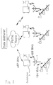
- FIG. 2 shows an arrangement in which sewage pumping stations are used as the locations for the outstations 3 in the system. Further options are shown in Figure 4.
- Meter chains can communicate with an outstation via the public service telephone network (PSTN). Either a dedicated telephone link could be used, with a radio transmitter and receiver within approximately 50 metres of one of the meters, or the domestic telephone line belonging to one of the water consumers could be used. Alternatively, a dedicated mobile telephone could be used.
- PSTN public service telephone network
- Figure 4 also shows chains of meters communicating directly with the outstation 3.
- the third possibility, of chains communicating with the outstation 3 via a hub 5 is also shown.
- Figure 5 shows a plan view of streets in a typical housing area, with the location of domestic meters along the sides of the streets indicated by small circles.
- the area is divided into three cells, each cell having a hub.
- a single outstation 3 services all three hubs.
- FIG. 6 A typical cell structure is shown in Figure 6, the spacing between each hub being in practice approximately 500 metres, depending on the circumstances. In the event of failure of a cell, neighbouring cells can be reconfigured to collect meter readings from the meters in the failed cell. Figure 7 shows such a situation, when cell G has failed. To enable this, each hub or outstation must be sufficiently intelligent to carry and use a map of meters in its own cell, and meters in adjacent cells.
- the data gatherer would also identify for each cell, additional secondary areas within each of the neighbouring cells.
- additional secondary areas For a hexagonal cell structure (for example), a single hub would have a primary cell coverage, plus 6 additional secondary areas, with each additional secondary area representing 1/6th of the area of each neighbouring cell.
- the hubs in the neighbouring 6 cells could thus be instructed to expand their cell area to include the appropriate secondary area.
- each meter can communicate not only with its nearest neighbour, but also with other slightly more distant meters.
- Figure 8 shows a number of meters located on either side of a road, and shows communication paths from one meter to ten neighbouring meters. Each meter may have a range of perhaps 50 metres, either above ground, or through the earth or using a combination of these transmission paths. If there are a number of different paths along the chain, then faulty meters may be bypassed, and the maximum data transfer rates for meters closest to hubs can be reduced. This in turn enables longer chains to be constructed, or enables battery life in each meter to be maximised.
- each meter may be the most expensive single component in each meter, so it may be of paramount importance to reduce the amount of data transmitted by the busiest meters, those closest to each hub. To facilitate this, each meter should be sufficiently intelligent to carry and use a map of the neighbouring meters within its radio range.
- FIG. 9 A typical meter reading operation is shown in Figures 9 and 10.
- a message is sent out along a chain by a hub as shown in Figure 9. On this outward journey, the number of hops is minimised.
- Figure 10 shows a typical return journey for the message, collecting meter readings from every meter in the chains.
- Figure 11 shows a more realistic topography, in which chains are connected in a more complex matrix fashion. This enables multiple routes to be chosen from any meter to the hub. Meters near junctions could have enough intelligence to decide how to route data in an optimum way, or the intelligent hub could decide the route, and code it in the message, to be read and interpreted by each meter.
- FIG. 13 shows a diagrammatic representation of a typical meter.
- Measurement means include a measurement sensor 30, and a radio receiver 31 and radio transmitter 32 are also provided.
- the radio transmitter can output measurements from the sensor, optionally via a processor 33. Also, it can operate with the radio receiver 31 as a repeater, or as a store and forward device to transmit information from other meters.
- Each meter could record daily or hourly flows, say storing the last years values in a memory 38 for interrogation in the event of customer queries.
- a first meter could also pass its readings to a neighbouring second meter for storage, in case of failure of the first meter.
- a leak detector 34 In the case of water meters, it has been estimated that 30% of unaccounted for water is lost after the boundary stop-cock of the customer. The meter could monitor flow, and record, for example, the minimum flow in a given period. At the minimum, one "night-flow" value could be recorded and brought back to the data gatherer from each meter. A further degree of sophistication might involve reporting weekly or monthly minimum flows. The leak detector could issue an alarm and transmit this back to the data gatherer, if the leakage was too high.
- the measurement sensor 30 could be operable not only to measure the amount of the utility, such as water, supplied or used, but could also measure one or more parameters of quality of the utility, such as water pressure or mains voltage. In the case of water or gas supply, this could involve measuring the pressure using a pressure transducer. In exceptional circumstances, the meter could raise and report an alarm signal to the data gatherer.
- Meters could continuously or intermittently monitor the quality sensors. Resultant quality information might be regularly recorded in the meter or only exceptions might be recorded (for example, instances of low water pressure might be recorded). A hub could thus read from the meter (a) the recorded quality information, and/or (b) the exceptions, and/or (c) the current value of the quality sensor. In addition, a meter might generate an unsolicited alarm message to be sent to the hub when one of the quality sensors exceeded an alarm condition (for example, if the water pressure was particularly low or if the flow rate was particularly high for a long period of time).
- an alarm condition for example, if the water pressure was particularly low or if the flow rate was particularly high for a long period of time.
- quality information such as pressure or voltage could be fed back via the hub and used as feedback for a controller. For example, if water pressure quality information was returned to a controller and the controller noted that all properties had high pressure, the controller might reduce the water pressure thus reducing the amount of water lost in a zone due to leakage and also reducing the number of burst mains that might occur. Alternatively, if the water pressure was found to be low at a number of houses, the controller might choose to increase the pressure of the water supplied to a zone. Such quality information would also be of benefit to a utility in modelling the operation of the distribution network and the production of management reports detailing the performance of the utility.
- the meter can also make use of information transmitted from the data gatherer.
- a flow controller 35 can be provided to reduce water pressure, when prolonged high flows are detected (possibly due to leakage, or due to unauthorised hose pipe usage). Also, pressure could be reduced during the night to reduce leakage, or during a drought, or on a selective basis where a customer has not paid his bill.
- a further use of communication from the data gatherer out to customer's meters is to enable tariff schemes to be implemented in the meters. This would enable a customer to see the effect of tariff schemes on their individual bills, and would require considerably less data to be returned to the data gatherer.
- Tariffs can for example be hourly, daily, weekly or seasonal. There can be a low night rate tariff, and a high summer tariff. However, in theory, implementation of a tariff scheme would require all the domestic meters to be updated with any new tariffs simultaneously. In practice, several days could be allowed to update all meters.
- Figure 12 shows a tariff storage means 36 connected to the radio receiver, to allow automatic remote updating.
- the processor 33 could include a timing device to indicate when daily or seasonal tariff changes come into effect. The processor would calculate the single total charge over a particular period of time, which would be transmitted back to the data gatherer. This would involve transmitting less data than if raw consumption data for each of the different tariff periods were to be transmitted back to the data gatherer.
- the timing device could be a real time clock (RTC), included within each meter for the purposes of timing of tariffs and possibly for synchronisation of communications between meters. All meters' RTCs will be synchronised to a single master clock in the data gatherer.
- the process of time synchronisation is as follows: the data gatherer would send a message containing the current time to each hub; the hub would set its RTC to the time received from the data gatherer; the hub would send a message containing the current time to the first meter (meter 1) in a chain; on receipt of this message meter 1 would set its RTC to the time received from the hub; meter 1 would send a message containing the current time to the next meter (meter 2) in the chain; on receipt of this message meter 2 would set its RTC to the time received from meter 1; this process would be repeated for all meters in all chains until the network of meters was synchronised.
- RTC real time clock
- Time synchronisation would be undertaken at regular intervals.
- the process of time synchronisation could also be used to check the operation of the meters within the meter network and thus the integrity of the meter network. Any meter or meter network failures could thus either result in a neighbouring meter either (a) sending a message to the hub indicating the failure; or (b) adding a packet to the time synchronisation message so that once the time synchronisation message reached the end of its chain it could be returned to the hub complete with all failure information relating to the chain.
- a tamper alarm, 37 is also shown, connected to the processor 33. This could give an immediate alarm signal back to the data gatherer, and optionally send back a meter reading before the person tampering has had an opportunity to alter the true reading.
- the network management computer In operating the complete system, preferably the network management computer stores a complete meter map indicating which meter is linked to which hub. It also stores routines for coping with hub failure. Whenever the meter map changes, or hub failure is detected, revised meter maps can be downloaded to hubs.
- Each hub contains routing information and communication protocols.
- a polling communication method is preferred for controlling communication between the management computer and each hub.
- the outstations are envisaged as mere communication links, with the intelligence being distributed around the hubs, conceivably intelligent outstations could be provided.
- each hub When directed by the management computer, each hub sends messages out to distribute information or collect meter readings or other information.
- the message normally indicates a destination meter, routes and data where applicable.
- Each meter knows the directions of its neighbours, and determines the best neighbour to attempt communication with, depending on the routes contained in the message.
- a message would contain a number of packets of information. These might include (a) "routing” information, containing information necessary for a message to reach the message's final destination(s); (b) message "type", identifying the purpose of the message; (c) destination meter(s), identifying the meter(s) the message is intended for; (d) "data”, a field either containing information to be sent to the destination meters or a field which is populated by the destination meters with data to be returned to the hub.
- a message might serve more than one function and might thus contain several "type” fields, several sets of destination meters and several data fields. This would enable communications efficiency to be maximised and limit the drain on the meter's battery.
- a message may contain (a) a "broadcast” instruction with data to be sent to selected meters (such as new tariffs); (b) a "read meter” instruction to collect meter readings from selected meters; and (c) a "diagnostic read” instruction to collect any fault conditions as the message is sent through the network and any new meters not already configured.
- a message sent from the hub may contain a complete list of meters that the message must be sent to in order for the message to reach its destination; in this case the message contains all the information needed to reach a given meter, and each meter has no knowledge of the rest of the meter network.
- a second method would be for the hub to send a message containing just the final meter destination of the message: in this case the message contains no network information and each meter in the network has complete knowledge of the network.
- a third method would be for the hub to send a message containing the destination and the route the message is to take to get to the destination: in this case the hub has a complete map of the meter network, the meter has a map of the meters within communicating range and the meter "chains" they are on (a chain being a number of meters in which messages are sent, starting at one end of the chain, from one meter to another until they reach the other end of the chain). In all three cases the hub will need a complete map of the network of meters it is servicing.
- each meter might lie in one or more chains.
- each chain will have two directions.
- the routing information to reach a destination meter might contain a series of chains and directions to take along those chains.
- a meter (meter 1) receiving a message with the routing information would compare the information to its own local map; meter 1's own local map would show at least one chain that was also contained within the message and, this being the case, meter 1 would send the message to another meter further along the chain. If meter 1 identified more than one chain in its own local map that was in the message, then meter 1 would pass the message to a meter on the chain that was closest to the destination meter (this might occur if meter 1 was located at a junction between several chains).
- meter 1 might be able to directly communicate with the destination meter, in which case meter 1 would send the message directly to the destination meter.
- a similar process would occur when a message was being returned to the hub: in this case the final destination meter would alter the message slightly to indicate that the message was to be passed in the reverse direction down the route (unless the route was circular and the final destination was the hub).
- a message that is required to reach all meters would be sent from a meter to its most adjacent neighbouring meter as it is sent down a chain. If, however, the information within a message is just for the meter at the end of a chain, there is no need for the message to be sent via all of the meters in the chain and hence it is envisaged that the messages might be sent via the minimum number of meters, with the maximum distance being achieved on each transmission of the message.
- a third example might be where each meter adds a meter reading to the message as it is passed along a chain: here it can be seen that the meters at the end of the chain will have a significantly longer message to transmit than those at the beginning: to alleviate excessive drain on the meters' batteries it is envisaged that this meter reading collection message might be sent to, say, every third meter in the chain: in such cases three such messages would be sent with the possible option of messages interleaving to optimise traffic in the network.
- meters would configure themselves on installation.
- a meter meter 1
- it might broadcast a message to establish which meters (meters 2) were within communicating range.
- Any meter 2 receiving the broadcast message would respond with a reply containing the meter 2 identification number.
- meter 2 might wait a "random" amount of time before replying.
- Meter 1 can establish a list of all the meters within its range of communications by a combination of (a) meter 1 telling a given meter 2 not to reply to future broadcasts when meter 1 has established communications with that meter 2, and (b) meter 1 repeating the broadcast message; and (c) meter 1 interrogating the meter 2s it establishes communication with to identify the meters with which these meter 2s can communicate with.
- the hub would behave like any other meter 2.
- Alternative methods of meter 1 establishing the local meter list can also be envisaged.
- meter 1 establishes a list of the identity of all the neighbouring meter 2s within communications range, and (b) neighbouring meter 2s add the same information for the meter 1 to their local meter lists.
- the meter communications network would be self-configuring.
- the network management system would provide the hub with a list of meters that it is to service (the meters within the hub's cell). It is envisaged that the hub would build up the network by sending a message to its nearest meters (meter 1s) to read the list of meters (meter 2s) that each of the meter 1s was able to communicate with. The hub would then send a message to the meter 2s via the meter 1s to establish which meters these meter 2s could communicate with. This process would be repeated, for all subsequent meters, with the hub building up a map of how to get to each meter in the cell. In the process of doing this, the hub would thus identify the chains connecting meters, and would send messages to the meters to configure them with the chains they lie on.
- the network is built up by the hub. Changes in the network (for example, communications failures due to meter failures, or changes in signal path conditions affecting the number of meter 2s, the meter 1s can communicate with, or additional unconfigured meters added to the network) would be reported back to the hub via the diagnostic message described above and the hub would then repeat the above process as necessary to adapt the network to the revised meter structure.
- Changes in the network for example, communications failures due to meter failures, or changes in signal path conditions affecting the number of meter 2s, the meter 1s can communicate with, or additional unconfigured meters added to the network
- the measurement sensor of the meter may well be located underground, but the radio receiver and radio transmitter aerials may be either underground or above ground. They may be more visually obtrusive, and more susceptible to damage if above ground, but the range of communication is increased.
- a meter for remote reading of a utility such as gas, liquid or electricity, supplied, produced or used at a given location, comprising: a measurement means for the utility, a radio receiver, and a radio transmitter for transmitting measurement information generated by the measurement means, and arranged to operate with the radio receiver to pass on information received by the receiver.
- the meter further comprises a storage means and a controller, and is arranged to pass on information received by the receiver by a store and forward operation.
- the meter further comprises monitoring means communicating with the radio transmitter for monitoring and reporting a quality of the utility supplied, produced or used, such as water or gas pressure, or electrical supply voltage.
- the meter further comprises leak detection means communicating with the radio transmitter for detecting and reporting fluid leaks or electrical short circuits, particularly those downstream of the meter.
- the meter further comprises flow control means communicating with the radio receiver, to restrict the flow of fluid or current according to radio signals received by the radio receiver.
- the measurement means further comprises means for storing a tariff of charges and processing means for generating measurement information based on the tariff and the measured amounts of the utility used or supplied, wherein the tariff storage means is connected to the radio receiver to enable remote updating of the tariff.
- the radio transmitter and receiver of the meter are arranged to use the 184 MHz band.
- the meter is a domestic water supply meter. As there are currently few water meters installed, the need for upgrade compatibility and redundancy is minimised.
- the meter forms part of a communication system comprising a plurality of the meters arranged in chains around a hub.
- system further comprises at least one outstation, between the hub and the data gatherer.
- system further comprises a telephone data link between a chain of meters and the hub.
- the method of the present invention comprises the step of communicating between the second meter and the data gatherer via a hub.
- the method of the present invention further comprises the step of communicating between the second meter and the hub via a public telephone network.
- the method includes the step of communicating between the hub and the data gatherer via a public telephone network.
- a meter for remote reading of a utility such as gas, liquid or electricity, supplied, produced or used at a given location, comprising: a measurement means for the utility supplied, produced or used; a radio receiver; a radio transmitter; and a controller arranged to control the transmitter for transmitting measurement information generated by the measurement means, and/or information received by the receiver.
- the controller comprises a storage means and is arranged to pass on information by a store and forward operation.
- the present invention has the advantages of minimising the capital cost by reducing the number of secondary repeaters required, and by making use of short range low power radios in each meter.
- the "hopping" concept gives great flexibility in allowable maximum data rates, which can be particularly useful for updating the tariffs in all meters in a short period of time. Reliability of communication can be enhanced by providing multiple paths. Individual meters can be read "out of turn” where required for occupancy changes for example, without any extra cost.
- Various different ways of connecting chains of meters to hubs can be provided to suite local requirements. Mobile hubs provided in vans could even be envisaged, particularly for rural areas. Where necessary, techniques for giving longer transmission range can be adopted such as the spread spectrum technique.
Landscapes
- Engineering & Computer Science (AREA)
- Power Engineering (AREA)
- Computer Networks & Wireless Communication (AREA)
- Physics & Mathematics (AREA)
- General Physics & Mathematics (AREA)
- Arrangements For Transmission Of Measured Signals (AREA)
- Details Of Flowmeters (AREA)
Applications Claiming Priority (2)
| Application Number | Priority Date | Filing Date | Title |
|---|---|---|---|
| GB9310111A GB2278699B (en) | 1993-05-17 | 1993-05-17 | Domestic meter |
| GB9310111 | 1993-05-17 |
Publications (3)
| Publication Number | Publication Date |
|---|---|
| EP0629098A2 true EP0629098A2 (de) | 1994-12-14 |
| EP0629098A3 EP0629098A3 (de) | 1995-01-18 |
| EP0629098B1 EP0629098B1 (de) | 2001-12-12 |
Family
ID=10735599
Family Applications (1)
| Application Number | Title | Priority Date | Filing Date |
|---|---|---|---|
| EP94107629A Expired - Lifetime EP0629098B1 (de) | 1993-05-17 | 1994-05-17 | Haushaltszähler und Versorgungseinrichtung |
Country Status (4)
| Country | Link |
|---|---|
| EP (1) | EP0629098B1 (de) |
| DE (2) | DE629098T1 (de) |
| ES (1) | ES2088837T3 (de) |
| GB (1) | GB2278699B (de) |
Cited By (71)
| Publication number | Priority date | Publication date | Assignee | Title |
|---|---|---|---|---|
| GB2310779A (en) * | 1996-02-27 | 1997-09-03 | Linburg Ltd | Remote meter reading by power line/radio and telephone |
| EP0834849A1 (de) * | 1996-08-31 | 1998-04-08 | Amatsia Dr. Kashti | Messvorrichtung |
| DE19756631A1 (de) * | 1997-12-19 | 1998-07-02 | Detlev Uhle | Verfahren und Vorrichtung zum Betrieb eines automatischen Funknetzes für kommunale und betriebliche Anwendung in der Fernmeß- und Fernsteuerungstechnik mit Funksendern geringer Sendeleistung |
| FR2761842A1 (fr) * | 1997-04-02 | 1998-10-09 | Logiclab | Systeme et procede de transmission de donnees issues d'un ensemble d'automates |
| GB2325589A (en) * | 1997-03-27 | 1998-11-25 | David Hellier | Electric meter transmitting consumption data via cellular radio |
| WO1998055975A1 (en) * | 1997-06-06 | 1998-12-10 | Abb Power T & D Company Inc. | Rf repeater for automatic meter reading system |
| WO1998045717A3 (en) * | 1997-04-10 | 1999-01-07 | Nexsys Commtech International | Remote home monitoring system |
| EP0903709A1 (de) * | 1997-06-18 | 1999-03-24 | Kabushiki Kaisha Toshiba | Fernmesssystem und Kommunikationsgerät dafür |
| EP0907126A1 (de) * | 1997-09-12 | 1999-04-07 | Hewlett-Packard Company | Automatische Konfiguration von Primär- und Sekundärperipheriegeräte für einen Rechner |
| WO1999018553A1 (en) * | 1997-10-03 | 1999-04-15 | Taglioni Communications S.A.S. Di Taglioni Daria & C. | System for measuring domestic consumption of electricity, heat, water and gas |
| WO1999021147A1 (en) * | 1997-10-16 | 1999-04-29 | Cic Global, Llc | System and method for communication between remote locations |
| FR2771235A1 (fr) * | 1997-11-19 | 1999-05-21 | Logiclab | Procede et systeme de gestion de transmissions d'informations entre une pluralite d'automates et un site central de traitement, et systeme de transmission de donnees associe |
| WO1999031633A1 (en) * | 1997-12-16 | 1999-06-24 | Atl Monitors Limited | Remote metering |
| WO1999013676A3 (en) * | 1997-09-12 | 1999-09-02 | Williams Wireless Inc | Wide area telemetry network |
| EP0878892A3 (de) * | 1997-05-15 | 1999-11-17 | ITF-EDV Fröschl GmbH | Verfahren zur Erfassung und/oder Berechnung von abrechnungsrelevanten Verbrauchsgrössen |
| EP0731570A3 (de) * | 1995-02-11 | 1999-12-08 | ABBPATENT GmbH | Zweiwegkommunikationssystem für Energieversorgungsnetze |
| WO2000003221A1 (de) * | 1998-07-09 | 2000-01-20 | Heinrich Weingartner | Durchflussverfahren zur lecküberprüfung von leitungssystemen |
| EP0948113A3 (de) * | 1998-04-04 | 2000-07-05 | PreussenElektra Aktiengesellschaft | Verfahren und Vorrichtung zum Betrieb von Energieverbrauchseinheiten |
| US6145019A (en) * | 1998-03-02 | 2000-11-07 | Hewlett-Packard Company | Unconfigured device that automatically configures itself as the primary device if no other unconfigured device is present |
| WO2000076052A1 (en) * | 1999-06-09 | 2000-12-14 | Motorola Inc. | Utility data transfer system and method |
| WO2001015114A1 (en) * | 1999-08-24 | 2001-03-01 | Digiterm Limited | Interactive system for remote reading of utility meters |
| WO2000057382A3 (en) * | 1999-03-24 | 2001-03-15 | Conectisys Corp | A wireles amr network |
| WO2001024569A1 (de) * | 1999-09-28 | 2001-04-05 | Common-Link Ag | System zum austausch von daten |
| US6349345B1 (en) | 1999-01-29 | 2002-02-19 | Hewlett-Packard Company | Autoconfigurable device that provisionally configures itself as the primary or secondary peripheral device depending on if another peripheral device is present |
| ES2170684A1 (es) * | 2000-07-19 | 2002-08-01 | Automated Meter Reading System | Sistema para la adquisicion y el transporte automatico de lecturas de contadores de agua, gas y electricidad. |
| EP1244083A1 (de) * | 2001-03-21 | 2002-09-25 | Metrix Systems AG | Verfahren zum Erfassen von Verbrauchsdaten |
| WO2002025987A3 (en) * | 2000-09-21 | 2002-12-27 | James Robert Orlosky | Automated meter reading, billing, and payment processing system |
| FR2826485A1 (fr) * | 2001-06-22 | 2002-12-27 | Tekelec Temex | Procede et systeme pour augmenter l'autonomie d'un dispositif emetteur-recepteur radio, et dispositif emetteur-recepteur radio de grande autonomie |
| WO2003088704A3 (en) * | 2002-04-12 | 2003-12-31 | Schlumbergersema Inc | Data collection and metering system |
| GB2390682A (en) * | 2000-09-18 | 2004-01-14 | Smoothing Invest Ltd | Remote reading of utility meters |
| WO2002073735A3 (en) * | 2001-03-09 | 2004-03-04 | Arad Measuring Technologies Lt | Meter register and antenna |
| FR2847054A1 (fr) * | 2002-11-13 | 2004-05-14 | Francois Elise | Procede et systeme autonome de gestion et de surveillance via internet d'une installation de production d'eau chaude solaire |
| US6867707B1 (en) | 2002-04-24 | 2005-03-15 | Elster Electricity, Llc | Automated on-site meter registration confirmation using a portable, wireless computing device |
| EP1608200A1 (de) * | 2004-06-16 | 2005-12-21 | Actaris SAS | Verfahren zum Ablesen von Zählern durch Funkfrequenzen |
| EP1435678A3 (de) * | 1999-06-08 | 2006-02-22 | Lempia-Laboratoire d'Electronique, Mécanique, Pyrotechnique et Informatique Appliqué | Fernverwaltung von einer Beleuchtungsanlage |
| US7046682B2 (en) | 1997-02-12 | 2006-05-16 | Elster Electricity, Llc. | Network-enabled, extensible metering system |
| US7061398B2 (en) | 1999-08-16 | 2006-06-13 | Bs&B Safety Systems Limited | Two-way wide area telemetry |
| US7119713B2 (en) | 2002-06-27 | 2006-10-10 | Elster Electricity, Llc | Dynamic self-configuring metering network |
| US7126494B2 (en) | 1997-02-12 | 2006-10-24 | Elster Electricity, Llc | Remote access to electronic meters using a TCP/IP protocol suite |
| US7142106B2 (en) | 2004-06-15 | 2006-11-28 | Elster Electricity, Llc | System and method of visualizing network layout and performance characteristics in a wireless network |
| US7170425B2 (en) | 2004-09-24 | 2007-01-30 | Elster Electricity, Llc | System and method for creating multiple operating territories within a meter reading system |
| US7176807B2 (en) | 2004-09-24 | 2007-02-13 | Elster Electricity, Llc | System for automatically enforcing a demand reset in a fixed network of electricity meters |
| US7187906B2 (en) | 2004-04-26 | 2007-03-06 | Elster Electricity, Llc | Method and system for configurable qualification and registration in a fixed network automated meter reading system |
| US7227350B2 (en) | 2004-03-18 | 2007-06-05 | Elster Electricity, Llc | Bias technique for electric utility meter |
| US7239250B2 (en) | 2004-04-26 | 2007-07-03 | Elster Electricity, Llc | System and method for improved transmission of meter data |
| US7262709B2 (en) | 2004-04-26 | 2007-08-28 | Elster Electricity, Llc | System and method for efficient configuration in a fixed network automated meter reading system |
| US7308369B2 (en) | 2005-09-28 | 2007-12-11 | Elster Electricity Llc | Ensuring automatic season change demand resets in a mesh type network of telemetry devices |
| US7308370B2 (en) | 2005-03-22 | 2007-12-11 | Elster Electricity Llc | Using a fixed network wireless data collection system to improve utility responsiveness to power outages |
| US7312721B2 (en) | 2002-06-28 | 2007-12-25 | Elster Electricity, Llc | Data collector for an automated meter reading system |
| US7315162B2 (en) | 2004-03-18 | 2008-01-01 | Elster Electricity, Llc | Reducing power consumption of electrical meters |
| US7327998B2 (en) | 2004-12-22 | 2008-02-05 | Elster Electricity, Llc | System and method of providing a geographic view of nodes in a wireless network |
| US7427927B2 (en) | 2006-02-16 | 2008-09-23 | Elster Electricity, Llc | In-home display communicates with a fixed network meter reading system |
| US7495578B2 (en) | 2005-09-02 | 2009-02-24 | Elster Electricity, Llc | Multipurpose interface for an automated meter reading device |
| US7545285B2 (en) | 2006-02-16 | 2009-06-09 | Elster Electricity, Llc | Load control unit in communication with a fixed network meter reading system |
| US7702594B2 (en) | 2004-09-24 | 2010-04-20 | Elster Electricity, Llc | System and method for automated configuration of meters |
| US7742430B2 (en) | 2004-09-24 | 2010-06-22 | Elster Electricity, Llc | System for automated management of spontaneous node migration in a distributed fixed wireless network |
| US8073384B2 (en) | 2006-12-14 | 2011-12-06 | Elster Electricity, Llc | Optimization of redundancy and throughput in an automated meter data collection system using a wireless network |
| US8320302B2 (en) | 2007-04-20 | 2012-11-27 | Elster Electricity, Llc | Over the air microcontroller flash memory updates |
| US8518333B2 (en) | 2005-07-21 | 2013-08-27 | Ibiden Co., Ltd. | Honeycomb structured body and exhaust gas purifying device |
| US8525692B2 (en) | 2008-06-13 | 2013-09-03 | Elster Solutions, Llc | Techniques for limiting demand from an electricity meter with an installed relay |
| US9059842B2 (en) | 2011-06-09 | 2015-06-16 | Astrolink International Llc | System and method for grid based cyber security |
| US9410833B1 (en) | 2011-03-18 | 2016-08-09 | Soneter, Inc. | Methods and apparatus for fluid flow measurement |
| US9612132B2 (en) | 2007-12-26 | 2017-04-04 | Elster Solutions, Llc | Optimized data collection in a wireless fixed network metering system |
| US9848446B2 (en) | 2011-08-03 | 2017-12-19 | Astrolink International Llc | System and methods for synchronizing edge devices on channels without carrier sense |
| US9853498B2 (en) | 2014-10-30 | 2017-12-26 | Astrolink International Llc | System, method, and apparatus for grid location |
| US10079765B2 (en) | 2014-10-30 | 2018-09-18 | Astrolink International Llc | System and methods for assigning slots and resolving slot conflicts in an electrical distribution grid |
| US10459411B2 (en) | 2011-04-15 | 2019-10-29 | Astrolink International Llc | System and method for single and multizonal optimization of utility services delivery and utilization |
| US10541724B2 (en) | 2013-02-19 | 2020-01-21 | Astrolink International Llc | Methods for discovering, partitioning, organizing, and administering communication devices in a transformer area network |
| US10564196B2 (en) | 2013-06-13 | 2020-02-18 | Astrolink International Llc | System and method for detecting and localizing non-technical losses in an electrical power distribution grid |
| US10715432B2 (en) | 2018-03-28 | 2020-07-14 | Cisco Technology, Inc. | Chained collection of information |
| US10749571B2 (en) | 2013-06-13 | 2020-08-18 | Trc Companies, Inc. | System and methods for inferring the feeder and phase powering an on-grid transmitter |
Families Citing this family (21)
| Publication number | Priority date | Publication date | Assignee | Title |
|---|---|---|---|---|
| IT1288972B1 (it) * | 1996-08-12 | 1998-09-25 | Pro6Tec Srl | Sistema di riconoscimento e lettura a distanza di contatori |
| WO1998010394A1 (en) * | 1996-09-06 | 1998-03-12 | Innovatec Corporation | Automatic meter reading data communication system |
| FI965069L (fi) * | 1996-12-17 | 1998-06-18 | Atmostech Oy | Menetelmä ja järjestely mittaustietojen siirtämiseksi ja mittalaite |
| GB2332235B (en) | 1997-12-12 | 2001-12-05 | Meritor Light Vehicle Sys Ltd | Vehicle door latch mechanism |
| US6700902B1 (en) | 1998-10-19 | 2004-03-02 | Elster Electricity, Llc | Method and system for improving wireless data packet delivery |
| US8019836B2 (en) | 2002-01-02 | 2011-09-13 | Mesh Comm, Llc | Wireless communication enabled meter and network |
| CZ10967U1 (en) * | 2000-12-27 | 2001-03-09 | Ivo Valenta | Arrangement for transmitting and / or recording of consumer data |
| SK18622001A3 (sk) * | 2001-03-12 | 2002-10-08 | Techem Service Aktiengesellschaft & Co. Kg | Rádiokomunikačný systém na zachytávanie dát o spotrebe |
| GB2424483B (en) * | 2005-03-22 | 2007-08-08 | Motorola Inc | System and method for recording and collecting data and sensor device for use therein |
| DE102005044414B4 (de) | 2005-09-16 | 2016-05-12 | Prof. Dr. Horst Ziegler und Partner GbR (vertretungsberechtigter Gesellschafter: Prof. Dr. Horst Ziegler 33100 Paderborn) | Funksystem und Primärempfänger für ein solches Funksystem |
| US8055461B2 (en) | 2006-09-15 | 2011-11-08 | Itron, Inc. | Distributing metering responses for load balancing an AMR network |
| US8477830B2 (en) * | 2008-03-18 | 2013-07-02 | On-Ramp Wireless, Inc. | Light monitoring system using a random phase multiple access system |
| US8958460B2 (en) | 2008-03-18 | 2015-02-17 | On-Ramp Wireless, Inc. | Forward error correction media access control system |
| US8363699B2 (en) | 2009-03-20 | 2013-01-29 | On-Ramp Wireless, Inc. | Random timing offset determination |
| US8368555B2 (en) | 2009-11-19 | 2013-02-05 | Silver Spring Networks, Inc. | Utility network interface device configured to detect and report abnormal operating condition |
| US8305232B2 (en) | 2009-11-19 | 2012-11-06 | Silver Spring Networks, Inc. | Utility network interface device configured to detect and report abnormal operating condition |
| WO2011131797A1 (es) * | 2010-04-22 | 2011-10-27 | Urbiotica S.L. | Sistema de adquisición de datos y de gestión de un entorno urbano y procedimientos y uso correspondientes |
| US8423637B2 (en) | 2010-08-06 | 2013-04-16 | Silver Spring Networks, Inc. | System, method and program for detecting anomalous events in a utility network |
| ES2388099B1 (es) * | 2010-09-28 | 2013-07-01 | Ecociudad Valdespartera Zaragoza S.A. | Sistema de control y gestión de servicios urbanos integrados y eficiencia energética. |
| US9438312B2 (en) | 2013-06-06 | 2016-09-06 | Astrolink International Llc | System and method for inferring schematic relationships between load points and service transformers |
| CN112991706B (zh) * | 2019-12-12 | 2022-06-17 | 北京京人电器有限公司 | 一种集控式智能预付费系统及其控制方法 |
Family Cites Families (5)
| Publication number | Priority date | Publication date | Assignee | Title |
|---|---|---|---|---|
| US4230989A (en) * | 1979-05-11 | 1980-10-28 | Engineered Systems, Inc. | Communications system with repeater stations |
| EP0091142A3 (de) * | 1982-04-07 | 1984-03-28 | Motorola Israel Limited | Signalverarbeitende Einrichtung |
| ZA892671B (en) * | 1989-02-28 | 1989-12-27 | City Communications Ltd | Meters |
| ES2121860T3 (es) * | 1991-07-19 | 1998-12-16 | Itron Inc | Red de comunicaciones de area amplia para estaciones generadoras de datos remotos. |
| GB9118030D0 (en) * | 1991-08-21 | 1991-10-09 | Disys Inc | Data gathering system |
-
1993
- 1993-05-17 GB GB9310111A patent/GB2278699B/en not_active Expired - Fee Related
-
1994
- 1994-05-17 ES ES94107629T patent/ES2088837T3/es not_active Expired - Lifetime
- 1994-05-17 DE DE0629098T patent/DE629098T1/de active Pending
- 1994-05-17 DE DE69429382T patent/DE69429382T2/de not_active Expired - Fee Related
- 1994-05-17 EP EP94107629A patent/EP0629098B1/de not_active Expired - Lifetime
Cited By (101)
| Publication number | Priority date | Publication date | Assignee | Title |
|---|---|---|---|---|
| EP0731570A3 (de) * | 1995-02-11 | 1999-12-08 | ABBPATENT GmbH | Zweiwegkommunikationssystem für Energieversorgungsnetze |
| GB2310779A (en) * | 1996-02-27 | 1997-09-03 | Linburg Ltd | Remote meter reading by power line/radio and telephone |
| EP0834849A1 (de) * | 1996-08-31 | 1998-04-08 | Amatsia Dr. Kashti | Messvorrichtung |
| US7126494B2 (en) | 1997-02-12 | 2006-10-24 | Elster Electricity, Llc | Remote access to electronic meters using a TCP/IP protocol suite |
| US7046682B2 (en) | 1997-02-12 | 2006-05-16 | Elster Electricity, Llc. | Network-enabled, extensible metering system |
| GB2325589A (en) * | 1997-03-27 | 1998-11-25 | David Hellier | Electric meter transmitting consumption data via cellular radio |
| FR2761842A1 (fr) * | 1997-04-02 | 1998-10-09 | Logiclab | Systeme et procede de transmission de donnees issues d'un ensemble d'automates |
| WO1998045717A3 (en) * | 1997-04-10 | 1999-01-07 | Nexsys Commtech International | Remote home monitoring system |
| EP0878892A3 (de) * | 1997-05-15 | 1999-11-17 | ITF-EDV Fröschl GmbH | Verfahren zur Erfassung und/oder Berechnung von abrechnungsrelevanten Verbrauchsgrössen |
| WO1998055975A1 (en) * | 1997-06-06 | 1998-12-10 | Abb Power T & D Company Inc. | Rf repeater for automatic meter reading system |
| GB2340645B (en) * | 1997-06-06 | 2001-01-17 | Abb Power T & D Co | RF repeater for automatic meter reading system |
| GB2340645A (en) * | 1997-06-06 | 2000-02-23 | Abb Power T & D Co | RF Repeater for automatic meter reading system |
| EP0903709A1 (de) * | 1997-06-18 | 1999-03-24 | Kabushiki Kaisha Toshiba | Fernmesssystem und Kommunikationsgerät dafür |
| US6366217B1 (en) | 1997-09-12 | 2002-04-02 | Internet Telemetry Corp. | Wide area remote telemetry |
| WO1999013676A3 (en) * | 1997-09-12 | 1999-09-02 | Williams Wireless Inc | Wide area telemetry network |
| US6460093B1 (en) | 1997-09-12 | 2002-10-01 | Hewlett-Packard Company | Automatic configuration of primary and secondary peripheral devices for a computer |
| US6124806A (en) * | 1997-09-12 | 2000-09-26 | Williams Wireless, Inc. | Wide area remote telemetry |
| EP0907126A1 (de) * | 1997-09-12 | 1999-04-07 | Hewlett-Packard Company | Automatische Konfiguration von Primär- und Sekundärperipheriegeräte für einen Rechner |
| US6452505B1 (en) | 1997-10-03 | 2002-09-17 | Taglioni Communications S.A.S. Di Taglioni Daria & C. | System for measuring domestic consumption of electricity, heat, water and gas |
| AU759556B2 (en) * | 1997-10-03 | 2003-04-17 | Taglioni Communications S.A.S. Di Taglioni Daria & C. | System for measuring domestic consumption of electricity, heat, water and gas |
| WO1999018553A1 (en) * | 1997-10-03 | 1999-04-15 | Taglioni Communications S.A.S. Di Taglioni Daria & C. | System for measuring domestic consumption of electricity, heat, water and gas |
| WO1999021147A1 (en) * | 1997-10-16 | 1999-04-29 | Cic Global, Llc | System and method for communication between remote locations |
| US6509841B1 (en) | 1997-10-16 | 2003-01-21 | Cic Global, Llc | System and method for communication between remote locations |
| AU746467B2 (en) * | 1997-10-16 | 2002-05-02 | Distribution Control Systems, Inc. | System and method for communication between remote locations |
| FR2771235A1 (fr) * | 1997-11-19 | 1999-05-21 | Logiclab | Procede et systeme de gestion de transmissions d'informations entre une pluralite d'automates et un site central de traitement, et systeme de transmission de donnees associe |
| AU752961B2 (en) * | 1997-12-16 | 2002-10-03 | Advanced Technology Ramar Ltd | Remote metering |
| WO1999031633A1 (en) * | 1997-12-16 | 1999-06-24 | Atl Monitors Limited | Remote metering |
| DE19756631A1 (de) * | 1997-12-19 | 1998-07-02 | Detlev Uhle | Verfahren und Vorrichtung zum Betrieb eines automatischen Funknetzes für kommunale und betriebliche Anwendung in der Fernmeß- und Fernsteuerungstechnik mit Funksendern geringer Sendeleistung |
| US6145019A (en) * | 1998-03-02 | 2000-11-07 | Hewlett-Packard Company | Unconfigured device that automatically configures itself as the primary device if no other unconfigured device is present |
| EP0948113A3 (de) * | 1998-04-04 | 2000-07-05 | PreussenElektra Aktiengesellschaft | Verfahren und Vorrichtung zum Betrieb von Energieverbrauchseinheiten |
| WO2000003221A1 (de) * | 1998-07-09 | 2000-01-20 | Heinrich Weingartner | Durchflussverfahren zur lecküberprüfung von leitungssystemen |
| US6349345B1 (en) | 1999-01-29 | 2002-02-19 | Hewlett-Packard Company | Autoconfigurable device that provisionally configures itself as the primary or secondary peripheral device depending on if another peripheral device is present |
| WO2000057382A3 (en) * | 1999-03-24 | 2001-03-15 | Conectisys Corp | A wireles amr network |
| EP1435678A3 (de) * | 1999-06-08 | 2006-02-22 | Lempia-Laboratoire d'Electronique, Mécanique, Pyrotechnique et Informatique Appliqué | Fernverwaltung von einer Beleuchtungsanlage |
| WO2000076052A1 (en) * | 1999-06-09 | 2000-12-14 | Motorola Inc. | Utility data transfer system and method |
| US7061398B2 (en) | 1999-08-16 | 2006-06-13 | Bs&B Safety Systems Limited | Two-way wide area telemetry |
| WO2001015114A1 (en) * | 1999-08-24 | 2001-03-01 | Digiterm Limited | Interactive system for remote reading of utility meters |
| WO2001024569A1 (de) * | 1999-09-28 | 2001-04-05 | Common-Link Ag | System zum austausch von daten |
| ES2170684A1 (es) * | 2000-07-19 | 2002-08-01 | Automated Meter Reading System | Sistema para la adquisicion y el transporte automatico de lecturas de contadores de agua, gas y electricidad. |
| GB2390682B (en) * | 2000-09-18 | 2004-10-27 | Smoothing Invest Ltd | Method and apparatus for remote reading of utility meters |
| GB2390682A (en) * | 2000-09-18 | 2004-01-14 | Smoothing Invest Ltd | Remote reading of utility meters |
| WO2002025987A3 (en) * | 2000-09-21 | 2002-12-27 | James Robert Orlosky | Automated meter reading, billing, and payment processing system |
| US9356334B2 (en) | 2001-03-09 | 2016-05-31 | Arad Measuring Technologies Ltd. | Meter register transmitting flow rate warning |
| US7126551B2 (en) | 2001-03-09 | 2006-10-24 | Arad Measuring Technologies Ltd | Meter register |
| US7343795B2 (en) | 2001-03-09 | 2008-03-18 | Arad Measuring Technologies Ltd | Meter register and meter register tampering detector |
| US6954178B2 (en) | 2001-03-09 | 2005-10-11 | Arad Measuring Technologies, Ltd. | Meter register |
| US10330507B2 (en) | 2001-03-09 | 2019-06-25 | Arad Measuring Technologies Ltd. | Meter register and utility meter having wireless remote reading arrangement |
| USRE47407E1 (en) | 2001-03-09 | 2019-05-28 | Arad Measuring Technologies Ltd. | Meter register transmitting flow rate warning |
| EP2073311A1 (de) * | 2001-03-09 | 2009-06-24 | Arad Measuring Technologies Ltd. | Zahlwerk eines zählers und antenne |
| WO2002073735A3 (en) * | 2001-03-09 | 2004-03-04 | Arad Measuring Technologies Lt | Meter register and antenna |
| US6819292B2 (en) | 2001-03-09 | 2004-11-16 | Arad Measuring Technologies Ltd | Meter register |
| US8109131B2 (en) | 2001-03-09 | 2012-02-07 | Arad Measuring Technologies Ltd. | Meter register transmitting flow rate warning |
| EP1244083A1 (de) * | 2001-03-21 | 2002-09-25 | Metrix Systems AG | Verfahren zum Erfassen von Verbrauchsdaten |
| FR2826485A1 (fr) * | 2001-06-22 | 2002-12-27 | Tekelec Temex | Procede et systeme pour augmenter l'autonomie d'un dispositif emetteur-recepteur radio, et dispositif emetteur-recepteur radio de grande autonomie |
| WO2003088704A3 (en) * | 2002-04-12 | 2003-12-31 | Schlumbergersema Inc | Data collection and metering system |
| US6856257B1 (en) * | 2002-04-12 | 2005-02-15 | Gellnet Innovations, Inc. | Data collection and metering system |
| US6867707B1 (en) | 2002-04-24 | 2005-03-15 | Elster Electricity, Llc | Automated on-site meter registration confirmation using a portable, wireless computing device |
| US7301476B2 (en) | 2002-06-27 | 2007-11-27 | Elster Electricity, Llc | Dynamic self-configuring metering network |
| US7145474B2 (en) | 2002-06-27 | 2006-12-05 | Elster Electricity, Llc | Dynamic self-configuring metering network |
| US7119713B2 (en) | 2002-06-27 | 2006-10-10 | Elster Electricity, Llc | Dynamic self-configuring metering network |
| US7312721B2 (en) | 2002-06-28 | 2007-12-25 | Elster Electricity, Llc | Data collector for an automated meter reading system |
| FR2847054A1 (fr) * | 2002-11-13 | 2004-05-14 | Francois Elise | Procede et systeme autonome de gestion et de surveillance via internet d'une installation de production d'eau chaude solaire |
| US7315162B2 (en) | 2004-03-18 | 2008-01-01 | Elster Electricity, Llc | Reducing power consumption of electrical meters |
| US7227350B2 (en) | 2004-03-18 | 2007-06-05 | Elster Electricity, Llc | Bias technique for electric utility meter |
| US7417420B2 (en) | 2004-03-18 | 2008-08-26 | Elster Electricity, Llc | Switch to bypass optical diode for reducing power consumption of electrical meters |
| US7239250B2 (en) | 2004-04-26 | 2007-07-03 | Elster Electricity, Llc | System and method for improved transmission of meter data |
| US7187906B2 (en) | 2004-04-26 | 2007-03-06 | Elster Electricity, Llc | Method and system for configurable qualification and registration in a fixed network automated meter reading system |
| US7262709B2 (en) | 2004-04-26 | 2007-08-28 | Elster Electricity, Llc | System and method for efficient configuration in a fixed network automated meter reading system |
| US7142106B2 (en) | 2004-06-15 | 2006-11-28 | Elster Electricity, Llc | System and method of visualizing network layout and performance characteristics in a wireless network |
| FR2871981A1 (fr) * | 2004-06-16 | 2005-12-23 | Actaris Sas Soc Par Actions Si | Procede de lecture de compteurs par radiofrequence |
| EP1608200A1 (de) * | 2004-06-16 | 2005-12-21 | Actaris SAS | Verfahren zum Ablesen von Zählern durch Funkfrequenzen |
| US7702594B2 (en) | 2004-09-24 | 2010-04-20 | Elster Electricity, Llc | System and method for automated configuration of meters |
| US7170425B2 (en) | 2004-09-24 | 2007-01-30 | Elster Electricity, Llc | System and method for creating multiple operating territories within a meter reading system |
| US7742430B2 (en) | 2004-09-24 | 2010-06-22 | Elster Electricity, Llc | System for automated management of spontaneous node migration in a distributed fixed wireless network |
| US7176807B2 (en) | 2004-09-24 | 2007-02-13 | Elster Electricity, Llc | System for automatically enforcing a demand reset in a fixed network of electricity meters |
| US7327998B2 (en) | 2004-12-22 | 2008-02-05 | Elster Electricity, Llc | System and method of providing a geographic view of nodes in a wireless network |
| US7308370B2 (en) | 2005-03-22 | 2007-12-11 | Elster Electricity Llc | Using a fixed network wireless data collection system to improve utility responsiveness to power outages |
| US8518333B2 (en) | 2005-07-21 | 2013-08-27 | Ibiden Co., Ltd. | Honeycomb structured body and exhaust gas purifying device |
| US7495578B2 (en) | 2005-09-02 | 2009-02-24 | Elster Electricity, Llc | Multipurpose interface for an automated meter reading device |
| US7308369B2 (en) | 2005-09-28 | 2007-12-11 | Elster Electricity Llc | Ensuring automatic season change demand resets in a mesh type network of telemetry devices |
| US7545285B2 (en) | 2006-02-16 | 2009-06-09 | Elster Electricity, Llc | Load control unit in communication with a fixed network meter reading system |
| US7427927B2 (en) | 2006-02-16 | 2008-09-23 | Elster Electricity, Llc | In-home display communicates with a fixed network meter reading system |
| US8073384B2 (en) | 2006-12-14 | 2011-12-06 | Elster Electricity, Llc | Optimization of redundancy and throughput in an automated meter data collection system using a wireless network |
| US8320302B2 (en) | 2007-04-20 | 2012-11-27 | Elster Electricity, Llc | Over the air microcontroller flash memory updates |
| US9612132B2 (en) | 2007-12-26 | 2017-04-04 | Elster Solutions, Llc | Optimized data collection in a wireless fixed network metering system |
| US8525692B2 (en) | 2008-06-13 | 2013-09-03 | Elster Solutions, Llc | Techniques for limiting demand from an electricity meter with an installed relay |
| US9410833B1 (en) | 2011-03-18 | 2016-08-09 | Soneter, Inc. | Methods and apparatus for fluid flow measurement |
| US9874466B2 (en) | 2011-03-18 | 2018-01-23 | Reliance Worldwide Corporation | Methods and apparatus for ultrasonic fluid flow measurement and fluid flow data analysis |
| US10459411B2 (en) | 2011-04-15 | 2019-10-29 | Astrolink International Llc | System and method for single and multizonal optimization of utility services delivery and utilization |
| US10356055B2 (en) | 2011-06-09 | 2019-07-16 | Astrolink International Llc | System and method for grid based cyber security |
| US9059842B2 (en) | 2011-06-09 | 2015-06-16 | Astrolink International Llc | System and method for grid based cyber security |
| US9647994B2 (en) | 2011-06-09 | 2017-05-09 | Astrolink International Llc | System and method for grid based cyber security |
| US9848446B2 (en) | 2011-08-03 | 2017-12-19 | Astrolink International Llc | System and methods for synchronizing edge devices on channels without carrier sense |
| US10541724B2 (en) | 2013-02-19 | 2020-01-21 | Astrolink International Llc | Methods for discovering, partitioning, organizing, and administering communication devices in a transformer area network |
| US10554257B2 (en) | 2013-02-19 | 2020-02-04 | Dominion Energy Technologies, Inc. | System and method for inferring schematic and topological properties of an electrical distribution grid |
| US10564196B2 (en) | 2013-06-13 | 2020-02-18 | Astrolink International Llc | System and method for detecting and localizing non-technical losses in an electrical power distribution grid |
| US10749571B2 (en) | 2013-06-13 | 2020-08-18 | Trc Companies, Inc. | System and methods for inferring the feeder and phase powering an on-grid transmitter |
| US10079765B2 (en) | 2014-10-30 | 2018-09-18 | Astrolink International Llc | System and methods for assigning slots and resolving slot conflicts in an electrical distribution grid |
| US10020677B2 (en) | 2014-10-30 | 2018-07-10 | Astrolink International Llc | System, method, and apparatus for grid location |
| US9853498B2 (en) | 2014-10-30 | 2017-12-26 | Astrolink International Llc | System, method, and apparatus for grid location |
| US10715432B2 (en) | 2018-03-28 | 2020-07-14 | Cisco Technology, Inc. | Chained collection of information |
Also Published As
| Publication number | Publication date |
|---|---|
| DE629098T1 (de) | 1996-09-12 |
| EP0629098B1 (de) | 2001-12-12 |
| GB2278699B (en) | 1997-09-24 |
| DE69429382D1 (de) | 2002-01-24 |
| GB9310111D0 (en) | 1993-06-30 |
| ES2088837T3 (es) | 2002-09-01 |
| ES2088837T1 (es) | 1996-10-01 |
| GB2278699A (en) | 1994-12-07 |
| DE69429382T2 (de) | 2002-10-17 |
| EP0629098A3 (de) | 1995-01-18 |
Similar Documents
| Publication | Publication Date | Title |
|---|---|---|
| EP0629098B1 (de) | Haushaltszähler und Versorgungseinrichtung | |
| US6172616B1 (en) | Wide area communications network for remote data generating stations | |
| CA2108978C (en) | Wide area communications network for remote data generating stations | |
| US7304587B2 (en) | Automated meter reading system, communication and control network for automated meter reading, meter data collector program product, and associated methods | |
| CA2602289C (en) | Using a fixed network wireless data collection system to improve utility responsiveness to power outages | |
| CN103558810B (zh) | 地下监视系统和方法 | |
| US5056107A (en) | Radio communication network for remote data generating stations | |
| US9515691B2 (en) | System and method for transmitting pollution information over an integrated wireless network | |
| US6369719B1 (en) | Apparatus and method for collecting and transmitting utility meter data and other information via a wireless network | |
| US7825793B1 (en) | Remote monitoring and control system | |
| AU2018203997A1 (en) | Non-technical losses in a power distribution grid | |
| US7400264B2 (en) | Automated meter reading system, communication and control network for automated meter reading, meter data collector, and associated methods | |
| NZ273897A (en) | Synchronisation protocol for polling remote data-gathering stations | |
| US6856257B1 (en) | Data collection and metering system | |
| JPH07170583A (ja) | 遠隔データ取得及び通信のシステム | |
| US20080180275A1 (en) | Communication System For Multi-Tiered Network | |
| US20100214123A1 (en) | Wireless broadband communications network for a utility | |
| CN201887974U (zh) | Led路灯远程管理系统 | |
| GB2306852A (en) | Remote meter reading | |
| Yeung et al. | Utilities and two-way customer communication systems | |
| CN221626396U (zh) | 基于LoRa-Mesh的智能阴保测试桩和系统 | |
| EP0645610A2 (de) | Öl-Flüssiggas Telemetriesystem | |
| Cențer et al. | Remote Irrigation Control Systems |
Legal Events
| Date | Code | Title | Description |
|---|---|---|---|
| PUAI | Public reference made under article 153(3) epc to a published international application that has entered the european phase |
Free format text: ORIGINAL CODE: 0009012 |
|
| PUAL | Search report despatched |
Free format text: ORIGINAL CODE: 0009013 |
|
| AK | Designated contracting states |
Kind code of ref document: A2 Designated state(s): DE ES FR GB IT NL |
|
| AK | Designated contracting states |
Kind code of ref document: A3 Designated state(s): DE ES FR GB IT NL |
|
| ITCL | It: translation for ep claims filed |
Representative=s name: ING. A. RACHELI & C. S.R.L. |
|
| 17P | Request for examination filed |
Effective date: 19950413 |
|
| TCNL | Nl: translation of patent claims filed | ||
| EL | Fr: translation of claims filed | ||
| RAP1 | Party data changed (applicant data changed or rights of an application transferred) |
Owner name: LOGICA UK LIMITED |
|
| REG | Reference to a national code |
Ref country code: ES Ref legal event code: BA2A Ref document number: 2088837 Country of ref document: ES Kind code of ref document: T1 |
|
| DET | De: translation of patent claims | ||
| REG | Reference to a national code |
Ref country code: ES Ref legal event code: BA2A Ref document number: 2088837 Country of ref document: ES Kind code of ref document: T1 |
|
| REG | Reference to a national code |
Ref country code: ES Ref legal event code: BA2A Ref document number: 2088837 Country of ref document: ES Kind code of ref document: T1 |
|
| 17Q | First examination report despatched |
Effective date: 19990125 |
|
| GRAG | Despatch of communication of intention to grant |
Free format text: ORIGINAL CODE: EPIDOS AGRA |
|
| RIC1 | Information provided on ipc code assigned before grant |
Free format text: 7H 04Q 9/00 A, 7G 08C 17/00 B, 7G 08C 17/02 B |
|
| RTI1 | Title (correction) |
Free format text: DOMESTIC METER AND UTILITY SUPPLY SYSTEM |
|
| RIC1 | Information provided on ipc code assigned before grant |
Free format text: 7H 04Q 9/00 A, 7G 08C 17/00 B, 7G 08C 17/02 B |
|
| RTI1 | Title (correction) |
Free format text: DOMESTIC METER AND UTILITY SUPPLY SYSTEM |
|
| GRAG | Despatch of communication of intention to grant |
Free format text: ORIGINAL CODE: EPIDOS AGRA |
|
| GRAH | Despatch of communication of intention to grant a patent |
Free format text: ORIGINAL CODE: EPIDOS IGRA |
|
| GRAH | Despatch of communication of intention to grant a patent |
Free format text: ORIGINAL CODE: EPIDOS IGRA |
|
| GRAA | (expected) grant |
Free format text: ORIGINAL CODE: 0009210 |
|
| AK | Designated contracting states |
Kind code of ref document: B1 Designated state(s): DE ES FR GB IT NL |
|
| REG | Reference to a national code |
Ref country code: GB Ref legal event code: IF02 |
|
| REF | Corresponds to: |
Ref document number: 69429382 Country of ref document: DE Date of ref document: 20020124 |
|
| ET | Fr: translation filed | ||
| REG | Reference to a national code |
Ref country code: ES Ref legal event code: FG2A Ref document number: 2088837 Country of ref document: ES Kind code of ref document: T3 |
|
| PLBE | No opposition filed within time limit |
Free format text: ORIGINAL CODE: 0009261 |
|
| STAA | Information on the status of an ep patent application or granted ep patent |
Free format text: STATUS: NO OPPOSITION FILED WITHIN TIME LIMIT |
|
| PGFP | Annual fee paid to national office [announced via postgrant information from national office to epo] |
Ref country code: GB Payment date: 20021030 Year of fee payment: 9 |
|
| PGFP | Annual fee paid to national office [announced via postgrant information from national office to epo] |
Ref country code: DE Payment date: 20021031 Year of fee payment: 9 Ref country code: ES Payment date: 20021031 Year of fee payment: 9 |
|
| PGFP | Annual fee paid to national office [announced via postgrant information from national office to epo] |
Ref country code: FR Payment date: 20021107 Year of fee payment: 9 |
|
| PGFP | Annual fee paid to national office [announced via postgrant information from national office to epo] |
Ref country code: NL Payment date: 20021130 Year of fee payment: 9 |
|
| 26N | No opposition filed | ||
| PG25 | Lapsed in a contracting state [announced via postgrant information from national office to epo] |
Ref country code: GB Free format text: LAPSE BECAUSE OF NON-PAYMENT OF DUE FEES Effective date: 20030517 |
|
| PG25 | Lapsed in a contracting state [announced via postgrant information from national office to epo] |
Ref country code: ES Free format text: LAPSE BECAUSE OF NON-PAYMENT OF DUE FEES Effective date: 20030519 |
|
| PG25 | Lapsed in a contracting state [announced via postgrant information from national office to epo] |
Ref country code: NL Free format text: LAPSE BECAUSE OF NON-PAYMENT OF DUE FEES Effective date: 20031201 |
|
| PG25 | Lapsed in a contracting state [announced via postgrant information from national office to epo] |
Ref country code: DE Free format text: LAPSE BECAUSE OF NON-PAYMENT OF DUE FEES Effective date: 20031202 |
|
| GBPC | Gb: european patent ceased through non-payment of renewal fee |
Effective date: 20030517 |
|
| PG25 | Lapsed in a contracting state [announced via postgrant information from national office to epo] |
Ref country code: FR Free format text: LAPSE BECAUSE OF NON-PAYMENT OF DUE FEES Effective date: 20040130 |
|
| NLV4 | Nl: lapsed or anulled due to non-payment of the annual fee |
Effective date: 20031201 |
|
| REG | Reference to a national code |
Ref country code: FR Ref legal event code: ST |
|
| REG | Reference to a national code |
Ref country code: ES Ref legal event code: FD2A Effective date: 20030519 |
|
| PG25 | Lapsed in a contracting state [announced via postgrant information from national office to epo] |
Ref country code: IT Free format text: LAPSE BECAUSE OF NON-PAYMENT OF DUE FEES Effective date: 20050517 |