EP0629108A1 - Bus-barre de distribution d'alimentation pour support de composants, ce support de composants et barrettes de distribution pour relier le bus-barre et le support - Google Patents
Bus-barre de distribution d'alimentation pour support de composants, ce support de composants et barrettes de distribution pour relier le bus-barre et le support Download PDFInfo
- Publication number
- EP0629108A1 EP0629108A1 EP94401198A EP94401198A EP0629108A1 EP 0629108 A1 EP0629108 A1 EP 0629108A1 EP 94401198 A EP94401198 A EP 94401198A EP 94401198 A EP94401198 A EP 94401198A EP 0629108 A1 EP0629108 A1 EP 0629108A1
- Authority
- EP
- European Patent Office
- Prior art keywords
- support
- bar
- bus
- distribution
- bus bar
- Prior art date
- Legal status (The legal status is an assumption and is not a legal conclusion. Google has not performed a legal analysis and makes no representation as to the accuracy of the status listed.)
- Granted
Links
- 238000009826 distribution Methods 0.000 title claims abstract description 14
- RYGMFSIKBFXOCR-UHFFFAOYSA-N Copper Chemical compound [Cu] RYGMFSIKBFXOCR-UHFFFAOYSA-N 0.000 description 5
- 229910052802 copper Inorganic materials 0.000 description 5
- 239000010949 copper Substances 0.000 description 5
- 239000011347 resin Substances 0.000 description 2
- 229920005989 resin Polymers 0.000 description 2
- ATJFFYVFTNAWJD-UHFFFAOYSA-N Tin Chemical compound [Sn] ATJFFYVFTNAWJD-UHFFFAOYSA-N 0.000 description 1
- 230000015556 catabolic process Effects 0.000 description 1
- 238000006731 degradation reaction Methods 0.000 description 1
- 238000005516 engineering process Methods 0.000 description 1
- 238000003754 machining Methods 0.000 description 1
- 238000004519 manufacturing process Methods 0.000 description 1
- 239000002184 metal Substances 0.000 description 1
- 229910052751 metal Inorganic materials 0.000 description 1
- 230000003647 oxidation Effects 0.000 description 1
- 238000007254 oxidation reaction Methods 0.000 description 1
- 238000003466 welding Methods 0.000 description 1
Images
Classifications
-
- H—ELECTRICITY
- H05—ELECTRIC TECHNIQUES NOT OTHERWISE PROVIDED FOR
- H05K—PRINTED CIRCUITS; CASINGS OR CONSTRUCTIONAL DETAILS OF ELECTRIC APPARATUS; MANUFACTURE OF ASSEMBLAGES OF ELECTRICAL COMPONENTS
- H05K1/00—Printed circuits
- H05K1/02—Details
- H05K1/14—Structural association of two or more printed circuits
- H05K1/141—One or more single auxiliary printed circuits mounted on a main printed circuit, e.g. modules, adapters
-
- H—ELECTRICITY
- H02—GENERATION; CONVERSION OR DISTRIBUTION OF ELECTRIC POWER
- H02B—BOARDS, SUBSTATIONS OR SWITCHING ARRANGEMENTS FOR THE SUPPLY OR DISTRIBUTION OF ELECTRIC POWER
- H02B1/00—Frameworks, boards, panels, desks, casings; Details of substations or switching arrangements
- H02B1/20—Bus-bar or other wiring layouts, e.g. in cubicles, in switchyards
-
- H—ELECTRICITY
- H05—ELECTRIC TECHNIQUES NOT OTHERWISE PROVIDED FOR
- H05K—PRINTED CIRCUITS; CASINGS OR CONSTRUCTIONAL DETAILS OF ELECTRIC APPARATUS; MANUFACTURE OF ASSEMBLAGES OF ELECTRICAL COMPONENTS
- H05K1/00—Printed circuits
- H05K1/02—Details
- H05K1/0213—Electrical arrangements not otherwise provided for
- H05K1/0263—High current adaptations, e.g. printed high current conductors or using auxiliary non-printed means; Fine and coarse circuit patterns on one circuit board
-
- H—ELECTRICITY
- H05—ELECTRIC TECHNIQUES NOT OTHERWISE PROVIDED FOR
- H05K—PRINTED CIRCUITS; CASINGS OR CONSTRUCTIONAL DETAILS OF ELECTRIC APPARATUS; MANUFACTURE OF ASSEMBLAGES OF ELECTRICAL COMPONENTS
- H05K2201/00—Indexing scheme relating to printed circuits covered by H05K1/00
- H05K2201/10—Details of components or other objects attached to or integrated in a printed circuit board
- H05K2201/10227—Other objects, e.g. metallic pieces
- H05K2201/10272—Busbars, i.e. thick metal bars mounted on the printed circuit board [PCB] as high-current conductors
-
- H—ELECTRICITY
- H05—ELECTRIC TECHNIQUES NOT OTHERWISE PROVIDED FOR
- H05K—PRINTED CIRCUITS; CASINGS OR CONSTRUCTIONAL DETAILS OF ELECTRIC APPARATUS; MANUFACTURE OF ASSEMBLAGES OF ELECTRICAL COMPONENTS
- H05K2201/00—Indexing scheme relating to printed circuits covered by H05K1/00
- H05K2201/10—Details of components or other objects attached to or integrated in a printed circuit board
- H05K2201/10227—Other objects, e.g. metallic pieces
- H05K2201/10295—Metallic connector elements partly mounted in a hole of the PCB
-
- H—ELECTRICITY
- H05—ELECTRIC TECHNIQUES NOT OTHERWISE PROVIDED FOR
- H05K—PRINTED CIRCUITS; CASINGS OR CONSTRUCTIONAL DETAILS OF ELECTRIC APPARATUS; MANUFACTURE OF ASSEMBLAGES OF ELECTRICAL COMPONENTS
- H05K3/00—Apparatus or processes for manufacturing printed circuits
- H05K3/36—Assembling printed circuits with other printed circuits
- H05K3/366—Assembling printed circuits with other printed circuits substantially perpendicularly to each other
Definitions
- a power distribution bus bar is used to supply, from a power connector, the various electrical components of a printed circuit board, when these components have a high consumption.
- the card has conductive tracks, these do not have a sufficient section to transmit, without excessive voltage drop, the current necessary for the components distant from the connector. It is therefore necessary to bring on the card a bus-bar, which has a sufficiently large section and which, like a comb, comprises power distribution pins which are each welded to a track of the card supplying a number limited of neighboring components.
- the supply voltage which must remain within relatively narrow limits for the correct operation of the components to be ensured, is thus available everywhere without degradation.
- adapting the shape of such a flat bus-bar to each distribution problem is costly since it is necessary each time to provide a specific cutout for the blades.
- the present invention aims to overcome these drawbacks.
- a flat busbar for distributing electrical power characterized in that it includes a printed circuit on a card.
- a technology is thus used in which all the manufacturing steps are automated, therefore inexpensive.
- the printed circuit is a multilayer circuit.
- the invention also relates to a support for electrical components, on which the bus-bar is mounted for supplying the components via distribution bars connected to the support and to the bus-bar.
- the invention finally relates to a distribution bar for connecting the component support to the bus-bar, characterized in that it has two different edges for connection to the support and to the bus-bar.
- the bus bar has a copper layer 1 belonging to an elongated printed circuit board, an insulating layer 2 carries the layer 1.
- the bus bar is used to distribute a supply current on a support of electrical components 3 which The door.
- Metal bars 4, here three in number, are regularly spaced along the bus-bar and ensure its fixing on the support 3 as well as the distribution of the current, coming from a connector not shown of the support 3 and connected to the one of the bars 4 by a short link of large section.
- the bars 4 are here flattened and arranged in a plane perpendicular to the plane of the card 1-2 and to that of the support 3.
- the copper layer has a thickness of approximately 200 microns, which provides a high cross-section for the passage of the current to be distributed, maintaining a moderate width (height in the figure) at the bus-bar.
- the outer layer or layers are covered with a tin-based layer to further increase the section while protecting the copper against oxidation.
Landscapes
- Engineering & Computer Science (AREA)
- Microelectronics & Electronic Packaging (AREA)
- Power Engineering (AREA)
- Multi-Conductor Connections (AREA)
- Coupling Device And Connection With Printed Circuit (AREA)
- Non-Insulated Conductors (AREA)
- Traffic Control Systems (AREA)
- Installation Of Bus-Bars (AREA)
- Patch Boards (AREA)
- Structure Of Printed Boards (AREA)
Abstract
Description
- Un bus-barre de distribution d'alimentation sert à alimenter, depuis un connecteur d'alimentation, les divers composants électriques d'une carte de circuit imprimé, lorsque ces composants ont une consommation élevée.
- En effet, bien que la carte comporte des pistes conductrices, celles-ci ne présentent pas une section suffisante pour transmettre, sans chute de tension excessive, le courant nécessaire aux composants éloignés du connecteur. Il faut donc rapporter sur la carte un bus-barre, qui présente une section suffisamment élevée et qui, à la manière d'un peigne, comporte des broches de distribution d'alimentation qui sont soudées chacune à une piste de la carte alimentant un nombre limité de composants voisins. La tension d'alimentation, qui doit rester dans des limites relativement étroites pour que le fonctionnement correct des composants soit assuré, est ainsi partout disponible sans dégradation.
- Pour assurer une telle distribution de courant électrique, il est aussi connu de prévoir des fils de forte section terminés par des cosses reliées à des bornes de la carte. Cela nécessite cependant beaucoup d'opérations manuelles pour monter les bornes et préparer les fils avec les cosses, ce qui est d'un coût élevé. En outre, les fils risquent d'être arrachés.
- Il existe aussi des barres de cuivre qui, lorsqu'il faut distribuer plusieurs tensions, sont assemblées côte à côte par un film isolant et percées pour recevoir des boulons de raccordement de chaque barre à la carte. Ces barres présentent l'inconvénient de nécessiter un usinage spécifique et un montage avec un film isolant, tandis que leur raccordement nécessite encore une opération manuelle.
- On peut aussi prévoir d'utiliser, pour distribuer plusieurs alimentations, des lames isolées noyées dans une résine, mais le coût de la résine et celui du montage ne sont pas négligeables. De plus, l'adaptation de la forme d'un tel bus-barre plan à chaque problème de distribution est coûteuse puisqu'il faut à chaque fois prévoir une découpe spécifique pour les lames.
- La présente invention vise à pallier ces inconvénients.
- A cet effet, elle concerne un bus-barre plan de distribution d'alimentation électrique, caractérisé par le fait qu'il comporte un circuit imprimé sur une carte.
- On utilise ainsi une technologie dont toutes les étapes de fabrication sont automatisées, donc peu coûteuses.
- Avantageusement, le circuit imprimé est un circuit multicouche.
- L'invention concerne également un support de composants électriques, sur lequel est monté le bus-barre pour alimenter les composants par l'intermédiaire de barrettes de distribution reliées au support et au bus-barre.
- L'invention concerne enfin une barrette de distribution pour relier le support de composants au bus-barre, caractérisée par le fait qu'elle comporte deux bords différents de liaison au support et au bus-barre.
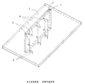
- L'invention sera mieux comprise à l'aide de la description suivante de la forme de réalisation préférée du bus-barre de l'invention, qui est représenté en perspective sur la figure unique du dessin annexé.
- Le bus-barre comporte une couche de cuivre 1 appartenant à une carte à circuit imprimé de forme allongée dont une couche isolante 2 porte la couche 1. Le bus-barre sert à distribuer un courant d'alimentation sur un support de composants électriques 3 qui le porte. Des barrettes métalliques 4, ici au nombre de trois, sont régulièrement espacées le long du bus-barre et assurent sa fixation sur le support 3 ainsi que la distribution du courant, provenant d'un connecteur non représenté du support 3 et relié à l'une des barrettes 4 par une liaison courte de forte section.
- Les barrettes 4 sont ici aplaties et disposées dans un plan perpendiculaire au plan de la carte 1-2 et à celui du support 3.
- Elles présentent ici deux ergots de soudage 5, sur un de leurs bords, qui traversent la couche 1 et y sont soudés. Deux autres ergots 6, ici sur un bord perpendiculaire au premier, sont de la même façon soudés à des pistes de distribution d'alimentation (non représentées) du support 3.
- Dans le présent exemple, la couche de cuivre a une épaisseur de 200 microns environ, ce qui offre une section élevée pour le passage du courant à distribuer, en conservant une largeur modérée (hauteur sur la figure) au bus-barre.
- En cas de besoin, on peut utiliser une carte de circuit imprimé multicouche et relier en parallèle, par des trous métallisés ou des fils de traversée, plusieurs des couches pour accroître la section du bus-barre.
- On peut aussi distribuer plusieurs courants isolés traversant chacun une ou quelques couches de cuivre.
- Avantageusement, on recouvre la ou les couches externes d'une couche à base d'étain pour augmenter encore la section tout en protégeant le cuivre contre l'oxydation.
Claims (6)
- Bus-barre plan de distribution d'alimentation électrique, caractérisé par le fait qu'il comporte un circuit imprimé (1) sur une carte (1, 2).
- Bus-barre selon la revendication 1, dans lequel le circuit imprimé (1, 2) est un circuit multicouche.
- Bus-barre selon la revendication 2, dans lequel le circuit multicouche (1, 2) est agencé pour distribuer plusieurs alimentations.
- Support de composants électriques (3) sur lequel est monté le bus-barre (1, 2) selon l'une des revendications 1 à 3, pour alimenter les composants par l'intermédiaire de barrettes de distribution (4) reliées au support (3) et au bus-barre (1-2).
- Barrette de distribution (4) pour relier le support de composants (3) de la revendication 4 au bus-barre (1,2) de l'une des revendications 1 à 3, caractérisée par le fait qu'elle comporte deux bords différents (5, 6) de liaison au support (3) et au bus-barre (1,2).
- Barrette selon la revendication 5, dans laquelle les deux bords de liaison (5, 6) sont perpendiculaires entre eux.
Applications Claiming Priority (2)
| Application Number | Priority Date | Filing Date | Title |
|---|---|---|---|
| FR9306908 | 1993-06-09 | ||
| FR9306908A FR2706726B1 (fr) | 1993-06-09 | 1993-06-09 | Bus-barre de distribution d'alimentation pour support de composants, ce support de composants et barrettes de distribution pour relier le bus-barre et le support. |
Publications (2)
| Publication Number | Publication Date |
|---|---|
| EP0629108A1 true EP0629108A1 (fr) | 1994-12-14 |
| EP0629108B1 EP0629108B1 (fr) | 1996-08-21 |
Family
ID=9447918
Family Applications (1)
| Application Number | Title | Priority Date | Filing Date |
|---|---|---|---|
| EP94401198A Expired - Lifetime EP0629108B1 (fr) | 1993-06-09 | 1994-05-31 | Bus-barre de distribution d'alimentation pour support de composants, ce support de composants et barrettes de distribution pour relier le bus-barre et le support |
Country Status (4)
| Country | Link |
|---|---|
| EP (1) | EP0629108B1 (fr) |
| AT (1) | ATE141742T1 (fr) |
| DE (1) | DE69400391T2 (fr) |
| FR (1) | FR2706726B1 (fr) |
Cited By (1)
| Publication number | Priority date | Publication date | Assignee | Title |
|---|---|---|---|---|
| CN106954343A (zh) * | 2017-04-14 | 2017-07-14 | 深圳市牧泰莱电路技术有限公司 | 一种厚导体层的母排电路板的制作方法 |
Families Citing this family (1)
| Publication number | Priority date | Publication date | Assignee | Title |
|---|---|---|---|---|
| FR3027645B1 (fr) | 2014-10-24 | 2018-03-02 | Aktiebolaget Skf | Dispositif de poulie pour chaine ou courroie et vehicule automobile equipe d'un tel dispositif |
Citations (2)
| Publication number | Priority date | Publication date | Assignee | Title |
|---|---|---|---|---|
| US4394532A (en) * | 1981-03-31 | 1983-07-19 | Rogers Corporation | Multilayer current distribution systems and methods of fabrication thereof |
| DE8813684U1 (de) * | 1988-11-02 | 1989-01-12 | kabelmetal electro GmbH, 3000 Hannover | Vorrichtung zur Befestigung einer Leiterkarte auf einer Schaltkarte |
-
1993
- 1993-06-09 FR FR9306908A patent/FR2706726B1/fr not_active Expired - Fee Related
-
1994
- 1994-05-31 DE DE69400391T patent/DE69400391T2/de not_active Expired - Fee Related
- 1994-05-31 AT AT94401198T patent/ATE141742T1/de not_active IP Right Cessation
- 1994-05-31 EP EP94401198A patent/EP0629108B1/fr not_active Expired - Lifetime
Patent Citations (2)
| Publication number | Priority date | Publication date | Assignee | Title |
|---|---|---|---|---|
| US4394532A (en) * | 1981-03-31 | 1983-07-19 | Rogers Corporation | Multilayer current distribution systems and methods of fabrication thereof |
| DE8813684U1 (de) * | 1988-11-02 | 1989-01-12 | kabelmetal electro GmbH, 3000 Hannover | Vorrichtung zur Befestigung einer Leiterkarte auf einer Schaltkarte |
Non-Patent Citations (1)
| Title |
|---|
| IBM TECHNICAL DISCLOSURE BULLETIN, vol. 24, no. 2, July 1981 (1981-07-01), pages 1239 - 1240 * |
Cited By (2)
| Publication number | Priority date | Publication date | Assignee | Title |
|---|---|---|---|---|
| CN106954343A (zh) * | 2017-04-14 | 2017-07-14 | 深圳市牧泰莱电路技术有限公司 | 一种厚导体层的母排电路板的制作方法 |
| CN106954343B (zh) * | 2017-04-14 | 2019-02-01 | 深圳市牧泰莱电路技术有限公司 | 一种厚导体层的母排电路板的制作方法 |
Also Published As
| Publication number | Publication date |
|---|---|
| DE69400391D1 (de) | 1996-09-26 |
| ATE141742T1 (de) | 1996-09-15 |
| DE69400391T2 (de) | 1997-03-06 |
| EP0629108B1 (fr) | 1996-08-21 |
| FR2706726B1 (fr) | 1995-08-04 |
| FR2706726A1 (fr) | 1994-12-23 |
Similar Documents
| Publication | Publication Date | Title |
|---|---|---|
| EP1376638B1 (fr) | Ensemble de protection et de commande électromagnétique | |
| EP2409554B1 (fr) | Boitier,raccord electrique incorporant ce boitier et vehicule incorporant ce raccord | |
| FR2681984A1 (fr) | Connecteur a jonctions multiples pour des installations de distribution electrique. | |
| EP1998406B1 (fr) | Dispositif de connexion électrique entre une source d'alimentation électrique et un radiateur électrique, et procédé de réalisation d'un tel dispositif de connexion. | |
| FR2776465A1 (fr) | Unite fonctionnelle de depart evolutive d'une cellule electrique a basse tension | |
| FR2529429A1 (fr) | Groupe d'appareils electriques montes sur un profile support commun | |
| FR2669179A1 (fr) | Appareil electrique, notamment appareil de commutation et de commande pour vehicules automobiles, et procede pour sa fabrication. | |
| FR2732183A1 (fr) | Systeme de remplacement de module connecte | |
| EP0629108B1 (fr) | Bus-barre de distribution d'alimentation pour support de composants, ce support de composants et barrettes de distribution pour relier le bus-barre et le support | |
| CA2348111A1 (fr) | Dispositif a contacts multiples pour les systemes de barres de bus de puissance | |
| FR2567691A1 (fr) | Barre omnibus pour montage en surface | |
| FR2489611A1 (fr) | Procede de fabrication d'un support d'affichage pour diode electroluminescente | |
| EP1014414B1 (fr) | Appareil électrique tel un disjoncteur ou un interrupteur modulaire | |
| EP0028791A1 (fr) | Barre d'alimentation électrique | |
| FR2750824A1 (fr) | Dispositif electrique de connexion et de securite, notamment pour le reseau de bord d'un vehicule automobile | |
| FR2803716A1 (fr) | Module electronique a composants de puissance et procede de fabrication | |
| EP1422799A1 (fr) | Dispositif de distribution d'énergie pour appareillages électriques | |
| FR2623030A1 (fr) | Dispositif d'alimentation electrique d'un support pour la fixation de materiel electrique et/ou electronique a un rail | |
| FR2802024A1 (fr) | Repartiteur modulaire monopolaire et bloc de connexion pour un tel repartiteur | |
| EP1371113B1 (fr) | Connecteur de puissance pour circuit imprime | |
| EP3561968B1 (fr) | Système de raccordement électrique pour transformateur de tension | |
| FR2697715A1 (fr) | Circuit imprimé double face et ensemble de conduction électrique comprenant un tel circuit imprimé. | |
| EP0828413A1 (fr) | Dispositif d'affichage électro-optique et support flexible pour de tels dispositifs servant à l'alimentation de ces dispositifs | |
| FR2848733A1 (fr) | Connecteur electrique pour raccordement d'un cable assurant la liaison electrique entre deux voitures d'un vehicule ferroviaire | |
| EP0119134B1 (fr) | Dispositif d'assemblage de composants électroniques de puissance sur un dissipateur thermique et application aux ponts monophasés ou polyphasés |
Legal Events
| Date | Code | Title | Description |
|---|---|---|---|
| PUAI | Public reference made under article 153(3) epc to a published international application that has entered the european phase |
Free format text: ORIGINAL CODE: 0009012 |
|
| AK | Designated contracting states |
Kind code of ref document: A1 Designated state(s): AT BE CH DE DK ES FR GB GR IE IT LI LU MC NL PT SE |
|
| 17P | Request for examination filed |
Effective date: 19950203 |
|
| 17Q | First examination report despatched |
Effective date: 19950919 |
|
| GRAH | Despatch of communication of intention to grant a patent |
Free format text: ORIGINAL CODE: EPIDOS IGRA |
|
| GRAH | Despatch of communication of intention to grant a patent |
Free format text: ORIGINAL CODE: EPIDOS IGRA |
|
| GRAA | (expected) grant |
Free format text: ORIGINAL CODE: 0009210 |
|
| AK | Designated contracting states |
Kind code of ref document: B1 Designated state(s): AT BE CH DE DK ES FR GB GR IE IT LI LU MC NL PT SE |
|
| PG25 | Lapsed in a contracting state [announced via postgrant information from national office to epo] |
Ref country code: NL Free format text: LAPSE BECAUSE OF FAILURE TO SUBMIT A TRANSLATION OF THE DESCRIPTION OR TO PAY THE FEE WITHIN THE PRESCRIBED TIME-LIMIT Effective date: 19960821 Ref country code: IT Free format text: LAPSE BECAUSE OF FAILURE TO SUBMIT A TRANSLATION OF THE DESCRIPTION OR TO PAY THE FEE WITHIN THE PRESCRIBED TIME-LIMIT;WARNING: LAPSES OF ITALIAN PATENTS WITH EFFECTIVE DATE BEFORE 2007 MAY HAVE OCCURRED AT ANY TIME BEFORE 2007. THE CORRECT EFFECTIVE DATE MAY BE DIFFERENT FROM THE ONE RECORDED. Effective date: 19960821 Ref country code: GR Free format text: LAPSE BECAUSE OF FAILURE TO SUBMIT A TRANSLATION OF THE DESCRIPTION OR TO PAY THE FEE WITHIN THE PRESCRIBED TIME-LIMIT Effective date: 19960821 Ref country code: GB Effective date: 19960821 Ref country code: ES Free format text: THE PATENT HAS BEEN ANNULLED BY A DECISION OF A NATIONAL AUTHORITY Effective date: 19960821 Ref country code: DK Effective date: 19960821 Ref country code: AT Effective date: 19960821 |
|
| REF | Corresponds to: |
Ref document number: 141742 Country of ref document: AT Date of ref document: 19960915 Kind code of ref document: T |
|
| REG | Reference to a national code |
Ref country code: IE Ref legal event code: FG4D Free format text: 69520 |
|
| REF | Corresponds to: |
Ref document number: 69400391 Country of ref document: DE Date of ref document: 19960926 |
|
| PG25 | Lapsed in a contracting state [announced via postgrant information from national office to epo] |
Ref country code: SE Effective date: 19961121 Ref country code: PT Effective date: 19961121 |
|
| NLV1 | Nl: lapsed or annulled due to failure to fulfill the requirements of art. 29p and 29m of the patents act | ||
| GBV | Gb: ep patent (uk) treated as always having been void in accordance with gb section 77(7)/1977 [no translation filed] |
Effective date: 19960821 |
|
| PG25 | Lapsed in a contracting state [announced via postgrant information from national office to epo] |
Ref country code: IE Free format text: LAPSE BECAUSE OF NON-PAYMENT OF DUE FEES Effective date: 19970416 |
|
| REG | Reference to a national code |
Ref country code: IE Ref legal event code: FD4D Ref document number: 69520 Country of ref document: IE |
|
| PG25 | Lapsed in a contracting state [announced via postgrant information from national office to epo] |
Ref country code: LU Free format text: LAPSE BECAUSE OF NON-PAYMENT OF DUE FEES Effective date: 19970531 Ref country code: LI Free format text: LAPSE BECAUSE OF NON-PAYMENT OF DUE FEES Effective date: 19970531 Ref country code: CH Free format text: LAPSE BECAUSE OF NON-PAYMENT OF DUE FEES Effective date: 19970531 Ref country code: BE Effective date: 19970531 |
|
| PLBE | No opposition filed within time limit |
Free format text: ORIGINAL CODE: 0009261 |
|
| STAA | Information on the status of an ep patent application or granted ep patent |
Free format text: STATUS: NO OPPOSITION FILED WITHIN TIME LIMIT |
|
| 26N | No opposition filed | ||
| BERE | Be: lapsed |
Owner name: SOC. D'APPLICATIONS GENERALES D'ELECTRICITE ET DE Effective date: 19970531 |
|
| PG25 | Lapsed in a contracting state [announced via postgrant information from national office to epo] |
Ref country code: MC Effective date: 19971130 |
|
| REG | Reference to a national code |
Ref country code: CH Ref legal event code: PL |
|
| PG25 | Lapsed in a contracting state [announced via postgrant information from national office to epo] |
Ref country code: FR Free format text: LAPSE BECAUSE OF NON-PAYMENT OF DUE FEES Effective date: 19980130 |
|
| REG | Reference to a national code |
Ref country code: FR Ref legal event code: ST |
|
| PGFP | Annual fee paid to national office [announced via postgrant information from national office to epo] |
Ref country code: DE Payment date: 20080531 Year of fee payment: 15 |
|
| PG25 | Lapsed in a contracting state [announced via postgrant information from national office to epo] |
Ref country code: DE Free format text: LAPSE BECAUSE OF NON-PAYMENT OF DUE FEES Effective date: 20091201 |