EP0629460A1 - Stahlschneidvorrichtung - Google Patents
Stahlschneidvorrichtung Download PDFInfo
- Publication number
- EP0629460A1 EP0629460A1 EP93306019A EP93306019A EP0629460A1 EP 0629460 A1 EP0629460 A1 EP 0629460A1 EP 93306019 A EP93306019 A EP 93306019A EP 93306019 A EP93306019 A EP 93306019A EP 0629460 A1 EP0629460 A1 EP 0629460A1
- Authority
- EP
- European Patent Office
- Prior art keywords
- shearing
- blades
- blade
- mid point
- steel material
- Prior art date
- Legal status (The legal status is an assumption and is not a legal conclusion. Google has not performed a legal analysis and makes no representation as to the accuracy of the status listed.)
- Granted
Links
- 238000010008 shearing Methods 0.000 title claims abstract description 125
- 229910000831 Steel Inorganic materials 0.000 title claims description 52
- 239000010959 steel Substances 0.000 title claims description 52
- 239000000463 material Substances 0.000 title claims description 50
- 238000010276 construction Methods 0.000 description 5
- 229910000851 Alloy steel Inorganic materials 0.000 description 1
- 238000013459 approach Methods 0.000 description 1
- 239000006185 dispersion Substances 0.000 description 1
- 230000000694 effects Effects 0.000 description 1
- 239000011150 reinforced concrete Substances 0.000 description 1
- 230000003014 reinforcing effect Effects 0.000 description 1
- 239000000126 substance Substances 0.000 description 1
Images


Classifications
-
- B—PERFORMING OPERATIONS; TRANSPORTING
- B23—MACHINE TOOLS; METAL-WORKING NOT OTHERWISE PROVIDED FOR
- B23D—PLANING; SLOTTING; SHEARING; BROACHING; SAWING; FILING; SCRAPING; LIKE OPERATIONS FOR WORKING METAL BY REMOVING MATERIAL, NOT OTHERWISE PROVIDED FOR
- B23D35/00—Tools for shearing machines or shearing devices; Holders or chucks for shearing tools
- B23D35/001—Tools for shearing machines or shearing devices; Holders or chucks for shearing tools cutting members
-
- B—PERFORMING OPERATIONS; TRANSPORTING
- B23—MACHINE TOOLS; METAL-WORKING NOT OTHERWISE PROVIDED FOR
- B23D—PLANING; SLOTTING; SHEARING; BROACHING; SAWING; FILING; SCRAPING; LIKE OPERATIONS FOR WORKING METAL BY REMOVING MATERIAL, NOT OTHERWISE PROVIDED FOR
- B23D17/00—Shearing machines or shearing devices cutting by blades pivoted on a single axis
-
- Y—GENERAL TAGGING OF NEW TECHNOLOGICAL DEVELOPMENTS; GENERAL TAGGING OF CROSS-SECTIONAL TECHNOLOGIES SPANNING OVER SEVERAL SECTIONS OF THE IPC; TECHNICAL SUBJECTS COVERED BY FORMER USPC CROSS-REFERENCE ART COLLECTIONS [XRACs] AND DIGESTS
- Y10—TECHNICAL SUBJECTS COVERED BY FORMER USPC
- Y10S—TECHNICAL SUBJECTS COVERED BY FORMER USPC CROSS-REFERENCE ART COLLECTIONS [XRACs] AND DIGESTS
- Y10S83/00—Cutting
- Y10S83/928—Vehicle-mounted tool
Definitions
- This invention relates to a shearing machine mounted on a tip of an arm of a working machine, such as a power shovel, for shearing a various kinds of steel material.
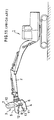
- a power shovel 1 shown in Fig. 11 When de-constructing or destroying reinforcing bars, buildings of a reinforced concrete construction, scraps of steel article or chemical machinery of steel alloy, a power shovel 1 shown in Fig. 11 is used.
- the power shovel includes an arm 2 mounted with a steel material shearing machine 3 at the tip end thereof.
- a conventional steel material shearing machine 3 includes a lower jaw 4 and an upper jaw 5.
- the upper jaw 5 is pivotably connected at the root portion thereof to the rearward portion of the lower jaw 4 by means of a support shaft 6.
- the upper jaw 5 and the lower jaw 4 are adapted to be opened and closed, in a scissors-like manner, relative to one another by means of a hydraulic cylinder disposed between a frame 7 extending from the lower jaw 4 and the upper jaw 5.
- the lower jaw 4 and the upper jaw 5 include their respective shearing blades 11, 12 attached to their respective inner surfaces adapted to be slidably engaged with each other.
- the lower shearing blade 11 attached to the lower jaw 4 and the upper shearing blade 12 attached to the upper jaw 5 are bent at their respective mid points 9 outwardly in the open-close direction of the jaws.
- the steel material shearing machine 3 shears or cuts a steel material 13 clamped between the lower jaw 4 and the upper jaw 5 when the jaws are moved relative one another in a crossing manner. That is to say, the shearing blades 11, 12 attached to the lower and upper jaws, respectively, serve to shear the steel material 13 in both forward and rearward directions, while preventing slippage of the steel material 13 by reason of the outwardly displaced mid points 9.
- the rearward blade portion positioned rearwardly of the mid point 9 of each of the lower shearing blade 11 and the upper shearing blade 12 has an angle smaller than that of the forward blade portion.
- a cross-angle defined between the steel material and the lower and upper shearing blades 11, 12 becomes smaller as a shearing point of the steel material approaches the respective mid points 9, so that shearing ability is reduced at a position adjacent to the mid points 9.
- U. S. Patent No. 4519135 discloses a construction in which a side plate is provided with the lower jaw for guiding of the outer side of the upper jaw, whereby the upper jaw is disposed between the lower jaw and the side plate, thus preventing the "mouth opening” phenomenon.
- the shearing machine 3 includes a plurality of lower shearing blades 14, 15 attached to the lower jaw 4.
- the forward, lower shearing blade (hereinafter referred to as "lower leading blade”) 14 and rearward, lower shearing blade (hereinafter referred to as “lower trailing blade”) 15 are angled with each other in a V-shaped configuration and staggered relative to one another with respect to the shearing plane as shown in the drawings.
- the upper jaw 5 also includes a plurality of upper shearing blades 16, 17 attached thereto.
- the forward, upper shearing blade (hereinafter referred to as “upper leading blade”) 16 and the rearward, upper shearing blade (hereinafter referred to as “upper trailing blade”) are angled with each other in an inverted V-shaped configuration and staggered relative to one another with respect to the shearing plane.
- the shearing machine 3 is swivelably mounted on a base frame 20 adapted to be attached to the arm. Thus, the shearing machine 3 is swivelable relative to the base frame 20 by means of an appropriate driving means (not shown).
- the above shearing machine 3 has a high shearing ability
- the lower leading blade 14 and the lower trailing blade 15 are leveled with each other at the mid point 9
- the upper leading blade 16 and the upper trailing blade 17 are also leveled with each other at the mid point 9.
- a steel plate 13 of a significant width is sheared from opposite sides or ends thereof, at the same time, due to the interengagement of the lower leading blade 14 and the upper leading blade 16, and the interengagement of the lower trailing blade 15 and the upper trailing blade 17.
- the shearing ability is reduced in an area adjacent to the mid point 9.
- the shearing action of the lower leading blade 14 and the upper leading blade 16 precedes as shown in Fig. 14, so that, when shearing action proceeds to an curved area adjacent to the mid point, as shown in Figs.
- the steel material 13 is clamped between the root portion or rearward portions of the lower leading blade 14 and the upper leading blade 16, and the forward end portions of the lower trailing blade 15 and the upper trailing blade 17.
- the upper and lower surfaces of the blades become substantially in flush with the upper and lower surfaces of the steel material adjacent to the mid point, respectively.
- shearing force to be exerted to the steel material is not concentrated to the edge of the lower trailing blade 15 and the upper trailing blade 17 but is dispersed to the surface of the blades substantially in flush with the surfaces of the steel material. Accordingly, it is not possible for a hydraulic cylinder 10 of a normal power to proceed with further shearing action for completely cutting the steel material 13.
- a steel material shearing machine which comprises a lower jaw and an upper jaw adapted to be opened and closed in a crossing manner with each other, and a lower shearing blade and an upper shearing blade attached to the lower and upper jaws, respectively, each of the shearing blades being angled, at a mid point along the longitudinal direction of the blades, outwardly in the open-close direction of the jaws, wherein each of the blades are further angled, at least at a portion rearward of the mid point, outwardly in the open-close direction so as to form an offset at a position adjacent to the mid point.
- the invention also provides a steel material shearing machine which comprises a lower jaw and an upper jaw adapted to be opened and closed in a crossing manner with each other, and a lower shearing blade and an upper shearing blade attached to the lower and upper jaws, respectively, each of the shearing blades being angled, at a mid point along the longitudinal direction of the blades, outwardly in the open-close direction of the jaws, each of the blades being arranged in a staggered fashion so that the forward portion forward of the mid point and the rearward portion rearward of the mid point of each of the blades are disposed in opposite sides of the shearing plane, wherein each of the blades are further angled, at least at a portion rearward of the mid point, outwardly in the open-close direction so as to form an offset at a position adjacent to the mid point.
- one of the blades is formed with a gap at a position rearward of the mid point, while the other of the blades is formed with a gap at a position forward of the mid point.
- the lower trailing blade and the upper trailing blade form a steep angle due to their inclination, so that an increased cross-angle relative to the steel material can be obtained at least at a portion adjacent to the mid point. Furthermore, and with respect to shearing action adjacent to the mid point, shearing action of the leading blades precedes, and followed by the shearing action of the trailing blades, so that dispersion of a shearing force can be prevented, thus facilitating secure shearing of the steel material extending across the mid point.
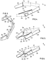
- Fig. 1 is a side elevational view of a steel material shearing machine according to the invention with the jaws in an open position.
- Fig. 2 is a side elevational view of the shearing machine with the jaws in a closed position.
- Fig. 3 is a perspective view illustrating spatial relationship between the shearing blades of the shearing machine.
- Fig. 4 is a diagrammatic illustrative view showing a first step of shearing mechanism of the shearing machine.
- Fig. 5 is a diagrammatic illustrative view showing a second step of shearing mechanism of the shearing machine.
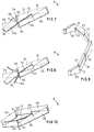
- Fig. 6 is a diagrammatic illustrative view showing a third step of shearing mechanism of the shearing machine.
- Fig. 7 is a diagrammatic illustrative view showing a fourth step of shearing mechanism of the shearing machine.
- Fig. 8 is a diagrammatic illustrative view showing a fifth step of shearing mechanism of the shearing machine
- Fig. 9 is a perspective view illustrating spatial relationship between the blades of an alternative steel material shearing machine.
- Fig. 10 is a diagrammatic illustrative view showing shearing mechanism of the shearing machine of Fig. 9.
- Fig. 11 is side elevational view of a power shovel mounted with a conventional steel material shearing machine.
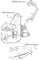
- Fig. 12 is a side elevational view of the conventional shearing machine.
- Fig. 13 is a perspective view illustrating spatial relationship between the blades of the conventional shearing machine.
- Fig. 14 is a diagrammatic illustrative view showing a first step of shearing mechanism of the conventional shearing machine.
- Fig. 15 is a diagrammatic illustrative view showing a second step of shearing mechanism of the conventional shearing machine.
- Fig. 16 is a diagrammatic illustrative view showing a third step of shearing mechanism of the conventional shearing machine.
- Fig. 17 is a plan view illustrating inconvenience experienced in the conventional shearing machine.
- Figs. 1 through 10 Several embodiments according to the invention will be explained below with reference to Figs. 1 through 10. It is noted that like elements are designated by the same references in the prior art and omitted from explanation. It is also noted that, in Figs. 4 through 8, the blades positioned in front of the shearing plane are shown by solid lines, while the blades positioned backward of the shearing plane are shown by dashed lines.
- a lower leading blade 24 and a lower trailing blade 25 attached to a lower jaw 4 are arranged in staggered fashion relative to one another with respect to the shearing plane.
- the forward end of the lower trailing blade 25 is angled outwardly in the open-close direction so as to form an offset 26 in relation to the rearward end of the lower leading blade 24, thus forming a saw blade-like configuration.
- an upper leading blade 30 and an upper trailing blade 31 attached to an upper jaw 5 are arranged in a staggered fashion relative to one another with respect to the shearing plane.
- the tip end or forward end of the upper trailing blade 31 is angled outwardly in the open-close direction so as to form an offset 32 in relation to the rearward end of the upper leading blade 30, thus forming a saw blade-like configuration.
- the tip end or forward end of the upper trailing blade 31 is displaced rearwardly from the mid point 34 so as to form a gap 33 in relation to the rearward end of the upper leading blade 30.
- the rearward end of the lower leading blade 24 is displaced forwardly from the mid point 34 so as to form a gap 27 in relation to the tip end or forward end of the lower trailing blade 25.
- the forward end of a lower trailing blade 36, attached to the lower jaw (not shown) at a position rearwardly of the mid point 34 can be angled outwardly so as to form an offset 37 in relation to the rearward end of a lower leading blade 35.
- An upper trailing blade 41, attached to the upper jaw (not shown) at a position rearwardly of the mid point 34 is also angled outwardly so as to form an offset 42 in relation to the rearward end of the upper leading blade 40.
- the lower trailing blade 36 and the upper trailing blade also have a steep angle. Furthermore, the cross angle or intersection angle relative to the steel material adjacent to the mid point 34 is increased. Accordingly, shearing ability will not be reduced until final point.
Landscapes
- Engineering & Computer Science (AREA)
- Mechanical Engineering (AREA)
- Working Measures On Existing Buildindgs (AREA)
Applications Claiming Priority (2)
| Application Number | Priority Date | Filing Date | Title |
|---|---|---|---|
| JP144448/93 | 1993-06-16 | ||
| JP5144448A JP2632486B2 (ja) | 1993-06-16 | 1993-06-16 | 鋼材剪断機 |
Publications (2)
| Publication Number | Publication Date |
|---|---|
| EP0629460A1 true EP0629460A1 (de) | 1994-12-21 |
| EP0629460B1 EP0629460B1 (de) | 1998-09-23 |
Family
ID=15362473
Family Applications (1)
| Application Number | Title | Priority Date | Filing Date |
|---|---|---|---|
| EP93306019A Expired - Lifetime EP0629460B1 (de) | 1993-06-16 | 1993-07-29 | Stahlschneidvorrichtung |
Country Status (4)
| Country | Link |
|---|---|
| US (1) | US5471747A (de) |
| EP (1) | EP0629460B1 (de) |
| JP (1) | JP2632486B2 (de) |
| DE (1) | DE69321220T2 (de) |
Cited By (6)
| Publication number | Priority date | Publication date | Assignee | Title |
|---|---|---|---|---|
| EP0678354A1 (de) * | 1994-04-18 | 1995-10-25 | OHYODO DIESEL CO., Ltd. | Stahlschneidevorrichtung |
| EP0760268A1 (de) * | 1995-08-28 | 1997-03-05 | OHYODO DIESEL CO., Ltd. | Scherenartiges Gerät zum Scheren von Stahl mit sich senkrecht bewegenden, im Winkel gekippten und aus querversetzten zusammenwirkenden Teilen bestehenden Schreibzonen |
| EP0768137A1 (de) * | 1995-10-11 | 1997-04-16 | OHYODO DIESEL CO., Ltd. | Stahlschneidvorrichtung mit polygonale Messern |
| US5669141A (en) * | 1993-06-16 | 1997-09-23 | Ohyodo Diesel Co., Ltd. | Scissors type steel shearing apparatus with vertically displaced and angularly tilted shearing zones and transversely displaced interlocking portions |
| US5749146A (en) * | 1993-06-16 | 1998-05-12 | Ohyodo Diesel Co., Ltd. | Scissors type steel shearing apparatus with polygonal shearing blades |
| EP2672018A1 (de) * | 2012-06-05 | 2013-12-11 | Seung Hwan Ko | Klingenpositionierungsstruktur für eine Schere für eine Arbeitsmaschine |
Families Citing this family (14)
| Publication number | Priority date | Publication date | Assignee | Title |
|---|---|---|---|---|
| JP2655817B2 (ja) * | 1994-10-13 | 1997-09-24 | 大淀ヂ−ゼル株式会社 | 剪断機 |
| JP3058247B2 (ja) * | 1995-08-24 | 2000-07-04 | 大淀ヂ−ゼル株式会社 | 鎌型剪断機 |
| US6047475A (en) * | 1998-02-26 | 2000-04-11 | Nippon Pneumatic Mfg. Co. Ltd. | Mounting for a construction shear |
| DK1392463T3 (da) * | 2001-05-11 | 2005-11-21 | Brian Purser | Brydningsanordning |
| US8146256B2 (en) | 2003-10-31 | 2012-04-03 | Stanley Black & Decker, Inc. | Metal demolition shears with indexable, integrated wear plate/piercing tip |
| US20070145171A1 (en) * | 2005-12-23 | 2007-06-28 | The Stanley Works | Rebar cutting shears |
| US7832130B2 (en) * | 2006-10-06 | 2010-11-16 | The Stanley Works | Multiple mounting bracket for a mobile processor attachment mounted on a hydraulic excavator |
| JP2011064025A (ja) * | 2009-09-18 | 2011-03-31 | Towani:Kk | 切断装置及び該切断装置を備えた解体作業車 |
| US20110225829A1 (en) * | 2010-03-22 | 2011-09-22 | Genesis Attachments, Llc | Heavy duty configurable shear crusher demolition tool |
| US20140331843A1 (en) * | 2013-03-14 | 2014-11-13 | Charlie Hall | System of indexable cutting portions for a shear |
| US9470015B2 (en) * | 2013-08-16 | 2016-10-18 | Curtis Hull | Multi-purpose grasping attachment |
| US9518405B2 (en) * | 2013-08-16 | 2016-12-13 | Curtis Hull | Multi-purpose grasping attachment accessory |
| FI126476B (fi) * | 2015-11-12 | 2016-12-30 | Ramtec Oy | Kannonnostolaite, järjestelmä ja menetelmä kannon nostamiseksi |
| US10918026B2 (en) * | 2017-04-25 | 2021-02-16 | National Attachments Incorporated | Optimized stump harvester |
Citations (3)
| Publication number | Priority date | Publication date | Assignee | Title |
|---|---|---|---|---|
| DE940442C (de) * | 1954-04-23 | 1956-03-15 | Alois Rohbogner | Zackenfoermiges Messer, insbesondere zum Querschneiden von metallischen Folien |
| US3523365A (en) * | 1968-05-31 | 1970-08-11 | United States Steel Corp | Portable shear |
| US5187868A (en) * | 1992-06-16 | 1993-02-23 | Hall Charlie R | Metal demolition shear |
Family Cites Families (10)
| Publication number | Priority date | Publication date | Assignee | Title |
|---|---|---|---|---|
| US3626477A (en) * | 1969-10-30 | 1971-12-07 | Fulghum Enterprises Inc | Timber shear |
| US4519135A (en) * | 1982-09-13 | 1985-05-28 | Labounty Roy E | Metal demolition shear |
| US4771540A (en) * | 1982-09-13 | 1988-09-20 | Labounty Roy E | Metal grapple shear |
| US4616417A (en) * | 1985-01-07 | 1986-10-14 | Aaa Steel And Enterprises Corp. | Hydraulic shear head attachment for backhoe or the like |
| JPS61294023A (ja) * | 1985-06-22 | 1986-12-24 | Sango Juki:Kk | 鉄骨材の切断装置 |
| JPH062188Y2 (ja) * | 1986-07-04 | 1994-01-19 | 三菱電機株式会社 | 釈放形電磁装置 |
| US5179985A (en) * | 1990-04-13 | 1993-01-19 | Olli Pallari | Lifting and crushing apparatus for tree stumps |
| JPH079970Y2 (ja) * | 1991-05-20 | 1995-03-08 | 大淀小松株式会社 | 鉄骨切断機 |
| US5224268A (en) * | 1992-04-20 | 1993-07-06 | Pemberton, Inc. | Apparatus for shearing a material mass |
| US5291657A (en) * | 1992-10-12 | 1994-03-08 | Ohyodo Diesel Co., Ltd. | Shearing machine for steel material |
-
1993
- 1993-06-16 JP JP5144448A patent/JP2632486B2/ja not_active Expired - Fee Related
- 1993-07-29 DE DE69321220T patent/DE69321220T2/de not_active Expired - Fee Related
- 1993-07-29 EP EP93306019A patent/EP0629460B1/de not_active Expired - Lifetime
- 1993-08-03 US US08/101,358 patent/US5471747A/en not_active Expired - Fee Related
Patent Citations (3)
| Publication number | Priority date | Publication date | Assignee | Title |
|---|---|---|---|---|
| DE940442C (de) * | 1954-04-23 | 1956-03-15 | Alois Rohbogner | Zackenfoermiges Messer, insbesondere zum Querschneiden von metallischen Folien |
| US3523365A (en) * | 1968-05-31 | 1970-08-11 | United States Steel Corp | Portable shear |
| US5187868A (en) * | 1992-06-16 | 1993-02-23 | Hall Charlie R | Metal demolition shear |
Cited By (7)
| Publication number | Priority date | Publication date | Assignee | Title |
|---|---|---|---|---|
| US5669141A (en) * | 1993-06-16 | 1997-09-23 | Ohyodo Diesel Co., Ltd. | Scissors type steel shearing apparatus with vertically displaced and angularly tilted shearing zones and transversely displaced interlocking portions |
| US5749146A (en) * | 1993-06-16 | 1998-05-12 | Ohyodo Diesel Co., Ltd. | Scissors type steel shearing apparatus with polygonal shearing blades |
| EP0678354A1 (de) * | 1994-04-18 | 1995-10-25 | OHYODO DIESEL CO., Ltd. | Stahlschneidevorrichtung |
| US5626301A (en) * | 1994-04-18 | 1997-05-06 | Ohyodo Diesel Co., Ltd. | Steel material shearing machine |
| EP0760268A1 (de) * | 1995-08-28 | 1997-03-05 | OHYODO DIESEL CO., Ltd. | Scherenartiges Gerät zum Scheren von Stahl mit sich senkrecht bewegenden, im Winkel gekippten und aus querversetzten zusammenwirkenden Teilen bestehenden Schreibzonen |
| EP0768137A1 (de) * | 1995-10-11 | 1997-04-16 | OHYODO DIESEL CO., Ltd. | Stahlschneidvorrichtung mit polygonale Messern |
| EP2672018A1 (de) * | 2012-06-05 | 2013-12-11 | Seung Hwan Ko | Klingenpositionierungsstruktur für eine Schere für eine Arbeitsmaschine |
Also Published As
| Publication number | Publication date |
|---|---|
| JP2632486B2 (ja) | 1997-07-23 |
| EP0629460B1 (de) | 1998-09-23 |
| DE69321220D1 (de) | 1998-10-29 |
| DE69321220T2 (de) | 1999-05-06 |
| JPH074071A (ja) | 1995-01-10 |
| US5471747A (en) | 1995-12-05 |
Similar Documents
| Publication | Publication Date | Title |
|---|---|---|
| EP0629460B1 (de) | Stahlschneidvorrichtung | |
| EP1163079B1 (de) | Schrottzerkleinerungsvorrichtung mit auswechselbaren scherleisten und brechzähnen | |
| JP2655817B2 (ja) | 剪断機 | |
| US6061911A (en) | Heavy-duty demolition apparatus with blade stabilizing device | |
| US5384962A (en) | Apparatus for shearing a material mass | |
| JP2556664B2 (ja) | 鋼材剪断機 | |
| JPH0321283B2 (de) | ||
| CN1052438A (zh) | 岩石和珊瑚破碎器 | |
| US4457085A (en) | Excavating buckets | |
| US5860214A (en) | Shearing machine with sickle-shaped blade | |
| NL8302636A (nl) | Hulpstuk voor een graafmachine of dergelijke. | |
| JPH11505772A (ja) | 鋼構造体用剪断機 | |
| EP2578776A1 (de) | Demontage- und schneidemaschine | |
| EP0137693B1 (de) | Abschervorrichtung für Stahlrahmen | |
| US5291657A (en) | Shearing machine for steel material | |
| EP0768137B1 (de) | Stahlschneidvorrichtung mit polygonalen Messern | |
| JPH0227504B2 (de) | ||
| EP0634242B1 (de) | Ausstanzähnliche Schneidvorrichtung | |
| JP4009395B2 (ja) | 高信頼性プレ−ト切断特性を有する大型解体剪断機 | |
| US5890667A (en) | Crushing machine | |
| EP0592722B1 (de) | Schere für Stahlmaterial | |
| US5749146A (en) | Scissors type steel shearing apparatus with polygonal shearing blades | |
| JP2007330870A (ja) | 破砕機 | |
| JPH0144270Y2 (de) | ||
| JP3039317U (ja) | 破砕機 |
Legal Events
| Date | Code | Title | Description |
|---|---|---|---|
| PUAI | Public reference made under article 153(3) epc to a published international application that has entered the european phase |
Free format text: ORIGINAL CODE: 0009012 |
|
| AK | Designated contracting states |
Kind code of ref document: A1 Designated state(s): DE FR GB IT NL |
|
| 17P | Request for examination filed |
Effective date: 19950215 |
|
| 17Q | First examination report despatched |
Effective date: 19961112 |
|
| GRAG | Despatch of communication of intention to grant |
Free format text: ORIGINAL CODE: EPIDOS AGRA |
|
| GRAG | Despatch of communication of intention to grant |
Free format text: ORIGINAL CODE: EPIDOS AGRA |
|
| GRAG | Despatch of communication of intention to grant |
Free format text: ORIGINAL CODE: EPIDOS AGRA |
|
| GRAH | Despatch of communication of intention to grant a patent |
Free format text: ORIGINAL CODE: EPIDOS IGRA |
|
| GRAH | Despatch of communication of intention to grant a patent |
Free format text: ORIGINAL CODE: EPIDOS IGRA |
|
| ITF | It: translation for a ep patent filed | ||
| GRAA | (expected) grant |
Free format text: ORIGINAL CODE: 0009210 |
|
| AK | Designated contracting states |
Kind code of ref document: B1 Designated state(s): DE FR GB IT NL |
|
| REF | Corresponds to: |
Ref document number: 69321220 Country of ref document: DE Date of ref document: 19981029 |
|
| ET | Fr: translation filed | ||
| PLBE | No opposition filed within time limit |
Free format text: ORIGINAL CODE: 0009261 |
|
| STAA | Information on the status of an ep patent application or granted ep patent |
Free format text: STATUS: NO OPPOSITION FILED WITHIN TIME LIMIT |
|
| 26N | No opposition filed | ||
| PGFP | Annual fee paid to national office [announced via postgrant information from national office to epo] |
Ref country code: FR Payment date: 20010712 Year of fee payment: 9 |
|
| PGFP | Annual fee paid to national office [announced via postgrant information from national office to epo] |
Ref country code: DE Payment date: 20010723 Year of fee payment: 9 |
|
| PGFP | Annual fee paid to national office [announced via postgrant information from national office to epo] |
Ref country code: GB Payment date: 20010725 Year of fee payment: 9 |
|
| PGFP | Annual fee paid to national office [announced via postgrant information from national office to epo] |
Ref country code: NL Payment date: 20010730 Year of fee payment: 9 |
|
| REG | Reference to a national code |
Ref country code: GB Ref legal event code: IF02 |
|
| PG25 | Lapsed in a contracting state [announced via postgrant information from national office to epo] |
Ref country code: GB Free format text: LAPSE BECAUSE OF NON-PAYMENT OF DUE FEES Effective date: 20020729 |
|
| PG25 | Lapsed in a contracting state [announced via postgrant information from national office to epo] |
Ref country code: NL Free format text: LAPSE BECAUSE OF NON-PAYMENT OF DUE FEES Effective date: 20030201 Ref country code: DE Free format text: LAPSE BECAUSE OF NON-PAYMENT OF DUE FEES Effective date: 20030201 |
|
| GBPC | Gb: european patent ceased through non-payment of renewal fee |
Effective date: 20020729 |
|
| PG25 | Lapsed in a contracting state [announced via postgrant information from national office to epo] |
Ref country code: FR Free format text: LAPSE BECAUSE OF NON-PAYMENT OF DUE FEES Effective date: 20030331 |
|
| NLV4 | Nl: lapsed or anulled due to non-payment of the annual fee |
Effective date: 20030201 |
|
| REG | Reference to a national code |
Ref country code: FR Ref legal event code: ST |
|
| PG25 | Lapsed in a contracting state [announced via postgrant information from national office to epo] |
Ref country code: IT Free format text: LAPSE BECAUSE OF NON-PAYMENT OF DUE FEES;WARNING: LAPSES OF ITALIAN PATENTS WITH EFFECTIVE DATE BEFORE 2007 MAY HAVE OCCURRED AT ANY TIME BEFORE 2007. THE CORRECT EFFECTIVE DATE MAY BE DIFFERENT FROM THE ONE RECORDED. Effective date: 20050729 |