EP0629803A1 - Agencement de soupape de surpression - Google Patents
Agencement de soupape de surpression Download PDFInfo
- Publication number
- EP0629803A1 EP0629803A1 EP94303889A EP94303889A EP0629803A1 EP 0629803 A1 EP0629803 A1 EP 0629803A1 EP 94303889 A EP94303889 A EP 94303889A EP 94303889 A EP94303889 A EP 94303889A EP 0629803 A1 EP0629803 A1 EP 0629803A1
- Authority
- EP
- European Patent Office
- Prior art keywords
- valve
- valve element
- arrangement according
- pressure relief
- primary
- Prior art date
- Legal status (The legal status is an assumption and is not a legal conclusion. Google has not performed a legal analysis and makes no representation as to the accuracy of the status listed.)
- Withdrawn
Links
- 238000003860 storage Methods 0.000 claims abstract description 26
- XLYOFNOQVPJJNP-UHFFFAOYSA-N water Substances O XLYOFNOQVPJJNP-UHFFFAOYSA-N 0.000 claims abstract description 11
- 238000013022 venting Methods 0.000 claims abstract description 8
- 239000007788 liquid Substances 0.000 claims abstract description 4
- 238000007789 sealing Methods 0.000 claims description 12
- 238000007373 indentation Methods 0.000 claims description 5
- 229910000831 Steel Inorganic materials 0.000 description 7
- 238000007710 freezing Methods 0.000 description 7
- 230000008014 freezing Effects 0.000 description 7
- 239000010959 steel Substances 0.000 description 7
- 238000009833 condensation Methods 0.000 description 5
- 230000005494 condensation Effects 0.000 description 5
- 230000008020 evaporation Effects 0.000 description 5
- 238000001704 evaporation Methods 0.000 description 5
- 239000011324 bead Substances 0.000 description 4
- 238000005429 filling process Methods 0.000 description 3
- 239000012530 fluid Substances 0.000 description 3
- 239000003209 petroleum derivative Substances 0.000 description 3
- 238000001816 cooling Methods 0.000 description 2
- 230000001419 dependent effect Effects 0.000 description 2
- 230000000694 effects Effects 0.000 description 2
- 230000007613 environmental effect Effects 0.000 description 2
- 238000005266 casting Methods 0.000 description 1
- 238000010276 construction Methods 0.000 description 1
- 230000003247 decreasing effect Effects 0.000 description 1
- 239000002360 explosive Substances 0.000 description 1
- 239000002828 fuel tank Substances 0.000 description 1
- 238000003754 machining Methods 0.000 description 1
- 238000004519 manufacturing process Methods 0.000 description 1
- 238000000034 method Methods 0.000 description 1
- 239000003208 petroleum Substances 0.000 description 1
- 238000007666 vacuum forming Methods 0.000 description 1
Images
Classifications
-
- F—MECHANICAL ENGINEERING; LIGHTING; HEATING; WEAPONS; BLASTING
- F16—ENGINEERING ELEMENTS AND UNITS; GENERAL MEASURES FOR PRODUCING AND MAINTAINING EFFECTIVE FUNCTIONING OF MACHINES OR INSTALLATIONS; THERMAL INSULATION IN GENERAL
- F16K—VALVES; TAPS; COCKS; ACTUATING-FLOATS; DEVICES FOR VENTING OR AERATING
- F16K1/00—Lift valves or globe valves, i.e. cut-off apparatus with closure members having at least a component of their opening and closing motion perpendicular to the closing faces
- F16K1/32—Details
-
- F—MECHANICAL ENGINEERING; LIGHTING; HEATING; WEAPONS; BLASTING
- F16—ENGINEERING ELEMENTS AND UNITS; GENERAL MEASURES FOR PRODUCING AND MAINTAINING EFFECTIVE FUNCTIONING OF MACHINES OR INSTALLATIONS; THERMAL INSULATION IN GENERAL
- F16K—VALVES; TAPS; COCKS; ACTUATING-FLOATS; DEVICES FOR VENTING OR AERATING
- F16K17/00—Safety valves; Equalising valves, e.g. pressure relief valves
- F16K17/18—Safety valves; Equalising valves, e.g. pressure relief valves opening on surplus pressure on either side
- F16K17/19—Equalising valves predominantly for tanks
- F16K17/194—Equalising valves predominantly for tanks weight-loaded
Definitions
- This invention relates to a pressure relief valve, and more particularly to a pressure relief valve arrangement for fitting to storage tanks of volatile liquids for venting of the storage tank.
- vent pipe which has a discharge point well above ground level.
- vent pipes are normally fitted with an updraft vent cowl which directs the vapours upwardly and away from the discharge point of the vent pipe.
- updraft vent cowls particularly where the cowl is situated in a windy location, often result in a slight vacuum being drawn on the storage container. This then causes continuous outward flow and further evaporation of fluid from within the storage tank.
- valve arrangement typically comprises both a positive pressure relief valve and a vacuum relief valve.
- the positive pressure relief valve comprises a weighted ball seating on a sealing surface. Should a build up of pressure occur within the storage tank, the ball is designed to lift away from the sealing surface at a predetermined pressure, dependent on the weight of the ball, thereby relieving pressure within the tank.
- the vacuum relief valve allows atmospheric air to flow into the storage tank should a vacuum be created.
- the second valve comprises a plate again seating on a sealing surface, which plate will lift in the event of a vacuum existing within the storage tank.
- the known valve arrangement therefore provides a means of preventing build up of a vacuum in the storage tank as it is emptied, while at the same time allowing excessive pressure resulting from evaporation to be vented, and also at the same time allowing air to be discharged during the fill-in process.
- This condensation can, in fact, due to the shape of the primary valve element, gather in the vicinity of the sealing surface, and if the environmental conditions are cold enough, or if the vapour movement itself has resulted in rapid cooling, then this condensate may in fact freeze, thereby effectively fixing the valve body to the seat. Clearly, in the circumstances, the valve may fail to operate at the required pressure.
- a further object of this invention is to provide for efficient drainage at the primary valve, including minor amounts of condensation.
- the present invention also aims to provide a solution to this problem.
- a drainage channel which surrounds the primary valve element to allow water flow from any point around the valve element to exit from a single drainage aperture.
- the channel or groove has a flat surface which is inclined or tilted towards the drainage aperture so as to encourage fluid flow towards the drainage point.
- the primary valve element comprises a cylindrical member having at its lower end a frusto-conical portion, said frusto-conical portion being designed to engage a seat for sealing purposes, and also having at least one surface recess or indentation on the frusto-conical surface adjacent where said frusto-conical surface abuts against said seat, such that any moisture lying around the primary valve element between the frusto-conical surface and the seat will preferentially gather within said at least one recess or indentation.
- a plurality of such recesses are formed, and the recesses may comprise a plurality of longitudinal channels having a curved cross-section. These longitudinal channels may extend across the full width of the frusto-conical surface.
- a low pressure relief valve is incorporated within the primary valve element, said low pressure relief valve comprising a conduit formed within said primary valve element connecting an internal region of the valve with atmosphere, a valve element located within said conduit which is free to move therein, and a valve seat located within the end of the conduit that is located internally within the valve body, said seal having a small aperture therethrough, which is covered by the valve element when there is no pressure differential across the low pressure relief valve or which lifts away from the seal in the event of a pressure differential, so that air or vapour movement may occur through the low pressure relief valve.
- valve element comprises a small steel ball
- seal comprises a threaded insert having a small aperture therethrough.
- the end of the threaded insert may have a depression centrally located therein within which the steel ball may locate for effective sealing.
- the aperture through the seal is of a sufficiently small size to allow minor pressure differences to be equialised without the requirement of a large flow rate.
- the primary valve element described is designed for relief of pressure build-up within the storage tank.
- the configuration of the primary valve element will be different so as to allow relief of the vacuum.
- the primary valve element will be designed so that it lifts under the influence of the vacuum so as to allow outside air to relieve the vacuum, and the low pressure relief valve will be positioned such that the seal is positioned on the atmospheric side of the conduit so as again to allow a low flow ingress of atmospheric air to equalise small vacuums which may occur within the storage tank.
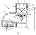
- Figure 1 shows the basic construction of a pressure relief valve unit 10, which comprises an attachment 11 for securing the pressure relief valve 10 to the end of a vent of the storage tank, a positive pressure relief valve 12 and a vacuum relief valve 13.
- the positive pressure relief valve 12 comprises a primary valve element 15 which is generally cylindrical apart from a frusto-conical lower end 16.
- the frusto-conical surface 16 is provided with an annular recess 17 within which an O-ring 18 locates for sealing purposes.
- the primary valve element 15 locates within a seat 19 that is formed in a valve body 14.
- the primary valve element 15 is of a generally cylindrical nature, and the portion 22 of the valve body 14 within which the primary valve element 15 locates is provided with a plurality of ribs 21 which project outwardly from the internal surface of the portion 22. These ribs 21 are evenly spaced circumferentially around the outlet portion 22 of the valve body 14, and are arranged to provide a sliding fit with respect to the primary valve element 15, so as to maintain it centrally located within the outlet portion 22.
- the valve body 14 is cast and, therefore, the ribs 21 would normally extend from the upper portion of the outlet 22 to the edge of the seat 19.
- the primary valve element 15 were to locate on the seat 19, then there may not be sufficient clearance between the ribs 21 and the outer surface of the primary valve element 15 to allow adequate drainage of condensate, which would therefore accumulate between adjacent ribs 21.
- the lower end of each of the ribs 21 is machined back to the internal wall of the outlet portion 22, so as to provide a clear channel for water drainage from around the base of the primary valve element 15. Therefore, it is necessary only to provide one drainage aperture in the valve body 14, which overall results in a reduced number of machining operations.
- the ribs 21 are machined so as to provide a ridge 23 which is an annulus that extends around the circumference of the primary valve element 15. This ridge 23 is angled with respect to the horizontal such that its lowest point is adjacent the drainage aperture. This sloping of the ridge surface 23 encourages rapid drainage through the single drainage aperture.
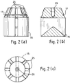
- any condensate locating between the frusto-conical surface 16 and the seat 19 will be drawn into the longitudinal recesses 25. If sufficient longitudinal recesses 25 are provided, then the reservoir afforded by each recess 25 will be sufficient to store a reasonably large amount of condensate. This condensate will primarily be held away from the seat 19, and therefore if freezing occurs, the primary valve element 15 will still be able to operate safely. Even if condensate which gathers within the longitudinal recesses 25 comes into contact with the seat 19, the localised freezing will not result in a significant adherence force around the perimeter of the seat 19, and again the primary valve element 15 will operate satisfactorily.
- the primary valve element 26 of the later described vacuum relief valve 13 may also be provided with longitudinal recesses such as recess 25, which of course operate in the same manner as described above.
- the primary valve element 15 operates to relieve excessive pressure building up within the storage tank. The point at which this pressure relief occurs is dependent upon the weight and cross-sectional surface area of the primary valve element 15. Once a predetermined pressure point is reached, then the primary valve element will be lifted clear of the seat 19, thereby allowing pressure relief. Once the pressure has decreased, then the primary valve element 15 will once again lower and seal against the seat 19.
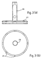
- the primary valve element 26 including bottom plate 27 of the vacuum relief valve 13 will raise, thereby allowing air to enter the storage tank. Again, once the vacuum has been relieved, then the primary valve element 26 will lower and reseal.
- each of the primary valve elements 15 and 26 a low pressure (or vacuum) relief valve 28.
- each such valve 28 comprises a conduit 29 which extends through the primary valve element 26 (or 15), a movable valve element which in this embodiment is a steel ball 30 and a seat 31 which locates within an end of the conduit 29.
- the seat 31 comprises a threaded element which has a relatively small aperture 32 therethrough. This small aperture 32 allows for a minor flow through the low pressure relief valve 28 so as to relieve any minor pressure build up or any minor vacuum that may occur.
- the inside end of the seat 31 has a depression therein within which the steel ball 30 locates for sealing purposes.
- the low pressure relief valve 28 in the primary valve element 15 will operate, whereby the steel ball 30 lifts off the aperture 32, thereby allowing flow at a low rate from within the valve body 14 to atmosphere.
- the low pressure relief valve 28 in the primary valve element 26 will operate, whereby the steel ball 30 lifts, allowing air from atmosphere to flow at low rate into the valve body 14.
- the pressure relief valve 10 is provided with a manual operating arm 34 which can be used manually to raise the primary valve element 15. This manual operation may be used during the filling process of the storage tank so as to maximise air discharge from the storage tank during the filling process.
Landscapes
- Engineering & Computer Science (AREA)
- General Engineering & Computer Science (AREA)
- Mechanical Engineering (AREA)
- Self-Closing Valves And Venting Or Aerating Valves (AREA)
Applications Claiming Priority (2)
| Application Number | Priority Date | Filing Date | Title |
|---|---|---|---|
| AUPL9117/93 | 1993-06-01 | ||
| AUPL911793 | 1993-06-01 |
Publications (1)
| Publication Number | Publication Date |
|---|---|
| EP0629803A1 true EP0629803A1 (fr) | 1994-12-21 |
Family
ID=3776936
Family Applications (1)
| Application Number | Title | Priority Date | Filing Date |
|---|---|---|---|
| EP94303889A Withdrawn EP0629803A1 (fr) | 1993-06-01 | 1994-05-27 | Agencement de soupape de surpression |
Country Status (1)
| Country | Link |
|---|---|
| EP (1) | EP0629803A1 (fr) |
Cited By (1)
| Publication number | Priority date | Publication date | Assignee | Title |
|---|---|---|---|---|
| WO1997018410A1 (fr) * | 1995-11-14 | 1997-05-22 | Vapa-Sava Uk Sales & Distribution Limited | Soupape de confinement de vapeur |
Citations (4)
| Publication number | Priority date | Publication date | Assignee | Title |
|---|---|---|---|---|
| US2093035A (en) * | 1935-12-17 | 1937-09-14 | Holden H Davies | Pressure regulating valve |
| GB634829A (en) * | 1947-12-01 | 1950-03-29 | William Ralph Sergeant | Improvements in or relating to safety valves |
| GB1118856A (en) * | 1965-07-28 | 1968-07-03 | Gen Precision Inc | Floating diaphragm relief valve |
| AU559799B2 (en) * | 1983-06-16 | 1987-03-19 | Broer Enterprises Pty. Ltd. | Pressure vacuum valve |
-
1994
- 1994-05-27 EP EP94303889A patent/EP0629803A1/fr not_active Withdrawn
Patent Citations (4)
| Publication number | Priority date | Publication date | Assignee | Title |
|---|---|---|---|---|
| US2093035A (en) * | 1935-12-17 | 1937-09-14 | Holden H Davies | Pressure regulating valve |
| GB634829A (en) * | 1947-12-01 | 1950-03-29 | William Ralph Sergeant | Improvements in or relating to safety valves |
| GB1118856A (en) * | 1965-07-28 | 1968-07-03 | Gen Precision Inc | Floating diaphragm relief valve |
| AU559799B2 (en) * | 1983-06-16 | 1987-03-19 | Broer Enterprises Pty. Ltd. | Pressure vacuum valve |
Cited By (1)
| Publication number | Priority date | Publication date | Assignee | Title |
|---|---|---|---|---|
| WO1997018410A1 (fr) * | 1995-11-14 | 1997-05-22 | Vapa-Sava Uk Sales & Distribution Limited | Soupape de confinement de vapeur |
Similar Documents
| Publication | Publication Date | Title |
|---|---|---|
| US5755252A (en) | Control valve with two-stage shutoff and peel away opening action | |
| US5322099A (en) | Apparatus for preventing fuel spillage | |
| EP0100657B1 (fr) | Soupape d'admission d'air | |
| US4796777A (en) | Vented fuel tank cap and valve assembly | |
| EP0648318B1 (fr) | Systeme de securite destine a des recipients de fluide sous pression | |
| US2111473A (en) | Combination air discharge and vacuum valve | |
| US4512492A (en) | Manhole closure with a single liquid impervious, two-way gas pressure relief valve | |
| US6056005A (en) | Vent valve with liquid seal | |
| US4674530A (en) | Pressure relief device for vessels | |
| US5435335A (en) | Overflow valve | |
| EP0059558A1 (fr) | Vanne de sous pression pour systèmes sanitaires | |
| US3976096A (en) | Valve | |
| US3064668A (en) | Container vent valve | |
| US3568695A (en) | Fluid pressure relief vacuum relief, and overturn check valve | |
| US6840263B2 (en) | Multifunctional valve for the fuel tank of a motor vehicle | |
| US4266568A (en) | Vacuum breaker-pressure release device | |
| US4342329A (en) | Breather valve | |
| US4274431A (en) | Fuel vent with gravity valve | |
| US4376446A (en) | Vent valve for fuel tanks and the like | |
| US2731030A (en) | Overflow float valves | |
| US8302797B2 (en) | Storage tank floating roof sump with emergency overflow | |
| US3486528A (en) | Vent valve having dynamic valve opening structure | |
| US5603425A (en) | Radiator cap | |
| US3736951A (en) | Mushroom-shaped drain valve and method of using the same | |
| US4222405A (en) | Pressure vacuum breaker |
Legal Events
| Date | Code | Title | Description |
|---|---|---|---|
| PUAI | Public reference made under article 153(3) epc to a published international application that has entered the european phase |
Free format text: ORIGINAL CODE: 0009012 |
|
| AK | Designated contracting states |
Kind code of ref document: A1 Designated state(s): BE CH DE DK ES FR GB GR IE IT LI NL SE |
|
| 17P | Request for examination filed |
Effective date: 19950721 |
|
| 17Q | First examination report despatched |
Effective date: 19951206 |
|
| STAA | Information on the status of an ep patent application or granted ep patent |
Free format text: STATUS: THE APPLICATION IS DEEMED TO BE WITHDRAWN |
|
| 18D | Application deemed to be withdrawn |
Effective date: 19960417 |