EP0629864B1 - Système optoélectrique pour l'acquisition de signaux de présence de tension, et de phase - Google Patents
Système optoélectrique pour l'acquisition de signaux de présence de tension, et de phase Download PDFInfo
- Publication number
- EP0629864B1 EP0629864B1 EP94108432A EP94108432A EP0629864B1 EP 0629864 B1 EP0629864 B1 EP 0629864B1 EP 94108432 A EP94108432 A EP 94108432A EP 94108432 A EP94108432 A EP 94108432A EP 0629864 B1 EP0629864 B1 EP 0629864B1
- Authority
- EP
- European Patent Office
- Prior art keywords
- optical
- conductor
- electro
- operable
- light
- Prior art date
- Legal status (The legal status is an assumption and is not a legal conclusion. Google has not performed a legal analysis and makes no representation as to the accuracy of the status listed.)
- Expired - Lifetime
Links
- 230000005693 optoelectronics Effects 0.000 title description 3
- 239000004020 conductor Substances 0.000 claims description 31
- 230000003287 optical effect Effects 0.000 claims description 28
- 238000004519 manufacturing process Methods 0.000 claims description 3
- 239000003990 capacitor Substances 0.000 claims description 2
- 230000003071 parasitic effect Effects 0.000 claims description 2
- 230000001419 dependent effect Effects 0.000 claims 1
- 230000008054 signal transmission Effects 0.000 claims 1
- 239000013307 optical fiber Substances 0.000 description 10
- 238000009413 insulation Methods 0.000 description 4
- 230000011664 signaling Effects 0.000 description 4
- 206010014405 Electrocution Diseases 0.000 description 3
- 230000005540 biological transmission Effects 0.000 description 3
- 238000012544 monitoring process Methods 0.000 description 3
- 238000001514 detection method Methods 0.000 description 2
- 238000010586 diagram Methods 0.000 description 2
- 238000009826 distribution Methods 0.000 description 2
- 239000011810 insulating material Substances 0.000 description 2
- 239000012212 insulator Substances 0.000 description 2
- 230000006978 adaptation Effects 0.000 description 1
- 238000013459 approach Methods 0.000 description 1
- 230000015556 catabolic process Effects 0.000 description 1
- 238000006243 chemical reaction Methods 0.000 description 1
- 230000000295 complement effect Effects 0.000 description 1
- 230000008878 coupling Effects 0.000 description 1
- 238000010168 coupling process Methods 0.000 description 1
- 238000005859 coupling reaction Methods 0.000 description 1
- 230000006378 damage Effects 0.000 description 1
- 238000010292 electrical insulation Methods 0.000 description 1
- 238000004146 energy storage Methods 0.000 description 1
- 230000007613 environmental effect Effects 0.000 description 1
- 230000036039 immunity Effects 0.000 description 1
- 238000007689 inspection Methods 0.000 description 1
- 239000000463 material Substances 0.000 description 1
- 238000005259 measurement Methods 0.000 description 1
- 238000000034 method Methods 0.000 description 1
- 239000012811 non-conductive material Substances 0.000 description 1
- 238000012797 qualification Methods 0.000 description 1
- 230000001105 regulatory effect Effects 0.000 description 1
- 239000000523 sample Substances 0.000 description 1
Images


Classifications
-
- G—PHYSICS
- G01—MEASURING; TESTING
- G01R—MEASURING ELECTRIC VARIABLES; MEASURING MAGNETIC VARIABLES
- G01R15/00—Details of measuring arrangements of the types provided for in groups G01R17/00 - G01R29/00, G01R33/00 - G01R33/26 or G01R35/00
- G01R15/14—Adaptations providing voltage or current isolation, e.g. for high-voltage or high-current networks
- G01R15/22—Adaptations providing voltage or current isolation, e.g. for high-voltage or high-current networks using light-emitting devices, e.g. LED, optocouplers
Definitions
- the present invention relates in general to systems for the acquisition of signals indicating the presence of a voltage and its phase in medium and high voltage apparatus, and more specifically refers to a system as defined in the preamble of Claim 1.
- the signal necessary for phase determination and for indicating the presence of a voltage is taken off, by means of an electric circuit, via a capacitive shunt applied externally of internally to the insulating support and/or to an insulator through which the conductor passes, or to the terminal of the cable and/or to the female coupling insulator thereof.
- the sinusoidal electric signal provided by the shunt in question which is characterized by a very modest short circuit current value (from a few units to several tens of micro amps) is utilized for:
- An electro-optical circuit with a voltage rectifier and energy storage elements intended to control the operation of a light source such as a LED diode is, for example, disclosed in DE-A-2 746 570.
- gas discharge lamps are also commonly used as light sources as described in DE-U-8 812 279.
- the object of the present invention is that of overcoming the above-mentioned disadvantages, as well as that of obtaining, with low production cost, an improved opto-electronic system for detecting the presence and phase of a voltage in medium and high voltage conductors.
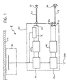
- the system 1 comprises a capacitive shunt DC as mentioned hereinabove and of known type, connected to the single conductor FT of which it is desired to know the presence of voltage or information relating to the phase.
- the nominal operating current range of the shunt DC lies between 2.5 ⁇ A and 35 ⁇ A, however with an adaptation of the electronic circuits it is possible to operate the system 1 with greater currents.
- the system 1 is essentially constituted by an electro-optical convertor EO which has the purpose of converting the electrical signals coming from the capacitive shunt DC into light signals.
- the electro-optical convertor EO comprises a rectifier bridge P1 connected to the capacitive shunt DC.
- the rectifier bridge P1 rectifies the current pulses coming from the capacitive shunt DC.
- the rectifier bridge P1 is connected to an energy accumulator device AC1 which serves to store the modest energy of the pulses coming from the capacitive shunt DC.
- the accumulator device AC1 is typically a capacitive device, that is to say it is formed by capacitors.
- a LED diode L1 Also connected to the accumulator device AC1, in series with the gas discharge lamp SG, is a LED diode L1. Consequently, when the light pulse emitted by the gas discharge lamp SG takes place there is also an emission of a corresponding pulse of light energy from the LED L1.
- an optical fibre F1 in such a way that the emitted pulse of light energy can be transmitted over a distance.
- the optical fibre F1 connected to the LED diode L1 terminates with a lens bulb GL, that is to say an optical device operable to diffuse and render perceptible the light energy transmitted along the optical fibre F1.
- the combination of the optical fibre F1 and the lens bulb GL therefore makes the light pulse emitted from the LED diode L1 visible at a distance. In this way the information relating to the presence of voltage on the conductor FT can be transmitted over a distance of several meters and made visible to a human observer.
- a second rectifier bridge P2 is employed and a second energy accumulator device AC2, which are substantially similar to those described hereinabove.
- the second accumulator device AC2 is also connected to a LED diode L2 operable to emit pulses of light.
- the emission of the light pulses by the LED diode L2 is no longer regulated by the occurrence of a discharge in a gas discharge lamp, but rather by an electronic switch IE.
- the electronic switch IE is connected not only to the accumulator device AC2 and to the LED diode L2, but also directly to the capacitive shunt DC in such a way as to be able to detect, on the basis of the current pulses emitted by the capacitive shunt DC, information relating to the phase.
- the electronic switch IE therefore emits to the LED diode L2 a short pulse in correspondence with each period detected on the conductor FT in the manner explained hereinabove.
- the LED diode L2 is also connected to an optical fibre F2 in a manner similar to that for the LED diode L1.
- the end of the optical fibre F2 is not connected to a lens bulb, but to an optical connector CO in such a way as to be able to carry the information relating to the phase over a distance by means of light impulses.
- phase concordance indicator device In this case, too, the advantage of having an optical conductor is evident in that, in the case of an electrical discharge the human operator who may possibly be connecting the optical fibre F2 to a phase concordance indicator device, does not run any risk of electrocution, nor is there any risk of destruction of the phase concordance indicator device which therefore can be completely free of electrical protection devices. It is obvious that the phase concordance indicator device must be adapted to operate upon the reception of light pulses and must be provided with complementary optical connectors.
- the operation of the system 1 is moreover autonomous and does not require an auxiliary supply for the electronic circuits.
- the board QT naturally includes a section PT containing the high voltage parts. To this section PT is connected a conductor FT. On the conductor FT is situated, as previously mentioned, the capacitive shunt DC to which the electro-optical convertor EO is connected. The electro-optical convertor EO is situated in the rear part RQ of the board QT in such a way that the gas discharge lamp SG is visible through a transparent portion of an inspection panel PAN.
- the optical fibres F1, F2 carry the information to the front part FQ of the board QT.
- On the front part FQ is therefore located the lens bulb GL and the optical connector CO.
- a phase concordance indicator device DISP it is possible to connect a phase concordance indicator device DISP to the connector CO by means of an optical fibre.
- the device DISP is connected to a second board Q2 in such a manner as to detect the phase concordance.
- the present invention can be employed for the detection of information relating to the presence of a voltage and to its phase in overhead conductors.
- An overhead conductor FT can be touched by means of an insulating rod AIS carrying an electro-optical convertor EO according to the invention.
- the electro-optical convertor EO functions thanks to the parasitic capacitance CPAR present between it and ground GND which in practice performs the function of the capacitive shunt.
- the information relating to the presence of the voltage and to its phase is brought close to a human operator without any risk, by means of optical fibres F1, F2.
- the optical fibres F1, F2 terminate, as in the preceding case, with a lens bulb GL and an optical connector CO respectively.
- the insulating rod AIS can be handled without any risk on the part of the operator and does not necessitate complex and expensive safety devices to guarantee insulation since, for the major part of its length, it is made of insulating material.
- the rod AIS moreover makes it possible to monitor in an easy and safe manner the presence of a voltage on overhead conductors FT thus contributing to making the work of service personnel very much safer.
- the system envisages the use of flexible PVC optical fibres of low cost although it is possible to use different materials.
Landscapes
- Physics & Mathematics (AREA)
- General Physics & Mathematics (AREA)
- Measuring Instrument Details And Bridges, And Automatic Balancing Devices (AREA)
- Led Devices (AREA)
Claims (21)
- Système (1) de production et de transmission de signaux indicatifs d'une tension alternative dans un conducteur (FT), comprenant :caractérisé en ce que lesdits moyens de conversion électro-optiques (EO) comprennent en outre des moyens de détection (IE) reliés de manière opérationnelle auxdits moyens de dérivation capacitifs (DC) et destinés à émettre des signaux de synchronisation électriques indicatifs de la phase de ladite tension alternative, lesdits moyens de détection (IE) comprenant un commutateur électronique servant à réguler l'émission d'une impulsion lumineuse de synchronisation de courte durée en rapport avec un angle de phase prédéterminé de ladite tension.des moyens de dérivation capacitifs (DC) reliés de manière opérationnelle audit conducteur (FT) et servant à produire des impulsions électriques en présence d'une tension alternative dans ledit conducteur (FT) ;des moyens de conversion électro-optiques (EO) reliés de manière opérationnelle auxdits moyens de dérivation capacitifs (DC) et servant à produire des impulsions lumineuses à partir desdites impulsions électriques ; etdes moyens de conduction optique (F1, F2) reliés auxdits moyens de conversion électro-optiques (EO) et servant à transporter lesdites impulsions lumineuses sur une certaine distance,
- Système (1) selon la revendication 1, caractérisé en ce que lesdits moyens de conversion électro-optiques (EO) incluent des moyens formant pont de redresseurs (P1) servant à redresser lesdites impulsions électriques avant de produire, à partir de celles-ci, des impulsions lumineuses.
- Système (1) selon la revendication 1 ou la revendication 2, caractérisé en ce que lesdits moyens de conversion électro-optiques (EO) incluent des moyens d'accumulation d'énergie (AC1) servant à stocker l'énergie de plusieurs impulsions électriques.
- Système (1) selon l'une quelconque des revendications 1 à 3, caractérisé en ce que lesdits moyens de conversion électro-optiques (EO) incluent deux émetteurs de lumière (SG, L1, L2).
- Système (1) selon la revendication 4, caractérisé en ce que l'un des émetteurs de lumière, qui sert à indiquer la présence de la tension alternative dans le conducteur (FT), comprend une lampe à décharge dans un gaz (SG).
- Système (1) selon la revendication 5, caractérisé en ce que ledit émetteur de. lumière comprend en outre une diode électroluminescente (L1).
- Système (1) selon la revendication 6, caractérisé en ce que lesdits moyens de conduction optique (F1) sont reliés à ladite diode électroluminescente (L1).
- Système (1) selon la revendication 4, caractérisé en ce que le second émetteur de lumière (L2) est relié auxdits moyens de détection (IE) et en ce que des moyens de conduction optique supplémentaires (F2) sont reliés audit second émetteur de lumière (L2).
- Système (1) selon la revendication 8, caractérisé en ce que ledit second émetteur de lumière est une diode électroluminescente supplémentaire (L2).
- Système (1) selon la revendication 8 ou la revendication 9, pour autant que la revendication 4 dépende de la revendication 3, elle-même dépendante de la revendication 2, caractérisé en ce que lesdits moyens de conversion électro-optiques (EO) comprennent :des moyens formant pont de redresseurs supplémentaires (P2) reliés de manière opérationnelle auxdits moyens de dérivation capacitifs (DC),des moyens d'accumulation d'énergie supplémentaires (AC2) interposés entre lesdits moyens formant pont de redresseurs supplémentaires (P2) et ledit second émetteur de lumière (L2) et reliés de manière opérationnelle auxdits moyens de détection (IE).
- Système (1) selon la revendication 10, caractérisé en ce que ledit commutateur électronique est commandé par lesdites impulsions électriques produites par lesdits moyens de dérivation capacitifs (DC).
- Système (1) selon la revendication 11, caractérisé en ce qu'il inclut une perche électriquement isolante (AIS) qui porte lesdits moyens de conversion électro-optiques (EO) à une première extrémité et dont ladite première extrémité peut être mise en contact avec un conducteur aérien (FT) de manière à mettre à disposition, à proximité d'une seconde extrémité, ladite information relative à la tension et à la phase, et ce, à l'aide desdits moyens de conduction optique et de moyens de conduction optique supplémentaires (F1, F2).
- Système (1) selon la revendication 12, caractérisé en ce que lesdits moyens de dérivation capacitifs (DC) fonctionnent grâce à la capacité parasite (CPAR) présente entre lesdits moyens de conversion électro-optiques (EO) et la terre (GND).
- Système (1) selon l'une quelconque des revendications 10 à 13, caractérisé en ce que lesdits moyens formant pont de redresseurs (P1) et lesdits moyens formant pont de redresseurs supplémentaires (P2) comprennent des ponts de redresseurs faits avec des diodes.
- Système (1) selon l'une quelconque des revendications 10 à 14, caractérisé en ce que lesdits moyens d'accumulation d'énergie (AC1) et lesdits moyens d'accumulation d'énergie supplémentaires (AC2) comprennent des dispositifs d'accumulation de type capacitif.
- Système '(1) selon la revendication 15, caractérisé en ce que lesdits dispositifs d'accumulation capacitifs (AC1, AC2) comprennent des condensateurs.
- Système (1) selon l'une quelconque des revendications précédentes, caractérisé en ce que lesdits moyens de conduction optique (F1) incluent un diffuseur optique (GL) servant à rendre perceptibles lesdites impulsions lumineuses.
- Système (1) selon la revendication 17, caractérisé en ce que ledit diffuseur optique comprend une ampoule à lentille (GL).
- Système (1) selon la revendication 8, caractérisé en ce que lesdits moyens de conduction optique supplémentaires (F2) comprennent des moyens de connexion optique (CO) servant à connecter des appareils externes (DISP).
- Système (1) selon la revendication 8, caractérisé en ce que lesdits moyens de conduction optique et lesdits moyens de conduction optique supplémentaires comprennent des fibres optiques (F1, F2).
- Système (1) selon la revendication 20, caractérisé en ce que lesdites fibres optiques (F1, F2) sont faites de chlorure de polyvinyle.
Applications Claiming Priority (3)
| Application Number | Priority Date | Filing Date | Title |
|---|---|---|---|
| ITTO930388 | 1993-06-02 | ||
| ITTO930388A IT1270414B (it) | 1993-06-02 | 1993-06-02 | Sistema optoelettronico per l'acquisizione di segnali di presenza tensione e fase |
| US08/564,635 US5751143A (en) | 1993-06-02 | 1995-11-29 | Opto-electronic system for the acquisition of signals indicating the presence of a voltage and its phase |
Publications (2)
| Publication Number | Publication Date |
|---|---|
| EP0629864A1 EP0629864A1 (fr) | 1994-12-21 |
| EP0629864B1 true EP0629864B1 (fr) | 2002-04-17 |
Family
ID=26332226
Family Applications (1)
| Application Number | Title | Priority Date | Filing Date |
|---|---|---|---|
| EP94108432A Expired - Lifetime EP0629864B1 (fr) | 1993-06-02 | 1994-06-01 | Système optoélectrique pour l'acquisition de signaux de présence de tension, et de phase |
Country Status (2)
| Country | Link |
|---|---|
| US (1) | US5751143A (fr) |
| EP (1) | EP0629864B1 (fr) |
Families Citing this family (5)
| Publication number | Priority date | Publication date | Assignee | Title |
|---|---|---|---|---|
| ITTO20001142A1 (it) * | 2000-12-07 | 2002-06-07 | Fava Natale | Sistema elettro-opto-elettronico di rilevazione direnzionale dei guasti a terra delle fasi e dei guasti di corto-circuito tra le fasi delle |
| US20100145516A1 (en) * | 2008-12-08 | 2010-06-10 | Illinois Tool Works Inc. | High voltage monitoring system and method for spray coating systems |
| US8791831B2 (en) | 2011-09-23 | 2014-07-29 | Eaton Corporation | System including an indicator responsive to an electret for a power bus |
| US9093867B2 (en) | 2011-09-23 | 2015-07-28 | Eaton Corporation | Power system including an electret for a power bus |
| US9297837B2 (en) * | 2012-05-03 | 2016-03-29 | Institut National D'optique | Optical sensor for non-contact voltage measurement |
Family Cites Families (12)
| Publication number | Priority date | Publication date | Assignee | Title |
|---|---|---|---|---|
| US3312895A (en) * | 1962-10-23 | 1967-04-04 | Westinghouse Electric Corp | Transmission line monitor apparatus utilizing electromagnetic radiation between the line and a remote point |
| US3363174A (en) * | 1963-07-18 | 1968-01-09 | Sigma Instruments Inc | Insulating support for high voltage line conductor, including line coupling means |
| DE1538092B2 (de) * | 1965-07-08 | 1972-06-29 | Siemens AG, 1000 Berlin u. 8000 München | Aus stromwandler und kapazitivem spannungswandler bestehende messgruppe |
| DE2363933C3 (de) * | 1973-12-20 | 1980-09-04 | Siemens Ag, 1000 Berlin Und 8000 Muenchen | Kombinierte Strom- und Spannungsmeßeinrichtung |
| US3943367A (en) * | 1975-06-10 | 1976-03-09 | The United States Of America As Represented By The Secretary Of The Army | High frequency optically coupled differential voltage probe with logarithmic response |
| US3991367A (en) * | 1976-01-20 | 1976-11-09 | The United States Of America As Represented By The Secretary Of The Interior | Detection of potential on high-voltage transmission lines |
| US4070572A (en) * | 1976-12-27 | 1978-01-24 | General Electric Company | Linear signal isolator and calibration circuit for electronic current transformer |
| DE2746570A1 (de) * | 1977-10-17 | 1979-04-26 | Ero Starkstrom Kondensatoren | Schaltungsanordnung zur ueberwachung und/oder anzeige der spannung oder des stroms in einer elektrischen leistungskondensatorbatterie |
| DE2845625A1 (de) * | 1978-10-19 | 1980-04-30 | Siemens Ag | Anordnung zur elektrooptischen spannungsmessung |
| DE8812279U1 (de) * | 1988-09-28 | 1989-02-02 | Siemens AG, 1000 Berlin und 8000 München | Überspannungsdetektor, insbesondere für Pulsladevorrichtungen von Impulslasern |
| US5274324A (en) * | 1989-11-08 | 1993-12-28 | Schweitzer Edmund O Jun | Hot line mountable hotline indicator having liquid crystal display with resettable memory function |
| US5420502A (en) * | 1992-12-21 | 1995-05-30 | Schweitzer, Jr.; Edmund O. | Fault indicator with optically-isolated remote readout circuit |
-
1994
- 1994-06-01 EP EP94108432A patent/EP0629864B1/fr not_active Expired - Lifetime
-
1995
- 1995-11-29 US US08/564,635 patent/US5751143A/en not_active Expired - Lifetime
Also Published As
| Publication number | Publication date |
|---|---|
| EP0629864A1 (fr) | 1994-12-21 |
| US5751143A (en) | 1998-05-12 |
Similar Documents
| Publication | Publication Date | Title |
|---|---|---|
| KR101404102B1 (ko) | 활선 경보장치를 포함하는 배전반 및 이에 이용되는 부스바의 복합 센서 | |
| US5959448A (en) | Optically isolated line voltage sensing circuit | |
| JP5073398B2 (ja) | 高電圧線によって鉄道けん引ユニットに供給される電気エネルギを測定する装置 | |
| US20130214922A1 (en) | Electrical panel safety monitor | |
| AR020006A1 (es) | Una disposicion electrica para pozo petrolero que normalmente opera bajo tierra, que comprende un transformador de energia ubicado en la superficie y un medio bombeador debajo de la superficie, pero que ocasionalmente esta sometido a que un conductor de la misma este puesto a tierra | |
| US6703938B1 (en) | Electrical panel safety monitor | |
| US20130293218A1 (en) | Optical sensor for non-contact voltage measurement | |
| US5751143A (en) | Opto-electronic system for the acquisition of signals indicating the presence of a voltage and its phase | |
| US10128661B2 (en) | Status indicator for power generation systems | |
| KR20130131912A (ko) | 활선 경보장치를 포함하는 배전반 및 이에 이용되는 부스바의 에폭시 애자 | |
| KR100544916B1 (ko) | 고정형 활선 접근 경보시스템 | |
| KR102838872B1 (ko) | 전력전송 선로의 활선상태 표시용 측면발광 광섬유에 의한 활선상태 표시 장치 | |
| US4736197A (en) | Transit system third rail warning signal | |
| KR102650941B1 (ko) | 부스바 지지대 및 이를 포함하는 분배전반 | |
| US4929842A (en) | Electro-optical measuring and transmission device using overload and overvoltage protection circuits | |
| CN110809840B (zh) | 具有电源指示灯的电缆耦合器 | |
| US7167351B2 (en) | Faulted current indicator | |
| EP2156529B1 (fr) | Mesures de tension d'éléments électriquement conducteurs dans des systèmes de commande de processus électriques | |
| EP0067702A2 (fr) | Scalpel à laser comportant un dispositif de sécurité | |
| GB2081535A (en) | Continuity monitoring system | |
| KR101864772B1 (ko) | 전위차를 이용한 배전반 이상 검출용 ir 데이터 송신센서 | |
| CN217689443U (zh) | 一种地下电缆、管线深度走向快速检测装置 | |
| RU224100U1 (ru) | Однополюсный указатель высокого напряжения многофункциональный | |
| CA1292772C (fr) | Dispositif pour surveiller la condition de fonctionnement d'une installation electrique | |
| GB2221763A (en) | Current sensing |
Legal Events
| Date | Code | Title | Description |
|---|---|---|---|
| PUAI | Public reference made under article 153(3) epc to a published international application that has entered the european phase |
Free format text: ORIGINAL CODE: 0009012 |
|
| AK | Designated contracting states |
Kind code of ref document: A1 Designated state(s): DE FR GB |
|
| RAX | Requested extension states of the european patent have changed |
Free format text: SI |
|
| RBV | Designated contracting states (corrected) |
Designated state(s): DE FR GB |
|
| 17P | Request for examination filed |
Effective date: 19950619 |
|
| 17Q | First examination report despatched |
Effective date: 19990608 |
|
| GRAG | Despatch of communication of intention to grant |
Free format text: ORIGINAL CODE: EPIDOS AGRA |
|
| RIC1 | Information provided on ipc code assigned before grant |
Free format text: 7G 01R 15/06 A |
|
| GRAG | Despatch of communication of intention to grant |
Free format text: ORIGINAL CODE: EPIDOS AGRA |
|
| GRAG | Despatch of communication of intention to grant |
Free format text: ORIGINAL CODE: EPIDOS AGRA |
|
| GRAH | Despatch of communication of intention to grant a patent |
Free format text: ORIGINAL CODE: EPIDOS IGRA |
|
| DAX | Request for extension of the european patent (deleted) | ||
| REG | Reference to a national code |
Ref country code: GB Ref legal event code: IF02 |
|
| GRAH | Despatch of communication of intention to grant a patent |
Free format text: ORIGINAL CODE: EPIDOS IGRA |
|
| GRAA | (expected) grant |
Free format text: ORIGINAL CODE: 0009210 |
|
| AK | Designated contracting states |
Kind code of ref document: B1 Designated state(s): DE FR GB |
|
| REF | Corresponds to: |
Ref document number: 69430408 Country of ref document: DE Date of ref document: 20020523 |
|
| ET | Fr: translation filed | ||
| ET | Fr: translation filed | ||
| PLBE | No opposition filed within time limit |
Free format text: ORIGINAL CODE: 0009261 |
|
| STAA | Information on the status of an ep patent application or granted ep patent |
Free format text: STATUS: NO OPPOSITION FILED WITHIN TIME LIMIT |
|
| 26N | No opposition filed |
Effective date: 20030120 |
|
| PGFP | Annual fee paid to national office [announced via postgrant information from national office to epo] |
Ref country code: GB Payment date: 20110620 Year of fee payment: 18 |
|
| PGFP | Annual fee paid to national office [announced via postgrant information from national office to epo] |
Ref country code: FR Payment date: 20110722 Year of fee payment: 18 |
|
| PGFP | Annual fee paid to national office [announced via postgrant information from national office to epo] |
Ref country code: DE Payment date: 20110830 Year of fee payment: 18 |
|
| GBPC | Gb: european patent ceased through non-payment of renewal fee |
Effective date: 20120601 |
|
| REG | Reference to a national code |
Ref country code: FR Ref legal event code: ST Effective date: 20130228 |
|
| REG | Reference to a national code |
Ref country code: DE Ref legal event code: R119 Ref document number: 69430408 Country of ref document: DE Effective date: 20130101 |
|
| PG25 | Lapsed in a contracting state [announced via postgrant information from national office to epo] |
Ref country code: DE Free format text: LAPSE BECAUSE OF NON-PAYMENT OF DUE FEES Effective date: 20130101 Ref country code: GB Free format text: LAPSE BECAUSE OF NON-PAYMENT OF DUE FEES Effective date: 20120601 Ref country code: FR Free format text: LAPSE BECAUSE OF NON-PAYMENT OF DUE FEES Effective date: 20120702 |