EP0629874A1 - Bobine à gradient - Google Patents
Bobine à gradient Download PDFInfo
- Publication number
- EP0629874A1 EP0629874A1 EP94304006A EP94304006A EP0629874A1 EP 0629874 A1 EP0629874 A1 EP 0629874A1 EP 94304006 A EP94304006 A EP 94304006A EP 94304006 A EP94304006 A EP 94304006A EP 0629874 A1 EP0629874 A1 EP 0629874A1
- Authority
- EP
- European Patent Office
- Prior art keywords
- current density
- coil
- width
- magnetic resonance
- windings
- Prior art date
- Legal status (The legal status is an assumption and is not a legal conclusion. Google has not performed a legal analysis and makes no representation as to the accuracy of the status listed.)
- Granted
Links
- 238000004804 winding Methods 0.000 claims abstract description 66
- 238000010276 construction Methods 0.000 claims abstract description 40
- 238000002595 magnetic resonance imaging Methods 0.000 claims abstract description 22
- 239000011888 foil Substances 0.000 claims description 20
- 238000000034 method Methods 0.000 claims description 19
- 239000004020 conductor Substances 0.000 claims description 16
- 239000000463 material Substances 0.000 claims description 5
- 239000000758 substrate Substances 0.000 claims description 4
- 230000001939 inductive effect Effects 0.000 claims description 3
- 238000001208 nuclear magnetic resonance pulse sequence Methods 0.000 claims description 3
- 230000001627 detrimental effect Effects 0.000 abstract 2
- RYGMFSIKBFXOCR-UHFFFAOYSA-N Copper Chemical compound [Cu] RYGMFSIKBFXOCR-UHFFFAOYSA-N 0.000 description 7
- 229910052802 copper Inorganic materials 0.000 description 5
- 239000010949 copper Substances 0.000 description 5
- 238000005520 cutting process Methods 0.000 description 5
- 229910052734 helium Inorganic materials 0.000 description 5
- 239000001307 helium Substances 0.000 description 5
- SWQJXJOGLNCZEY-UHFFFAOYSA-N helium atom Chemical compound [He] SWQJXJOGLNCZEY-UHFFFAOYSA-N 0.000 description 5
- 239000004593 Epoxy Substances 0.000 description 3
- 230000008901 benefit Effects 0.000 description 3
- 230000020169 heat generation Effects 0.000 description 3
- CWYNVVGOOAEACU-UHFFFAOYSA-N Fe2+ Chemical compound [Fe+2] CWYNVVGOOAEACU-UHFFFAOYSA-N 0.000 description 2
- 238000001816 cooling Methods 0.000 description 2
- 239000011889 copper foil Substances 0.000 description 2
- 238000009826 distribution Methods 0.000 description 2
- 230000006870 function Effects 0.000 description 2
- 238000010438 heat treatment Methods 0.000 description 2
- 230000006872 improvement Effects 0.000 description 2
- 238000003754 machining Methods 0.000 description 2
- 230000008569 process Effects 0.000 description 2
- XLYOFNOQVPJJNP-UHFFFAOYSA-N water Substances O XLYOFNOQVPJJNP-UHFFFAOYSA-N 0.000 description 2
- 229920002799 BoPET Polymers 0.000 description 1
- 239000005041 Mylar™ Substances 0.000 description 1
- XAGFODPZIPBFFR-UHFFFAOYSA-N aluminium Chemical compound [Al] XAGFODPZIPBFFR-UHFFFAOYSA-N 0.000 description 1
- 229910052782 aluminium Inorganic materials 0.000 description 1
- 150000001875 compounds Chemical class 0.000 description 1
- 239000012809 cooling fluid Substances 0.000 description 1
- 230000008878 coupling Effects 0.000 description 1
- 238000010168 coupling process Methods 0.000 description 1
- 238000005859 coupling reaction Methods 0.000 description 1
- 239000003989 dielectric material Substances 0.000 description 1
- 230000005684 electric field Effects 0.000 description 1
- 238000005530 etching Methods 0.000 description 1
- 239000011152 fibreglass Substances 0.000 description 1
- 239000007788 liquid Substances 0.000 description 1
- 238000003801 milling Methods 0.000 description 1
- 238000001259 photo etching Methods 0.000 description 1
- 239000004033 plastic Substances 0.000 description 1
- 230000009467 reduction Effects 0.000 description 1
- 238000005057 refrigeration Methods 0.000 description 1
- 230000000717 retained effect Effects 0.000 description 1
- 238000000926 separation method Methods 0.000 description 1
- 229910000679 solder Inorganic materials 0.000 description 1
Images


Classifications
-
- G—PHYSICS
- G01—MEASURING; TESTING
- G01R—MEASURING ELECTRIC VARIABLES; MEASURING MAGNETIC VARIABLES
- G01R33/00—Arrangements or instruments for measuring magnetic variables
- G01R33/20—Arrangements or instruments for measuring magnetic variables involving magnetic resonance
- G01R33/28—Details of apparatus provided for in groups G01R33/44 - G01R33/64
- G01R33/32—Excitation or detection systems, e.g. using radio frequency signals
- G01R33/34—Constructional details, e.g. resonators, specially adapted to MR
-
- G—PHYSICS
- G01—MEASURING; TESTING
- G01R—MEASURING ELECTRIC VARIABLES; MEASURING MAGNETIC VARIABLES
- G01R33/00—Arrangements or instruments for measuring magnetic variables
- G01R33/20—Arrangements or instruments for measuring magnetic variables involving magnetic resonance
- G01R33/28—Details of apparatus provided for in groups G01R33/44 - G01R33/64
- G01R33/38—Systems for generation, homogenisation or stabilisation of the main or gradient magnetic field
- G01R33/385—Systems for generation, homogenisation or stabilisation of the main or gradient magnetic field using gradient magnetic field coils
-
- G—PHYSICS
- G01—MEASURING; TESTING
- G01R—MEASURING ELECTRIC VARIABLES; MEASURING MAGNETIC VARIABLES
- G01R33/00—Arrangements or instruments for measuring magnetic variables
- G01R33/20—Arrangements or instruments for measuring magnetic variables involving magnetic resonance
- G01R33/28—Details of apparatus provided for in groups G01R33/44 - G01R33/64
- G01R33/42—Screening
- G01R33/422—Screening of the radio frequency field
-
- G—PHYSICS
- G01—MEASURING; TESTING
- G01R—MEASURING ELECTRIC VARIABLES; MEASURING MAGNETIC VARIABLES
- G01R33/00—Arrangements or instruments for measuring magnetic variables
- G01R33/20—Arrangements or instruments for measuring magnetic variables involving magnetic resonance
- G01R33/28—Details of apparatus provided for in groups G01R33/44 - G01R33/64
- G01R33/38—Systems for generation, homogenisation or stabilisation of the main or gradient magnetic field
- G01R33/385—Systems for generation, homogenisation or stabilisation of the main or gradient magnetic field using gradient magnetic field coils
- G01R33/3856—Means for cooling the gradient coils or thermal shielding of the gradient coils
-
- G—PHYSICS
- G01—MEASURING; TESTING
- G01R—MEASURING ELECTRIC VARIABLES; MEASURING MAGNETIC VARIABLES
- G01R33/00—Arrangements or instruments for measuring magnetic variables
- G01R33/20—Arrangements or instruments for measuring magnetic variables involving magnetic resonance
- G01R33/28—Details of apparatus provided for in groups G01R33/44 - G01R33/64
- G01R33/42—Screening
- G01R33/421—Screening of main or gradient magnetic field
- G01R33/4215—Screening of main or gradient magnetic field of the gradient magnetic field, e.g. using passive or active shielding of the gradient magnetic field
Definitions
- This invention relates to gradient coils. It finds particular application in conjunction with sheet or "fingerprint" type gradient coil designs for magnetic resonance imaging apparatus and will be described with particular reference thereto. However, it will be appreciated that the present invention will also find application in conjunction with the generation of magnetic fields and gradients for other applications.
- magnetic resonance imagers have included a superconducting magnet which generated a temporally constant primary magnetic field through a central bore.
- a series of annular gradient magnetic field coils for generating x, y, and z-gradient magnetic field gradients were mounted to an interior of the bore.
- An annular radio frequency coil was commonly positioned in the interior of the gradient coils for transmitting radio frequency signals into and receiving radio frequency magnetic resonance signals from a subject in the bore.
- Current pulses were applied to the gradient and radio frequency coils to generate a series of RF and gradient field pulses of conventional magnetic resonance imaging sequences.
- One type of gradient coil includes a flexible, dielectric backing layer to which a sheet of copper or other conductive foil material has been laminated.
- a coil pattern was defined by cutting, milling, or etching the conductive sheet in a generally spiral-like pattern. The conductive sheet remaining between the spiral cut provided a generally spiral or fingerprint-like current path. See, for example, U.S. Patent No. 5,177,442 to Roemer or U.S. Patent No. 4,840,700 to Edelstein.
- the conductive pattern represents an approximation of a continuous current density vector J .
- the contour lines generated by this method determine the machining pattern or cut lines.
- the cut lines were formed by removing a constant width of the conductor material producing an electrical discontinuity or gap which defines the turn pattern.
- the conductive sheet is copper and has a thickness between 1 and 2 mm.
- the cut lines are typically 2 mm. wide, i.e. about equal to the sheet thickness.
- this process of removing a constant width cut line to define the coil pattern results in conductors of varying width.
- the current can spread in the wide areas and becomes concentrated in the narrow conductor areas such that the selected current density J is better met.
- the gradient coil commonly includes a layered assembly of x, y, and z-coils. All three are mounted in very close proximity to one another and are driven in a pulsed manner.
- the resultant magnetic field induces eddy currents in neighboring conductors wherever possible.
- These eddy currents reduce the driving magnetic field and have an associated decay time.
- the neighboring coils are also fingerprint coils, the available current paths for eddy currents have a non-constant spatial distribution.
- the eddy current patterns are spatially dissimilar from the driving field. Both the extended duration of the time decay and the spatial dissimilarity are disadvantageous in magnetic resonance applications.
- the electric field generated by the differences in voltages between adjacent coils results in capacitive coupling. Charging this capacitance also has an associated time constant. It is usually desirable to minimize the time constants and currents associated with this process as well.
- Wire wound gradient coils also have disadvantages.
- the wire width is limited by the minimum contour separation distance and the wire height/thickness is limited by radial build constraints.
- the smallest cross-section is used to wind the entire spiral coil. This results in a coil of higher resistance and higher total heat generation.
- the present invention provides a new and improved gradient coil configuration.
- a gradient coil assembly for causing magnetic field gradients within an examination region.
- the gradient coil assembly includes a plurality of electrically interconnected coil constructions.
- Each of the coil constructions includes an electrically conductive foil sheet which is divided by cut lines into a generally spiral electrically conductive foil winding pattern.
- the foil winding pattern has (1) at least one high current density region in which the windings of the foil winding pattern are narrower than a preselected minimum width and (2) at least one low current density region in which the windings of the foil winding pattern are limited to a preselected maximum width such that gaps are defined between adjacent windings.
- an improvement is provided in a gradient coil assembly which includes a plurality of electrically interconnected coil constructions.
- Each of the coil constructions includes an electrically conductive foil sheet which is divided by cut lines into a generally spiral electrically conductive foil winding pattern.
- the foil winding pattern has at least one high current density region in which the windings of the pattern are narrower than a preselected minimum width.
- the windings in other regions of the pattern are at least the preselected minimum width.
- the improvement comprises defining narrower cut lines in the high current density region than in the other regions of the pattern.
- the wider cut lines can be mechanically milled, cut by abrasive water jet methods or the like.
- a magnetic resonance imaging apparatus In accordance with another aspect of the present invention, a magnetic resonance imaging apparatus is provided.
- a generally toroidal magnet assembly generates a temporally constant magnetic field through an examination region.
- the magnet assembly includes a generally cylindrical member which defines a longitudinally extending bore around the examination region.
- a gradient coil assembly for causing magnetic field gradients within the bore along first, second, and third mutually orthogonal axes is provided.
- the gradient coil assembly includes a first gradient coil having four electrically interconnected coil constructions for causing gradients along one of the mutually orthogonal axes and a second gradient coil including four electrically interconnected coil constructions offset by 90° relative to the first gradient coil for causing magnetic fields along another of the mutually orthogonal axes.
- Each of the coil constructions are essentially as described above.
- a radio frequency coil assembly is disposed within the bore for transmitting radio frequency pulses into the examination region for inducing and manipulating magnetic resonance of selected dipoles.
- a sequence control means controls the gradient coil assembly and the radio frequency coil assembly for generating magnetic resonance imaging gradient and RF pulse sequences.
- An image reconstruction means reconstructs the image representations from magnetic resonance signals emanating from the examination region.
- a method for forming a gradient coil construction from a foil sheet laminated to a dielectric substrate is provided.
- a generally spiral current winding pattern centroid is selected.
- An inter-centroid dimension between adjacent centroids is compared with a first preselected width. In regions in which the inter-centroid dimension is less than the first preselected width, a cut line is defined through the coil, which cut line has a first cut line width. In regions in which the inter-centroid dimension exceeds the first preselected width, a cut line is defined between adjacent centroids, which cut line has a second cut line width. The first cut line width is smaller than the second cut line width.
- another method of forming a gradient coil construction from a foil sheet laminated to a dielectric substrate is provided.
- a generally spiral current winding pattern centroid is selected.
- a dimension between adjacent centroids is compared with a preselected width.
- two cut lines are defined between adjacent centroids. Each cutting line is displaced from a corresponding adjacent centroid by substantially one half the preselected width. In this manner, isolated islands of foil material are defined between adjacent windings.
- the islands are removed or segmented to mitigate intra coil eddy currents.
- One advantage of an apparatus and method embodying the present invention is that it reduces eddy currents in the gradient coils.
- Another advantage of an apparatus and method embodying the present invention is that it improves the distributions of heat generated by the gradient coil. Heating is reduced in regions of high current density and distributed over regions of lower current density.
- Another advantage of an apparatus and method embodying the present invention is that it reduces power loss in the gradient coils.
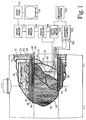
- a plurality of superconducting magnetic field coils 10 generate a generally temporally constant main magnetic field along a longitudinal or z-axis of a central bore 12.
- the x and y-axes are defined orthogonal to the z-axis and each other, e.g. horizontally and vertically.
- Coils of the superconducting magnet are supported by a former 14 and received in a toroidal helium vessel or can 16.
- the helium vessel is filled with liquid helium to maintain the superconducting magnet at a temperature at which it is superconducting.
- a main magnetic field shield coil assembly 18 generates a magnetic field which opposes the field generated by the superconducting magnet 10 in regions surrounding the superconducting magnet.
- the toroidal helium vessel 16 is surrounded by a first cold shield 20 which is maintained at about 20° K. or less.
- a second cold shield assembly 22 is chilled to about 70° K. or less.
- the first and second cold shields are preferably cooled by mechanical refrigeration (not shown).
- the cold shield 22 includes a slotted tube cylindrical cold shield portion which is mounted on a cylindrical dielectric former.
- a toroidal vacuum vessel 24 encases the cold shields to define a vacuum reservoir therearound.
- the vacuum vessel 24 includes a cylindrical, non-ferrous member 26 that defines the bore 12 and extends parallel to the z-axis.
- the main magnetic field is generated through the cylindrical member 26 .
- layers of aluminized (aluminum coated) mylar superinsulation are arranged between the vacuum vessel and the cold shields.
- the RF coil assembly 30 is mounted in the bore.
- the RF coil assembly includes a primary RF coil 32 and an RF shield or secondary coil 34 .
- the primary coil 32 preferably a quadrature or birdcage-type coil, has an inner diameter which defines a patient receiving bore, preferably of at least 55 cm.
- a gradient coil assembly 40 includes a primary whole body gradient coil assembly 42 and a secondary coil assembly 44 .
- the primary gradient coil assembly 42 includes a cylindrical dielectric former 46 .
- the former has a sufficient thickness to maintain its structural integrity under the forces associated with generating the magnetic field gradients, e.g. 5-10 mm of glass reinforced plastic, preferably about 7.5 mm.
- the former 46 has a series of grooves 48 defined or cut in its outer surface to receive the windings of a z-gradient coil 50 .
- the RF shield 34 preferably lapped strips of copper foil or fine copper mesh, is applied to the outer surface of the former 46 and through the z-coil receiving grooves.
- the RF shield mesh may be deformed into the grooves by tightly wound z-gradient wire windings, may be fitted into the grooves, may have solder connected segments extending through the grooves, or the like.
- the grooves have a depth which generally corresponds to the thickness of the z-gradient coils such that after the z-gradient coils are inserted, a substantially circularly cylindrical surface is presented for receiving x and y-gradient coils 52 , 54 .
- the primary z-gradient coil 50 may be either a distributed or bunched coil.
- the coil may be constructed with hollow conductor for circulating a cooling fluid. This would enhance cooling efficiency so as to allow higher power levels or gradient strengths.
- the z-gradient coil need not be next to the RF screen but can be somewhat removed.
- the x and y-gradient coils 52 , 54 each include four windings of the pattern shown in FIGURE 2.
- Two of the constructions are mounted with edges 56 generally adjacent each other and on a vertical center plane 58 of the bore.
- the two constructions wrap about half way around the dielectric former 46 .
- An analogous pair of constructions are mounted on the opposite side of the dielectric former with their edges 56 again adjacent the central vertical plane 58 .
- the constructions wrap around the former such that edges 60 of the oppositely disposed constructions are adjacent each other.
- the x and y-gradient coils are substantially equivalent to each other, but one is rotated 90° around the central or z-axis relative to the other.
- the four coil constructions of one of the gradient coils are mounted to the dielectric former 46 around the RF shield 34 and the z-gradient coil 50 and the assembly potted in epoxy.
- the four coil constructions of the other gradient coil e.g. the y-gradient coil, are mounted around the potted x-gradient coil and also potted in epoxy or other dielectric material.
- the constructions of the outer mounted gradient coil are extended between edges 60 by an appropriate percentage to compensate for the larger diameter about which it is mounted.
- a desired current density J is calculated for each coil construction and a centroid 62 of the current density J is determined.
- the calculated spiral centroid marks the winding pattern which an ideal filament coil would follow.
- Cut lines 64 are defined between adjacent centroids.
- a width 66 of the conductive strip defined between centers of two adjacent cut lines is determined and compared with a preselected minimum width, e.g. 7 mm. and a preselected maximum width, e.g. 12 mm. Where the conductive strips would have a width 66 of less than the preselected minimum, a region 68 of high current density is defined. Where the width 66 between adjacent cut lines would be above the preselected maximum, a region 70 of low current density is defined.
- the coil construction includes a dielectric layer 72 on which a 2 mm. thick film 74 of copper is layered.
- narrow cut lines 76 are defined, preferably by a high pressure water jet cutting operation or other numerically controlled machining operator. In the preferred embodiment, the narrow cut lines 76 are about 1 mm. wide or less.
- the width 66 of the copper foil windings is 6 mm. or less. At this narrow width, 1 mm. cut lines leave a significantly higher percentage of conductive material than would 2 mm. cut lines. In regions in which the width 66 is between 7 and 12 mm., wide cut lines 78 are cut with widths of about 2 mm. Although these regions could also be cut with cut lines of 1 mm., 1 mm. cutting operations can be significantly more expensive than 2 mm. cutting operations.
- the cut line spacing is limited to a preselected width, e.g. 12 mm., center to center. This limits the width of the conductive portion of the coil to 12 mm. less the 2 mm. cut line thickness, i.e. 10 mm.
- the cut lines are positioned such that the width of the conductive coil segment is as close to 12 mm. as possible throughout the coil.
- islands 80 are formed.
- the islands 80 or at least the larger islands, are removed.
- Very small islands which are smaller than the width of the conductors, do not support significant eddy currents and can be retained.
- the larger islands may be cut into smaller pieces to prevent their maintaining large eddy currents.
- a second foil layer 82 may be mounted to the opposite side of the dielectric layer. With two conductive layers, each layer may be half as thick. Hence, any eddy currents induced in the conductors will have a shorter time constant. Moreover, the winding pattern of the two conductive layers need not be the same. Rather, the current density J may be calculated with twice as many, i.e. 2N, loops with alternate loops being defined on each face. Alternate ones of the N loops can be formed on opposing faces allowing each loop to be twice as wide in the high current density region.
- the second conductive layer 82 may be defined only in the region 68 of high current density.
- the cut lines are directly over top of each other, such that analogous conductive strips are formed on both sides of the high current density region.
- Electrical connectors such as copper pins 84 , are drilled through the dielectric layer to interconnect the upper and lower conductive strips.
- the top and bottom conductive strips need not be the same thickness. Rather, the thickness of one or both of the layers can be adjusted such that the combined current carrying capacity of the upper and lower strips matches the current carrying capacity of strips in other regions of the coil construction.
- the use of thinner conductors are advantageous in that they facilitate defining the cut lines by photoetching techniques.
- the thickness of the conductive layer may be adjusted to be thinner in the areas of less current density and thicker in the areas of higher current density.
- additional cut lines can be used to divide these portions into a plurality of parallel conductors connected electrically in parallel.
- a plurality of plastic I-beams or other mechanical structures 90 mount the gradient former 46 to the interior surface of the cylindrical member 26 of the superconducting magnet.
- the I-beams or other mechanical supports 90 define a sufficient gap for receiving main magnet field shims (not shown), typically a multiplicity of ferrous elements, for shimming the uniformity of the main magnetic field.
- main magnet field shims typically a multiplicity of ferrous elements
- an annulus of about 33 mm is provided between the primary gradient coil former 46 and the cylindrical member 26 . This provides passages for air cooling, displaces the primary and shield gradient coils a maximal amount, and provides a compartment within which to insert magnetic field shims for shimming the uniformity of the main magnetic field.
- the secondary gradient coil 44 includes the cylindrical member 26 which preferably has grooves for receiving a z-gradient shield coil 92.
- X and y-gradient shield or secondary coils 94, 96 are mounted on the outer circular periphery of the former 26 and potted in an epoxy compound.
- the primary and secondary gradient coils are connected in series, or independently driven, to create accurate gradient magnetic fields in the bore 12 and cancelling magnetic fields outside the bore, particularly in the vacuum vessel.
- a sequence control means 100 controls a gradient coil control means 102 and a transmitter 104.
- the gradient coil control 102 is connected with a series of current pulse generators 106 which, in turn, are connected with the primary gradient coils 50, 52, 54 and the secondary gradient coils 92, 94, 96.
- the transmitter 104 preferably a digital transmitter, is connected with the primary radio frequency coil for generating pulses of radio frequency signals for exciting and manipulating magnetic resonance in selected dipoles of a portion of a subject within the bore.
- a radio frequency receiver 108 preferably a digital receiver, is connected with the radio frequency primary coil or surface coils (not shown) for demodulating magnetic resonance signals emanating from the examined portion of the subject.
- An image reconstruction means 110 such as an inverse two-dimensional Fourier transform reconstruction means, reconstructs the received magnetic resonance signals into an electronic image representation that is stored in an image memory 112.
- a video processor 114 converts electronic images stored in the memory 112 into appropriate format for display on a video monitor 116.
Landscapes
- Physics & Mathematics (AREA)
- Condensed Matter Physics & Semiconductors (AREA)
- General Physics & Mathematics (AREA)
- Health & Medical Sciences (AREA)
- Epidemiology (AREA)
- Magnetic Resonance Imaging Apparatus (AREA)
Priority Applications (1)
| Application Number | Priority Date | Filing Date | Title |
|---|---|---|---|
| EP00116949A EP1061379B1 (fr) | 1993-06-21 | 1994-06-03 | Bobines à gradient |
Applications Claiming Priority (2)
| Application Number | Priority Date | Filing Date | Title |
|---|---|---|---|
| US80564 | 1993-06-21 | ||
| US08/080,564 US5424643A (en) | 1989-06-16 | 1993-06-21 | Magnetic resonance gradient sheet coils |
Related Child Applications (1)
| Application Number | Title | Priority Date | Filing Date |
|---|---|---|---|
| EP00116949A Division EP1061379B1 (fr) | 1993-06-21 | 1994-06-03 | Bobines à gradient |
Publications (2)
| Publication Number | Publication Date |
|---|---|
| EP0629874A1 true EP0629874A1 (fr) | 1994-12-21 |
| EP0629874B1 EP0629874B1 (fr) | 2001-10-17 |
Family
ID=22158194
Family Applications (2)
| Application Number | Title | Priority Date | Filing Date |
|---|---|---|---|
| EP00116949A Expired - Lifetime EP1061379B1 (fr) | 1993-06-21 | 1994-06-03 | Bobines à gradient |
| EP94304006A Expired - Lifetime EP0629874B1 (fr) | 1993-06-21 | 1994-06-03 | Bobine à gradient |
Family Applications Before (1)
| Application Number | Title | Priority Date | Filing Date |
|---|---|---|---|
| EP00116949A Expired - Lifetime EP1061379B1 (fr) | 1993-06-21 | 1994-06-03 | Bobines à gradient |
Country Status (4)
| Country | Link |
|---|---|
| US (1) | US5424643A (fr) |
| EP (2) | EP1061379B1 (fr) |
| JP (1) | JP3579838B2 (fr) |
| DE (2) | DE69428628T2 (fr) |
Cited By (1)
| Publication number | Priority date | Publication date | Assignee | Title |
|---|---|---|---|---|
| EP2434307A3 (fr) * | 2010-09-22 | 2012-05-23 | Tesla Engineering Limited | Sous-assemblages de bobines de gradient |
Families Citing this family (28)
| Publication number | Priority date | Publication date | Assignee | Title |
|---|---|---|---|---|
| US5554929A (en) * | 1993-03-12 | 1996-09-10 | Doty Scientific, Inc. | Crescent gradient coils |
| JP3140667B2 (ja) * | 1995-08-04 | 2001-03-05 | 三菱電機株式会社 | 磁場発生装置およびその製造方法 |
| US5729141A (en) * | 1996-03-19 | 1998-03-17 | Intermagnetics General Corporation | Split gradient coils for MRI system |
| IT1288452B1 (it) | 1996-11-20 | 1998-09-22 | Esaote Spa | Metodo per migliorare l'efficienza di sistemi di bobine in particolare nei dispositivi di acquisizione di immagini mediante |
| US5804968A (en) * | 1997-01-29 | 1998-09-08 | Picker International, Inc. | Gradient coils with reduced eddy currents |
| US6144204A (en) * | 1997-11-28 | 2000-11-07 | Picker Nordstar Oy | Gradient coils for magnetic resonance meeting |
| US6909283B2 (en) | 2001-04-12 | 2005-06-21 | General Electric Company | Method and system to regulate cooling of a medical imaging device |
| US6516282B2 (en) | 2001-04-19 | 2003-02-04 | Ge Medical Systems Global Technology Company | Predictive thermal control used with a vacuum enclosed coil assembly of a magnetic resonance imaging device |
| JP2003130937A (ja) | 2001-10-24 | 2003-05-08 | Hitachi Ltd | 溶液用核磁気共鳴分析装置 |
| DE10219769B3 (de) * | 2002-05-02 | 2004-01-22 | Siemens Ag | Magnetresonanzgerät und mit Shimelementen bestückbare Trägervorrichtung |
| US6982552B2 (en) * | 2003-05-27 | 2006-01-03 | General Electric Company | Methods and systems for fabricating magnetic resonance gradient coils |
| DE10335790B3 (de) * | 2003-08-05 | 2005-07-28 | Siemens Ag | Erzeuger zeitvariabler Magnetfelder eines Magnetresonanzgeräts und Magnetresonanzgerät mit dem Erzeuger |
| US20050035764A1 (en) * | 2003-08-14 | 2005-02-17 | Anthony Mantone | Method and apparatus for directly cooling hollow conductor wound transverse gradient coil boards |
| US6812705B1 (en) * | 2003-12-05 | 2004-11-02 | General Electric Company | Coolant cooled RF body coil |
| US7782059B2 (en) * | 2004-11-23 | 2010-08-24 | M2M Imaging Corp. | Bandwidth expansion in magnetic resonance |
| DE102006005285A1 (de) * | 2006-02-06 | 2007-08-16 | Siemens Ag | Magnetresonanzeinrichtung sowie Verfahren zur Überwachung einer Magnetresonanzeinrichtung |
| US7271591B1 (en) | 2006-03-15 | 2007-09-18 | General Electric Company | Methods and apparatus for MRI shims |
| JP2007114209A (ja) * | 2006-12-07 | 2007-05-10 | Hitachi Ltd | 溶液用核磁気共鳴分析装置 |
| US7868617B2 (en) | 2007-11-15 | 2011-01-11 | General Electric Co. | Cooling system and apparatus for controlling drift of a main magnetic field in an MRI system |
| JP5352092B2 (ja) * | 2008-02-05 | 2013-11-27 | 株式会社日立メディコ | 傾斜磁場コイル装置および磁気共鳴イメージング装置 |
| US7622927B2 (en) * | 2008-04-11 | 2009-11-24 | Siemens Aktiengesellschaft | Magnetic resonance apparatus with RF amplifier(s) disposed within the spaced distance between the primary and secondary gradient coil windings |
| US8018232B2 (en) | 2009-03-31 | 2011-09-13 | General Electric Company | Interleaved gradient coil for magnetic resonance imaging |
| JP5175892B2 (ja) * | 2009-06-15 | 2013-04-03 | 株式会社東芝 | 超電導磁石装置 |
| US9389291B2 (en) * | 2009-11-27 | 2016-07-12 | Hitachi Medical Corporation | Gradient coil, magnetic resonance imaging device, and method for designing coil pattern |
| CN104411237B (zh) | 2012-06-27 | 2017-05-10 | 株式会社日立制作所 | 倾斜磁场线圈装置及磁共振成像装置 |
| US10295630B2 (en) * | 2015-08-28 | 2019-05-21 | General Electric Company | Gradient coil with variable dimension |
| JP2019508087A (ja) | 2015-12-31 | 2019-03-28 | コーニンクレッカ フィリップス エヌ ヴェKoninklijke Philips N.V. | 最密巻線を有する磁場勾配コイル及びその製造方法 |
| DE102022206592A1 (de) | 2022-06-29 | 2024-01-04 | Siemens Healthcare Gmbh | Gradientenspuleneinheit frei von aktiver Schirmung |
Citations (7)
| Publication number | Priority date | Publication date | Assignee | Title |
|---|---|---|---|---|
| EP0140259A2 (fr) * | 1983-11-02 | 1985-05-08 | General Electric Company | Bobine à champ graduel transversal |
| EP0320285A1 (fr) * | 1987-12-11 | 1989-06-14 | Btg International Limited | Améliorations dans ou rélative aux bobines électriques |
| US4910462A (en) * | 1989-04-28 | 1990-03-20 | General Electric Company | Etched Z-axis gradient coils for NMR system |
| EP0521660A1 (fr) * | 1991-07-01 | 1993-01-07 | General Electric Company | Bobine de gradient transversal pour réaliser une image de la tête |
| JPH0576507A (ja) * | 1991-09-24 | 1993-03-30 | Mitsubishi Electric Corp | 傾斜磁場コイルおよびその製造方法 |
| EP0551517A1 (fr) * | 1990-10-04 | 1993-07-21 | Yokogawa Medical Systems, Ltd | Bobine double generant du champ magnetique a gradient pour l'irm |
| GB2265986A (en) * | 1992-04-08 | 1993-10-13 | Frederick Thomas David Goldie | A folded spiral MRI gradient coil. |
Family Cites Families (12)
| Publication number | Priority date | Publication date | Assignee | Title |
|---|---|---|---|---|
| US4840700A (en) * | 1983-11-02 | 1989-06-20 | General Electric Company | Current streamline method for coil construction |
| US4646024A (en) * | 1983-11-02 | 1987-02-24 | General Electric Company | Transverse gradient field coils for nuclear magnetic resonance imaging |
| US4737716A (en) * | 1986-02-06 | 1988-04-12 | General Electric Company | Self-shielded gradient coils for nuclear magnetic resonance imaging |
| US4733189A (en) * | 1986-06-03 | 1988-03-22 | Massachusetts Institute Of Technology | Magnetic resonance imaging systems |
| US4881035A (en) * | 1987-11-24 | 1989-11-14 | Siemens Aktiengesellschaft | Magnetic structural arrangement of an installation for nuclear magnetic resonance tomography with superconducting background field coils and normal-conducting gradient coils |
| US4794338A (en) * | 1987-11-25 | 1988-12-27 | General Electric Company | Balanced self-shielded gradient coils |
| US4924198A (en) * | 1988-07-05 | 1990-05-08 | General Electric Company | Superconductive magnetic resonance magnet without cryogens |
| US4902995A (en) * | 1988-07-05 | 1990-02-20 | General Electric Company | Cable suspension system for cylindrical cryogenic vessels |
| US4935714A (en) * | 1988-07-05 | 1990-06-19 | General Electric Company | Low thermal conductance support for a radiation shield in a MR magnet |
| US4926125A (en) * | 1988-08-22 | 1990-05-15 | General Electric Company | Surface gradient assembly for high speed nuclear magnetic resonance imaging |
| US5036282A (en) * | 1989-06-16 | 1991-07-30 | Picker International, Inc. | Biplanar gradient coil for magnetic resonance imaging systems |
| US5177441A (en) * | 1989-06-16 | 1993-01-05 | Picker International, Inc. | Elliptical cross section gradient oil |
-
1993
- 1993-06-21 US US08/080,564 patent/US5424643A/en not_active Expired - Lifetime
-
1994
- 1994-06-03 DE DE69428628T patent/DE69428628T2/de not_active Expired - Fee Related
- 1994-06-03 EP EP00116949A patent/EP1061379B1/fr not_active Expired - Lifetime
- 1994-06-03 DE DE69431933T patent/DE69431933T2/de not_active Expired - Fee Related
- 1994-06-03 EP EP94304006A patent/EP0629874B1/fr not_active Expired - Lifetime
- 1994-06-17 JP JP15940594A patent/JP3579838B2/ja not_active Expired - Fee Related
Patent Citations (7)
| Publication number | Priority date | Publication date | Assignee | Title |
|---|---|---|---|---|
| EP0140259A2 (fr) * | 1983-11-02 | 1985-05-08 | General Electric Company | Bobine à champ graduel transversal |
| EP0320285A1 (fr) * | 1987-12-11 | 1989-06-14 | Btg International Limited | Améliorations dans ou rélative aux bobines électriques |
| US4910462A (en) * | 1989-04-28 | 1990-03-20 | General Electric Company | Etched Z-axis gradient coils for NMR system |
| EP0551517A1 (fr) * | 1990-10-04 | 1993-07-21 | Yokogawa Medical Systems, Ltd | Bobine double generant du champ magnetique a gradient pour l'irm |
| EP0521660A1 (fr) * | 1991-07-01 | 1993-01-07 | General Electric Company | Bobine de gradient transversal pour réaliser une image de la tête |
| JPH0576507A (ja) * | 1991-09-24 | 1993-03-30 | Mitsubishi Electric Corp | 傾斜磁場コイルおよびその製造方法 |
| GB2265986A (en) * | 1992-04-08 | 1993-10-13 | Frederick Thomas David Goldie | A folded spiral MRI gradient coil. |
Non-Patent Citations (1)
| Title |
|---|
| PATENT ABSTRACTS OF JAPAN vol. 17, no. 400 (C - 1089)<6029> 27 July 1993 (1993-07-27) * |
Cited By (3)
| Publication number | Priority date | Publication date | Assignee | Title |
|---|---|---|---|---|
| EP2434307A3 (fr) * | 2010-09-22 | 2012-05-23 | Tesla Engineering Limited | Sous-assemblages de bobines de gradient |
| US8674692B2 (en) | 2010-09-22 | 2014-03-18 | Tesla Engineering Limited | Gradient coil sub-assemblies |
| US10031194B2 (en) | 2010-09-22 | 2018-07-24 | Tesla Engineering Limited | Gradient coil sub-assemblies |
Also Published As
| Publication number | Publication date |
|---|---|
| DE69431933T2 (de) | 2003-08-28 |
| DE69431933D1 (de) | 2003-01-30 |
| US5424643A (en) | 1995-06-13 |
| JP3579838B2 (ja) | 2004-10-20 |
| EP0629874B1 (fr) | 2001-10-17 |
| EP1061379B1 (fr) | 2002-12-18 |
| DE69428628T2 (de) | 2002-05-08 |
| DE69428628D1 (de) | 2001-11-22 |
| JPH07303624A (ja) | 1995-11-21 |
| EP1061379A2 (fr) | 2000-12-20 |
| EP1061379A3 (fr) | 2001-01-24 |
Similar Documents
| Publication | Publication Date | Title |
|---|---|---|
| EP0629874B1 (fr) | Bobine à gradient | |
| EP0629873B1 (fr) | Combinaison de bobines de gradients auto-blindées avec ensemble d'équilibrage | |
| US5280247A (en) | Filamentary cold shield for superconducting magnets | |
| EP0629875B1 (fr) | Bobine à gradient pour résonance magnétique et écran magnétique haute fréquence | |
| JP3451558B2 (ja) | 磁気共鳴撮像システム | |
| US5036282A (en) | Biplanar gradient coil for magnetic resonance imaging systems | |
| US4733189A (en) | Magnetic resonance imaging systems | |
| US5278504A (en) | Gradient coil with off center sweet spot for magnetic resonance imaging | |
| EP0562708B1 (fr) | Systèmes d'aimants superconducteurs | |
| US7777489B2 (en) | Magnetic resonance imaging apparatus, shield coil, manufacturing method of shield coil, and driving method of magnetic resonance imaging apparatus | |
| US5592087A (en) | Low eddy current radio frequency shield for magnetic resonance imaging | |
| EP1281092B1 (fr) | Appareil de resonance magnetique comprenant une structure guidant le flux magnetique rf | |
| US5414399A (en) | Open access superconducting MRI magnet having an apparatus for reducing magnetic hysteresis in superconducting MRI systems | |
| US5177441A (en) | Elliptical cross section gradient oil | |
| US6278276B1 (en) | Phased array gradient coil set with an off center gradient field sweet spot | |
| US5804968A (en) | Gradient coils with reduced eddy currents | |
| GB2323207A (en) | Flexible hollow electrical cable |
Legal Events
| Date | Code | Title | Description |
|---|---|---|---|
| PUAI | Public reference made under article 153(3) epc to a published international application that has entered the european phase |
Free format text: ORIGINAL CODE: 0009012 |
|
| AK | Designated contracting states |
Kind code of ref document: A1 Designated state(s): DE FR NL |
|
| 17P | Request for examination filed |
Effective date: 19950613 |
|
| 17Q | First examination report despatched |
Effective date: 19991103 |
|
| GRAG | Despatch of communication of intention to grant |
Free format text: ORIGINAL CODE: EPIDOS AGRA |
|
| GRAG | Despatch of communication of intention to grant |
Free format text: ORIGINAL CODE: EPIDOS AGRA |
|
| GRAH | Despatch of communication of intention to grant a patent |
Free format text: ORIGINAL CODE: EPIDOS IGRA |
|
| RAP1 | Party data changed (applicant data changed or rights of an application transferred) |
Owner name: MARCONI MEDICAL SYSTEMS, INC. |
|
| GRAH | Despatch of communication of intention to grant a patent |
Free format text: ORIGINAL CODE: EPIDOS IGRA |
|
| GRAA | (expected) grant |
Free format text: ORIGINAL CODE: 0009210 |
|
| AK | Designated contracting states |
Kind code of ref document: B1 Designated state(s): DE FR NL |
|
| REF | Corresponds to: |
Ref document number: 69428628 Country of ref document: DE Date of ref document: 20011122 |
|
| ET | Fr: translation filed | ||
| PLBE | No opposition filed within time limit |
Free format text: ORIGINAL CODE: 0009261 |
|
| STAA | Information on the status of an ep patent application or granted ep patent |
Free format text: STATUS: NO OPPOSITION FILED WITHIN TIME LIMIT |
|
| 26N | No opposition filed | ||
| PGFP | Annual fee paid to national office [announced via postgrant information from national office to epo] |
Ref country code: NL Payment date: 20030513 Year of fee payment: 10 |
|
| REG | Reference to a national code |
Ref country code: FR Ref legal event code: CD |
|
| REG | Reference to a national code |
Ref country code: FR Ref legal event code: TP |
|
| PG25 | Lapsed in a contracting state [announced via postgrant information from national office to epo] |
Ref country code: NL Free format text: LAPSE BECAUSE OF NON-PAYMENT OF DUE FEES Effective date: 20050101 |
|
| NLV4 | Nl: lapsed or anulled due to non-payment of the annual fee |
Effective date: 20050101 |
|
| PGFP | Annual fee paid to national office [announced via postgrant information from national office to epo] |
Ref country code: DE Payment date: 20080808 Year of fee payment: 15 |
|
| PGFP | Annual fee paid to national office [announced via postgrant information from national office to epo] |
Ref country code: FR Payment date: 20090626 Year of fee payment: 16 |
|
| PG25 | Lapsed in a contracting state [announced via postgrant information from national office to epo] |
Ref country code: DE Free format text: LAPSE BECAUSE OF NON-PAYMENT OF DUE FEES Effective date: 20100101 |
|
| REG | Reference to a national code |
Ref country code: FR Ref legal event code: ST Effective date: 20110228 |
|
| PG25 | Lapsed in a contracting state [announced via postgrant information from national office to epo] |
Ref country code: FR Free format text: LAPSE BECAUSE OF NON-PAYMENT OF DUE FEES Effective date: 20100630 |