EP0629902A1 - Procédé et dispositif d'alimentation en film continu - Google Patents
Procédé et dispositif d'alimentation en film continu Download PDFInfo
- Publication number
- EP0629902A1 EP0629902A1 EP94108953A EP94108953A EP0629902A1 EP 0629902 A1 EP0629902 A1 EP 0629902A1 EP 94108953 A EP94108953 A EP 94108953A EP 94108953 A EP94108953 A EP 94108953A EP 0629902 A1 EP0629902 A1 EP 0629902A1
- Authority
- EP
- European Patent Office
- Prior art keywords
- film
- films
- case
- roller
- core
- Prior art date
- Legal status (The legal status is an assumption and is not a legal conclusion. Google has not performed a legal analysis and makes no representation as to the accuracy of the status listed.)
- Granted
Links
Images





Classifications
-
- G—PHYSICS
- G03—PHOTOGRAPHY; CINEMATOGRAPHY; ANALOGOUS TECHNIQUES USING WAVES OTHER THAN OPTICAL WAVES; ELECTROGRAPHY; HOLOGRAPHY
- G03D—APPARATUS FOR PROCESSING EXPOSED PHOTOGRAPHIC MATERIALS; ACCESSORIES THEREFOR
- G03D3/00—Liquid processing apparatus involving immersion; Washing apparatus involving immersion
- G03D3/08—Liquid processing apparatus involving immersion; Washing apparatus involving immersion having progressive mechanical movement of exposed material
-
- B—PERFORMING OPERATIONS; TRANSPORTING
- B65—CONVEYING; PACKING; STORING; HANDLING THIN OR FILAMENTARY MATERIAL
- B65H—HANDLING THIN OR FILAMENTARY MATERIAL, e.g. SHEETS, WEBS, CABLES
- B65H29/00—Delivering or advancing articles from machines; Advancing articles to or into piles
- B65H29/006—Winding articles into rolls
-
- B—PERFORMING OPERATIONS; TRANSPORTING
- B65—CONVEYING; PACKING; STORING; HANDLING THIN OR FILAMENTARY MATERIAL
- B65H—HANDLING THIN OR FILAMENTARY MATERIAL, e.g. SHEETS, WEBS, CABLES
- B65H5/00—Feeding articles separated from piles; Feeding articles to machines
- B65H5/28—Feeding articles stored in rolled or folded bands
-
- G—PHYSICS
- G03—PHOTOGRAPHY; CINEMATOGRAPHY; ANALOGOUS TECHNIQUES USING WAVES OTHER THAN OPTICAL WAVES; ELECTROGRAPHY; HOLOGRAPHY
- G03B—APPARATUS OR ARRANGEMENTS FOR TAKING PHOTOGRAPHS OR FOR PROJECTING OR VIEWING THEM; APPARATUS OR ARRANGEMENTS EMPLOYING ANALOGOUS TECHNIQUES USING WAVES OTHER THAN OPTICAL WAVES; ACCESSORIES THEREFOR
- G03B27/00—Photographic printing apparatus
- G03B27/32—Projection printing apparatus, e.g. enlarger, copying camera
- G03B27/46—Projection printing apparatus, e.g. enlarger, copying camera for automatic sequential copying of different originals, e.g. enlargers, roll film printers
-
- G—PHYSICS
- G03—PHOTOGRAPHY; CINEMATOGRAPHY; ANALOGOUS TECHNIQUES USING WAVES OTHER THAN OPTICAL WAVES; ELECTROGRAPHY; HOLOGRAPHY
- G03B—APPARATUS OR ARRANGEMENTS FOR TAKING PHOTOGRAPHS OR FOR PROJECTING OR VIEWING THEM; APPARATUS OR ARRANGEMENTS EMPLOYING ANALOGOUS TECHNIQUES USING WAVES OTHER THAN OPTICAL WAVES; ACCESSORIES THEREFOR
- G03B27/00—Photographic printing apparatus
- G03B27/32—Projection printing apparatus, e.g. enlarger, copying camera
- G03B27/52—Details
- G03B27/58—Baseboards, masking frames, or other holders for the sensitive material
- G03B27/587—Handling photosensitive webs
- G03B27/588—Supply rolls; Cutting arrangements
Definitions
- This invention relates to a continuous film feed device for continuously feeding films to a photographic printing apparatus and a method therefor.
- this device since this device is provided with no means for holding in position the leading end of the first one of the films thus wound, the leading end may retract in the feed device when detaching the film feed device from the photographic printing apparatus. Thus, when mounting this device on a photographic printing apparatus, the film leading end has to be pulled out of the case through its outlet. This work is troublesome and can damage the film leading end.
- a method of continuously feeding films comprising the steps of winding a plurality of films one after another around a film core rotatably supported in a case, with the ends of the adjacent films overlapped by putting the leading end of each film under the tail end of the preceding film wound immediately before the each film, and feeding the films continuously by pulling out each film by use of overlapped portions.
- films are preferably wound around the core with their ends overlapped while pressing them toward the center of the core with rollers.
- a continuous film feeding device comprising a case having a lid which can be opened, a film core rotatably supported in the case, a film presser means provided around the film core and comprising rollers for pressing against the film core the films wound around the film core with the leading end of each film slid under the tail end of the preceding film, the case being formed with an outlet through which the films are pulled out, a feed roller provided outside the case near the outlet, and a mating roller provided inside the case and opposite to the feed roller for feeding the films in cooperation with the feed roller.
- this device is preferably designed such that the mating roller has a shaft urged by an elastic member so as to be movable, wherein an opening for receiving the feed roller is formed near the mating roller, and wherein the inner surface of the lid at a portion between the feed roller and the mating roller is formed as a presser for pressing the films fed therebetween.
- films are wound around the core with their ends overlapped without splicing them together.
- the films thus wound are fed continuously.
- the leading end of each film is slid under the tail end of the preceding film. Since the overlapped portions thus formed are pressed by rollers at all times, they can be fed continuously without the need of splicing their ends.
- the films are pressed by rollers toward the center of the core while being wound, they are reliably wound around the core.
- the feeding device has a feed roller and a mating roller provided opposite to each other. Films are fed continuously by these rollers.
- the mating roller is supported by an elastic member so that its axis is movable, an opening for receiving the feed roller is formed near the mating roller, and the inner surface of the lid at a portion between the feed roller and the mating roller is formed as a presser for pressing films.
- Fig. 1 is an outer perspective view showing the inner structure of a continuous film feed device in one embodiment.
- the side cover is removed to show the inner structure of the device.
- This continuous film feed device 1 comprises a case 2, a film take-up core 3 rotatably mounted in the case 2, and a plurality (four in the embodiment) of roller support arms 5 each having a film presser roller 4 for pressing the film toward the center of the core 3.
- the film take-up core 3 is supported on a rotary shaft 6.
- Numeral 7 designates a lid of the case 2.
- Fig. 2 shows a side view of the continuous film feed device. Shown in Figs. 3A and 3B are sectional views taken along lines A-A and B-B of Fig. 2, respectively.
- roller support arms 5 are supported on respective support shafts 8 and biased by springs (not shown) so that their tips are urged lightly toward the center of the film take-up core 3 to press the film toward its center at all times.
- the springs may be coil springs provided around the support shafts 8 or leaf springs having a suitable shape and provided along the respective roller support arms 5.
- a pair of rollers comprising a feed roller 10 for feeding a film which is provided outside the case 2 and a mating roller 11 provided inside the case 2.
- Film is fed out through a film outlet 12 formed in one end of the case 2.
- the feed roller 10 is a one-way roller. If the film being fed is pulled with a torque higher than a predetermined value, the feed roller 10 will go idle. When the pulling force disappears, the film is fed by the feed roller 10.
- a film guide 13 In front of the film outlet 12 is provided a film guide 13 through which the film is fed in a desired direction.
- the feed roller 10 as the driving roller for film has its shaft 10a connected to and driven by a driving source such as a motor.
- the lid 7 is hinged to the case at its right end and can be opened and closed manually.
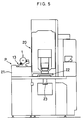
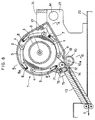
- the continuous film feed device 1 of this embodiment is used as follows: As shown in Figs. 5 and 6, the continuous film feed device 1 is mounted on a photographic printing apparatus 20 near its film infeed portion P, together with the film guide 13 or with the film guide 13 coupled to the device 1 beforehand. Numerals 22 and 23 designate an automatic negative mask and a mirror tunnel, respectively.
- a carrier device 30 comprising a plurality of rollers as shown in Fig. 6. Films f fed from the continuous film feed device 1 are sent to the printing/exposure stage X by the carrier device 30 for printing and exposure. But since this portion is not directly related to the present invention, its detailed description is omitted.
- numeral 41 is a light source; 42 is a light-adjusting filter; 43 is a mirror tunnel; and 44 is a negative mask.
- a plurality of (e.g. 5-10) films f are wound onto the film feed device 1 with their ends (where there are no picture frames) overlapped as shown in Fig. 4. Since films are extremely thin, the diameter of the roll of films will not increase so much even when they are wound with their ends overlapped.
- the overlapped portions are formed by sliding the leading end of each film under the end of the last wound film. Since the overlapped portions are always pressed by the film presser rollers 4, the films are fed continuously.
- the leading end of the topmost film is set between the feed roller 10 and its mating roller 11 beforehand. In this state, by driving the feed roller 10 through its rotary shaft 10a, the films are fed.
- each film When each film is fed into the photographic printing apparatus 20, it is pulled in at high speed by a high-speed roller 30 (Fig. 6) provided near the inlet of the photographic printing apparatus. Thereafter, the feed roller 10 in the continuous film feed device will idle. When the overlapped portion of the films moves past the feed roller 10, the pressure on the overlapped portion is released. The film is thus separated from the subsequent films.
- each film is thus fed into the photographic printing apparatus 20.
- the feed roller 10 is reactivated to feed the next film into it.
- Fig. 7 is a perspective view of the continuous film feed device of another embodiment
- Fig. 8 is its sectional view.
- this embodiment is the same in structure as the first embodiment but differs therefrom mainly in its outer shape, in that it can be mounted on a mounting base and that it is provided with a film end presser mechanism that utilizes the lid of the case.
- the same elements as those in the first embodiment are denoted by the same numerals.
- the case 2 has a semicircular outer configuration.
- a mounting base 21 is provided on the top surface of the case of the photographic printing apparatus 20.
- the case 2 of the continuous film feed device 1 is detachably and obliquely mounted on the mounting base 21 together with the film guide 13.
- the mounting base 21 is a substantially triangular, vertical plate as shown.
- the case 2 is mounted on the front side of the vertical plate, while a driving motor M for driving the feed roller 10 is mounted on the opposite side.
- a mounting seat 15 is provided at the end of the film guide 13, while another mounting seat 24 is provided on top of the mounting base 21.
- Mounting seats 15 and 24 have recesses in which are received mounting pins 16 and 17 that support the case 2. Though not shown, means are provided for preventing the mounting pins 16, 17 from coming out.
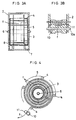
- Figs. 9A and 9B show sectional views taken along lines A-A and B-B of Fig. 8, respectively.
- Feed rollers 10 are mounted in a cantilever fashion through its rotary shaft 10a extending through the mounting base 21.
- a timing belt 10b is put around the rotary shaft 10a at its other end.
- the timing belt 10b is also in engagement with the driving motor M shown in Fig. 8.
- Fig. 10 corresponds to Fig. 4 and illustrates how the films are fed.
- films are wound with their ends overlapped without splicing as with the first embodiment. Namely, the leading end of each film is slid under the tail end of the preceding film.
- the length of overlapping portion between the adjacent films has to be longer than the distance between the film presser roller 4 and the feed roller 10.
- the film take-up core 3 has a film leading end presser member 3a whereby the trailing end of the first or innermost film can be reliably fastened to the core 3.
- Presser member 3a is made of a spring material. When all the films are unrolled completely, its tip will spring up slightly from the surface of the core 3. A new film is inserted into the space between the presser member 3a and the core 3 and wound around the core.
- Fig. 11A is a partial enlarged view showing one feed roller 10 and its vicinity.
- Fig. 11B is a sectional view taken along line B-B of Fig. 11A.
- feed rollers 10 are provided at both ends of a drum 10' and larger in diameter than the drum.
- the lid 7 is formed with openings 18 that are wide enough to receive rollers 10.
- the other portion of the lid 7 protrudes inwardly from the inner surface of the lid 7 as a film presser 19.
- Mating rollers 11 are mounted on a rotary shaft which carries at its protruding ends spring bearings 11a which are resiliently supported by coil springs 11b provided at both sides of the case 2.
- Figs. 12A and 12B show the state in which the continuous film feed device 1 is detached and the film leading end is pulled in to the area near the film outlet 12 of the case 2.
Landscapes
- Engineering & Computer Science (AREA)
- Mechanical Engineering (AREA)
- Physics & Mathematics (AREA)
- General Physics & Mathematics (AREA)
- Unwinding Webs (AREA)
- Projection-Type Copiers In General (AREA)
- Replacement Of Web Rolls (AREA)
- Electrodes Of Semiconductors (AREA)
- Junction Field-Effect Transistors (AREA)
Applications Claiming Priority (4)
| Application Number | Priority Date | Filing Date | Title |
|---|---|---|---|
| JP143690/93 | 1993-06-15 | ||
| JP14369093 | 1993-06-15 | ||
| JP6056894A JPH07273129A (ja) | 1993-06-15 | 1994-03-28 | ショットキーゲート型電界効果トランジスタおよびその製造方法 |
| JP60568/94 | 1994-03-30 |
Publications (2)
| Publication Number | Publication Date |
|---|---|
| EP0629902A1 true EP0629902A1 (fr) | 1994-12-21 |
| EP0629902B1 EP0629902B1 (fr) | 1998-04-08 |
Family
ID=26397890
Family Applications (1)
| Application Number | Title | Priority Date | Filing Date |
|---|---|---|---|
| EP94108953A Expired - Lifetime EP0629902B1 (fr) | 1993-06-15 | 1994-06-10 | Procédé et dispositif d'alimentation en film continu |
Country Status (7)
| Country | Link |
|---|---|
| US (1) | US5797560A (fr) |
| EP (1) | EP0629902B1 (fr) |
| JP (1) | JPH07273129A (fr) |
| KR (1) | KR0169525B1 (fr) |
| CN (1) | CN1034369C (fr) |
| CA (1) | CA2125729C (fr) |
| DE (1) | DE69409435T2 (fr) |
Families Citing this family (6)
| Publication number | Priority date | Publication date | Assignee | Title |
|---|---|---|---|---|
| USD445779S1 (en) | 2000-04-14 | 2001-07-31 | Applied Materials, Inc. | Cassette loading device |
| JP3915993B2 (ja) * | 2004-06-16 | 2007-05-16 | ノーリツ鋼機株式会社 | ペーパーマガジン |
| US20080304947A1 (en) * | 2007-06-11 | 2008-12-11 | Stout Kenneth A | Cleanout system for a reciprocating slat conveyor |
| JP6025295B2 (ja) * | 2010-06-24 | 2016-11-16 | 富士通株式会社 | 化合物半導体装置 |
| JP5704027B2 (ja) * | 2011-09-13 | 2015-04-22 | 沖電気工業株式会社 | 媒体処理装置及び媒体取引装置 |
| CN107642530A (zh) * | 2016-07-22 | 2018-01-30 | 福特环球技术公司 | 向部件施加胶条的设备及其总成 |
Citations (4)
| Publication number | Priority date | Publication date | Assignee | Title |
|---|---|---|---|---|
| DE3206251A1 (de) * | 1982-02-20 | 1983-09-08 | C. Keller GmbH u. Co KG, 4530 Ibbenbüren | Einrichtung zum aufwickeln von furnieren auf eine haspel |
| US4411725A (en) * | 1977-10-05 | 1983-10-25 | Cx Corporation | Daylight film splicer |
| US4798375A (en) * | 1986-06-16 | 1989-01-17 | Noritsu Kenkyu Center Co., Ltd. | Device for feeding photosensitive material |
| EP0357355A2 (fr) * | 1988-08-31 | 1990-03-07 | Sony Corporation | Appareil photographique |
Family Cites Families (10)
| Publication number | Priority date | Publication date | Assignee | Title |
|---|---|---|---|---|
| US1138483A (en) * | 1914-01-29 | 1915-05-04 | Robert Johnston | Reel. |
| US1761592A (en) * | 1929-05-18 | 1930-06-03 | Seidel Morris | Pipe-cleaning or cable-laying device |
| US1825782A (en) * | 1930-01-23 | 1931-10-06 | Duff Robert Pender | Device for delivering squares or otherwise shaped pieces of cloth or other sheet material |
| US4107508A (en) * | 1976-06-09 | 1978-08-15 | L'air Liquide, Societe Anonyme Pour L'etude Et L'exploitation Des Procedes Georges Claude | Method and apparatus for welding using fillet-wire |
| US4218135A (en) * | 1977-06-24 | 1980-08-19 | Olympus Optical Co., Ltd. | Roll sheet cassette loading apparatus |
| US4103841A (en) * | 1977-08-26 | 1978-08-01 | Super Products Corporation | Hose reel apparatus |
| JPH0330365Y2 (fr) * | 1986-02-18 | 1991-06-27 | ||
| US4847635A (en) * | 1987-08-13 | 1989-07-11 | Am International, Inc. | Large copy sheet feeding system |
| US4928897A (en) * | 1988-01-18 | 1990-05-29 | Fuji Photo Film Co., Ltd. | Feeder for feeding photosensitive material |
| CA2090776C (fr) * | 1992-05-28 | 1999-10-12 | Scott J. Collins | Distributeur de produit en feuille a plus d'un rouleau |
-
1994
- 1994-03-28 JP JP6056894A patent/JPH07273129A/ja active Pending
- 1994-06-10 EP EP94108953A patent/EP0629902B1/fr not_active Expired - Lifetime
- 1994-06-10 DE DE69409435T patent/DE69409435T2/de not_active Expired - Fee Related
- 1994-06-13 CA CA002125729A patent/CA2125729C/fr not_active Expired - Fee Related
- 1994-06-13 KR KR1019940013246A patent/KR0169525B1/ko not_active Expired - Fee Related
- 1994-06-14 CN CN94108877A patent/CN1034369C/zh not_active Expired - Fee Related
-
1996
- 1996-07-31 US US08/688,969 patent/US5797560A/en not_active Expired - Lifetime
Patent Citations (4)
| Publication number | Priority date | Publication date | Assignee | Title |
|---|---|---|---|---|
| US4411725A (en) * | 1977-10-05 | 1983-10-25 | Cx Corporation | Daylight film splicer |
| DE3206251A1 (de) * | 1982-02-20 | 1983-09-08 | C. Keller GmbH u. Co KG, 4530 Ibbenbüren | Einrichtung zum aufwickeln von furnieren auf eine haspel |
| US4798375A (en) * | 1986-06-16 | 1989-01-17 | Noritsu Kenkyu Center Co., Ltd. | Device for feeding photosensitive material |
| EP0357355A2 (fr) * | 1988-08-31 | 1990-03-07 | Sony Corporation | Appareil photographique |
Also Published As
| Publication number | Publication date |
|---|---|
| DE69409435D1 (de) | 1998-05-14 |
| KR0169525B1 (ko) | 1999-01-15 |
| DE69409435T2 (de) | 1998-08-06 |
| KR950001398A (ko) | 1995-01-03 |
| EP0629902B1 (fr) | 1998-04-08 |
| CA2125729C (fr) | 1999-01-19 |
| JPH07273129A (ja) | 1995-10-20 |
| CN1100817A (zh) | 1995-03-29 |
| US5797560A (en) | 1998-08-25 |
| CN1034369C (zh) | 1997-03-26 |
| CA2125729A1 (fr) | 1994-12-16 |
Similar Documents
| Publication | Publication Date | Title |
|---|---|---|
| EP0364305A2 (fr) | Mécanisme d'avance pour ruban | |
| JP3687879B2 (ja) | 記録紙ロール用給紙マガジン | |
| US4912510A (en) | Image forming apparatus with detachable cartridge | |
| CA2125729C (fr) | Dispositif d'alimentation en film continu et methode de fonctionnement de ce dispositif | |
| EP0200976B1 (fr) | Installation de transport pour un ruban photosensible d'imprimeur de film | |
| JPH10339905A (ja) | チャンバ内においてフィルム巻取用マンドレルを使用したカメラアセンブリ | |
| EP0677771B1 (fr) | Procédé et appareil de tirage photographique | |
| US6639655B2 (en) | Photosensitive material magazine | |
| JP3183024B2 (ja) | フィルム連続供給方法及び装置 | |
| US5748290A (en) | Method and apparatus for feeding and winding plural film | |
| CN100507698C (zh) | 照相胶卷盒,胶卷组件以及装片方法 | |
| JP2943561B2 (ja) | フィルム自動巻替装置 | |
| GB1589724A (en) | Loading a cassette with an endless roll of strip form material | |
| US4907030A (en) | Image formation apparatus with a cartridge for a roll of photosensitive sheet | |
| JP2959452B2 (ja) | 写真処理装置用フィルム搬送装置 | |
| JP3383402B2 (ja) | 画像形成装置 | |
| JPH1164953A (ja) | フィルムカートリッジを係合するためのクイル駆動キーを有するカメラ組立体 | |
| JPH11194430A (ja) | 写真感光材料の案内装置 | |
| JPH10171072A (ja) | 写真用ロールフイルムの製造方法及び装置 | |
| EP0562603A1 (fr) | Support pour l'extrémité d'un film pour une imprimante photographique | |
| JP2002357884A (ja) | 写真フイルムの巻取り方法及び装置並びにフイルムキャリア | |
| JPH1039451A (ja) | 写真フィルム用カートリッジ | |
| JPH03111364A (ja) | 画像記録装置 | |
| JPH023488B2 (fr) | ||
| JPH0524739A (ja) | ネガシート折畳み装置 |
Legal Events
| Date | Code | Title | Description |
|---|---|---|---|
| PUAI | Public reference made under article 153(3) epc to a published international application that has entered the european phase |
Free format text: ORIGINAL CODE: 0009012 |
|
| AK | Designated contracting states |
Kind code of ref document: A1 Designated state(s): CH DE FR GB IT LI |
|
| 17P | Request for examination filed |
Effective date: 19950426 |
|
| 17Q | First examination report despatched |
Effective date: 19961016 |
|
| GRAG | Despatch of communication of intention to grant |
Free format text: ORIGINAL CODE: EPIDOS AGRA |
|
| GRAG | Despatch of communication of intention to grant |
Free format text: ORIGINAL CODE: EPIDOS AGRA |
|
| GRAH | Despatch of communication of intention to grant a patent |
Free format text: ORIGINAL CODE: EPIDOS IGRA |
|
| GRAH | Despatch of communication of intention to grant a patent |
Free format text: ORIGINAL CODE: EPIDOS IGRA |
|
| GRAA | (expected) grant |
Free format text: ORIGINAL CODE: 0009210 |
|
| AK | Designated contracting states |
Kind code of ref document: B1 Designated state(s): CH DE FR GB IT LI |
|
| REG | Reference to a national code |
Ref country code: CH Ref legal event code: NV Representative=s name: PATENTANWALTSBUERO JEAN HUNZIKER Ref country code: CH Ref legal event code: EP |
|
| REF | Corresponds to: |
Ref document number: 69409435 Country of ref document: DE Date of ref document: 19980514 |
|
| ITF | It: translation for a ep patent filed | ||
| ET | Fr: translation filed | ||
| PLBE | No opposition filed within time limit |
Free format text: ORIGINAL CODE: 0009261 |
|
| STAA | Information on the status of an ep patent application or granted ep patent |
Free format text: STATUS: NO OPPOSITION FILED WITHIN TIME LIMIT |
|
| 26N | No opposition filed | ||
| REG | Reference to a national code |
Ref country code: GB Ref legal event code: IF02 |
|
| PGFP | Annual fee paid to national office [announced via postgrant information from national office to epo] |
Ref country code: CH Payment date: 20020617 Year of fee payment: 9 |
|
| PG25 | Lapsed in a contracting state [announced via postgrant information from national office to epo] |
Ref country code: LI Free format text: LAPSE BECAUSE OF NON-PAYMENT OF DUE FEES Effective date: 20030630 Ref country code: CH Free format text: LAPSE BECAUSE OF NON-PAYMENT OF DUE FEES Effective date: 20030630 |
|
| REG | Reference to a national code |
Ref country code: CH Ref legal event code: PL |
|
| PGFP | Annual fee paid to national office [announced via postgrant information from national office to epo] |
Ref country code: GB Payment date: 20050608 Year of fee payment: 12 Ref country code: FR Payment date: 20050608 Year of fee payment: 12 |
|
| PG25 | Lapsed in a contracting state [announced via postgrant information from national office to epo] |
Ref country code: IT Free format text: LAPSE BECAUSE OF NON-PAYMENT OF DUE FEES;WARNING: LAPSES OF ITALIAN PATENTS WITH EFFECTIVE DATE BEFORE 2007 MAY HAVE OCCURRED AT ANY TIME BEFORE 2007. THE CORRECT EFFECTIVE DATE MAY BE DIFFERENT FROM THE ONE RECORDED. Effective date: 20050610 |
|
| PG25 | Lapsed in a contracting state [announced via postgrant information from national office to epo] |
Ref country code: GB Free format text: LAPSE BECAUSE OF NON-PAYMENT OF DUE FEES Effective date: 20060610 |
|
| GBPC | Gb: european patent ceased through non-payment of renewal fee |
Effective date: 20060610 |
|
| REG | Reference to a national code |
Ref country code: FR Ref legal event code: ST Effective date: 20070228 |
|
| PG25 | Lapsed in a contracting state [announced via postgrant information from national office to epo] |
Ref country code: FR Free format text: LAPSE BECAUSE OF NON-PAYMENT OF DUE FEES Effective date: 20060630 |
|
| PGFP | Annual fee paid to national office [announced via postgrant information from national office to epo] |
Ref country code: DE Payment date: 20080619 Year of fee payment: 15 |
|
| PG25 | Lapsed in a contracting state [announced via postgrant information from national office to epo] |
Ref country code: DE Free format text: LAPSE BECAUSE OF NON-PAYMENT OF DUE FEES Effective date: 20100101 |