EP0629916A2 - Automatische Ladevorrichtung für fotografische Filme in Entwicklungsmaschinen - Google Patents
Automatische Ladevorrichtung für fotografische Filme in Entwicklungsmaschinen Download PDFInfo
- Publication number
- EP0629916A2 EP0629916A2 EP94201698A EP94201698A EP0629916A2 EP 0629916 A2 EP0629916 A2 EP 0629916A2 EP 94201698 A EP94201698 A EP 94201698A EP 94201698 A EP94201698 A EP 94201698A EP 0629916 A2 EP0629916 A2 EP 0629916A2
- Authority
- EP
- European Patent Office
- Prior art keywords
- film
- leader
- casing
- longitudinal
- roll
- Prior art date
- Legal status (The legal status is an assumption and is not a legal conclusion. Google has not performed a legal analysis and makes no representation as to the accuracy of the status listed.)
- Withdrawn
Links
Images


Classifications
-
- G—PHYSICS
- G03—PHOTOGRAPHY; CINEMATOGRAPHY; ANALOGOUS TECHNIQUES USING WAVES OTHER THAN OPTICAL WAVES; ELECTROGRAPHY; HOLOGRAPHY
- G03D—APPARATUS FOR PROCESSING EXPOSED PHOTOGRAPHIC MATERIALS; ACCESSORIES THEREFOR
- G03D13/00—Processing apparatus or accessories therefor, not covered by groups G11B3/00 - G11B11/00
- G03D13/003—Film feed or extraction in development apparatus
Definitions
- the present invention relates to a device such as will allow of loading photographic films automatically into developing machines.
- the prior art embraces developing machines by which photographic films are processed continuously and automatically.
- the operation of loading photographic film in developing machines of current design is effected normally by hand and brought about conventionally in one of two ways, or more precisely, without or with the aid of a take-up device commonly described as a leader.
- the end of the film is trimmed by means of a transverse cut, effected manually, then inserted directly into a suitable device by which it is drawn onto a path through the chemical treatment baths of the machine and the successive drying chamber, the feed motion along the entire path generated by rollers exhibiting annular parts of a flexible material which engage the lateral edges of the film;
- the end of the film is joined in suitable fashion to the leader and the film then drawn onto and fed along the selfsame path in conventional manner.
- the first solution while simple, requires that the film be trimmed with a certain precision; this done, the roll of film to be developed must be positioned in a suitable light-excluding container with the trimmed end inserted in a suitable gripping device in readiness for introduction into the machine, then finally the light-excluding container is closed and the operating cycle can begin.
- the strip of film may run skew to a greater or lesser degree in relation to the prescribed path, or alternatively, it can happen that the lateral edges of the film become damaged due to various possible causes, so that in this case likewise the strip of film can be made to deviate subsequently from the prescribed path and the film itself will suffer irreparable damage in consequence.
- the second solution on the other hand is found normally to be laborious and difficult: indeed the operator must join the initial part of the roll of photographic film to the leader by which it is guided into the developing machine, and generally this operation requires that the take-up tongue afforded by the roll of film be cut by hand initially in such a way as to obtain a faultlessly squared end which then must be matched with the tail end of the leader and secured thus by the application, likewise by hand, of suitable lengths of adhesive tape. It can therefore happen that the end of the film in question is not correctly cut or not accurately joined to the tail end of the leader, with the result that in this solution likewise the film is drawn skew into the developing machine and can stray as in the preceding case from its prescribed path, suffering similar damage in consequence.
- An additional object of the invention is to provide a device of the aforementioned type in a compact package easily incorporated into the conventional developing machines currently in use.
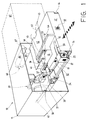
- the device 10 consists substantially in an external casing 11, and a drawer table 12 capable of sliding horizontally in relation to the casing 11.
- the external casing 11 exhibits a boxlike structure of compact dimensions, and is thus easily associated with any developing machine currently obtainable through commercial channels.
- the drawer table 12 is parallelepiped in shape with a rectangular base, and exhibits a full depth gap 13 on the side directed toward the interior of the casing 11 which extends longitudinally for some three quarters of the length of the drawer 12.
- the sides of the drawer 12 are associated slidably with the adjacent walls of the casing 11 by way of precision telescopic runners 14 gliding on ball bearings.
- the drawer 12 is set in motion by a lead screw 15 (figs 4 and 7) mounted rotatably to the casing 11 and coupled with a lead nut 16 incorporated into the drawer.
- the screw 15 is driven by a geared motor 17, to which it is connected by way of gears 18 (fig 4).
- the longitudinal edges of the shelf 19 exhibit two channels 20 of which the function is to guide the flanged sliding edges 21 of a shuttle 22 in which the roll 23 of photographic film is accommodated.
- the shuttle 22 comprises a housing of box construction created by the union of a base element 24 with a cover element 25, both exhibiting an L-shaped cross section.
- the cover element 25 is hinged to the base element 24 along a horizontal axis and pivotable thus between an open position and a closed position.
- the inside face of the base element 24 affords arcuate supports 26 (fig 7) on which the roll of film 23 is positioned with its axis parallel to the longitudinal axis of the drawer 12.
- a suitably profiled metal leaf spring 27 associated with the inside face of the cover element 25 (fig 7) serves to retain the roll of film 23 resiliently in the correct position internally of the housing.
- the vertically disposed wall of the base element 24 of the shuttle 22 is furnished with openings 28 and 29 respectively affording a passage to the photographic film 30 (figs 1, 2 and 9) and exposing a bar code, applied to every roll, which identifies the physical and chemical specifications of the particular film.
- the lateral shelf 19 of the drawer 12 exhibits one open end, coinciding with the front face of the drawer 12, whereas the remaining end terminates against a vertical face 31 (figs 1 and 2) presented by the body of the drawer 12.
- the vertical flank wall of the drawer 12 affords a window 32 (fig 1); at a point coinciding with this same window 32, the body of the drawer 12 houses an optical device 33 capable of reading the bar code carried by each roll of film.
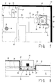
- the device comprises a carriage 34 occupying the same plane as the shelf 19 and furnished in like manner along the longitudinal edges with channels 35 (fig 8) identical to and aligned with the channels 20 of the shelf 19.
- the transverse edges of the carriage 34 are provided with further channels 36 (fig 8) designed to couple slidably with corresponding ways 37 projecting from the vertical walls of a transverse track 38 extending from the lateral shelf 19 to the gap 13 afforded by the drawer 12.
- the outermost longitudinal side of the carriage 34 is fitted with a wheel 39 (figs 1 and 2) rotatable about a vertical axis, of which the function will be described in due course, whilst the underside of the carriage 34 is connected to the transverse track 38 by a return spring 40 (fig 8) of which the function likewise will be described in due course.
- the top face of the drawer 12 carries a guillotine 41 (figs 1, 2 and 9) by which the photographic film 30 is cut square, a horizontal sheath 42 accommodating the leader 43 by which the film 30 is drawn forward, also a longitudinal ridge 44 extended at the end directed toward the casing 11 into a horizontal arm 45 of which the underside is embodied with a rack tooth profile 46.
- the guillotine 41 occupies a position at the innermost end of the transverse track 38 destined to accommodate the movement of the carriage 34, adjacent to the gap 13 in the drawer 12.
- the guillotine 41 is composed of a first blade 47 (fig 9), fixed in a horizontal position, and a second blade 48 mounted pivotably in relation to the first blade 47.
- the pivotable blade 48 is operated in conventional manner by an electromagnetic device 49, through the agency of conventional mechanical coupling means which are not described.
- the guillotine 41 is equipped with a transverse plate 50 of which the function is to restrain the film 30 in a horizontal position ready for trimming, and a safety guard 51 serving to prevent accidental access to the blades 47 and 48.
- the sheath 42 accommodating the leader 43 extends in a direction transverse to the longitudinal axis 12 of the drawer 12 and coaxially with the transverse track 38 accommodating the movement of the carriage 34.
- the mouth 52 of the sheath 42 lies adjacent to one lateral edge of the drawer 12, whereas its rear end 53 lies adjacent to the gap 13 afforded by the drawer 12, facing the transverse track 38 and the guillotine 41.
- the sheath 42 is of length such that the two take-up lugs 54 of the leader 43 are able to project from the mouth 52, for reasons to be described in due course.
- the rear end 53 of the sheath 42 is partially open so that the tail end 55 of the leader 43, which must be spliced to the photographic film 30, is able to emerge.
- a mechanical stop 56 and a proximity sensor 57 are also installed along the rear end 53 of the sheath 42, the functions of which being respectively to ensure correct positioning of the leader 43 and to enable operation of the loading device only after the leader 43 has been correctly inserted in the sheath 42.
- the longitudinal ridge 44 supporting the rack arm 45 extends inward from the front face of the drawer 12 and terminates at a point close to the sheath 42 containing the leader 43.
- the arm 45 occupies a position adjacent to the gap 13 in the drawer 12 and above the sheath 42 accommodating the leader 43, and performs a function that will be described in due course.
- the device 10 further comprises an angled surface 58 (figs 1, 2 and 3), a removable splicing mechanism 59 (figs 1, 4, 5 and 6), and a loading mechanism 60 by which the film 30 is directed into the developing machine 61 (indicated by phantom lines in figs 1 and 2).
- the angled surface 58 is generated orthogonally from the vertical wall of the casing 11 contiguous to the lateral shelf 19, and extends thus progressively toward the interior of the casing 11 to the point of merging with a rectilinear surface 62 disposed parallel to the selfsame vertical wall of the casing 11.
- the angled surface 58 is designed to interact with the vertically revolving wheel 39 of the carriage 34 in a manner to be described in due course.
- the splicing mechanism 59 is composed of a vertical baffle 63 (fig 5) carrying two reels 64 loaded with adhesive tape, and a guillotine type cutter device 65 with a relative solenoid actuator 66.
- the longitudinal edges of the vertical baffle 63 are slidably accommodated in corresponding horizontal channels 67 of "C" profile (figs 4 and 7) secured respectively to the top and bottom internal faces of the casing 11.
- the splicing mechanism 59 can be removed slidably from the casing 11 by pulling on a handle 68 (fig 5) that projects outward from the vertical front edge of the baffle 63.
- the top section of the vertical baffle 63 affords a slot 69 extending longitudinally from the vertical front edge to connect with a rectangular opening 70.
- the initial part of the longitudinal slot 69 exhibits splayed edges 71 designed to function as a funnel and is furnished, on the side of the baffle supporting the reels 64, with entry plates 72 projecting horizontally from the edges of the slot 69.
- Space is provided between the longitudinal slot 69 and the rectangular opening 70 for two pinch wheels 73 and 74 disposed one above the other and mounted in such a way as to rotate about respective horizontal axes.
- the lower wheel 73 is freely rotatable about a fixed axis.
- the upper wheel 74 is mounted rotatably to the end of a rocking lever 75 pivotably associated with a fulcrum denoted F. As indicated in fig 5, the lever 75 is constrained by a spring 76 to rotate in such a way as will force the relative upper wheel 74 against the lower wheel 73.
- the upper wheel 74 is also made to rotate about its own axis in a clockwise direction by two gears 77 and 78 (fig 6) mounted rotatably to the opposite side of the vertical baffle 63.
- a first gear 77 is mounted coaxially with the upper wheel 74 to the same rotating shaft.
- the second gear 78 is associated coaxially with the fulcrum pivot F and presents an internal toothed portion 79 of which the diameter is smaller than that of an external toothed portion 80.
- the internal portion 79 of smaller diameter meshes with the first gear 77, whereas the function of the larger diameter external portion 80 is to mesh with the rack 46 afforded by the arm 45 extending from the drawer 12, in a manner to be described in due course.
- the two reels 64 carrying the adhesive tape are freely revolving, and mounted so as to rotate about respective horizontal axes.
- the adhesive tapes are directed between the two pinch wheels 73 and 74, with the aid of an intermediate guide wheel 81 in the case of the tape uppermost, in such a way that their adhesive surfaces are mutually opposed.
- the cutter device 65 is disposed vertically between the pinch wheels 73-74 and the rectangular opening 70.
- the cutter device 65 comprises one fixed blade 82 and one moving blade 83.
- the moving blade 83 is shifted by the solenoid 66 toward the fixed blade 82 in such a way as to sever the tapes positioned between them, and returned by appropriate means to an at-rest position when the solenoid 66 is de-energized.
- the loading mechanism 60 by which the film 30 is fed into the developing machine 61 comprises two horizontal pinch rollers 85 and 86 positioned one above the other alongside a port 87 communicating with the machine 61.
- the top roller 86 is freely revolving, and rotatable about a movable axis.
- the bottom roller 85 is driven in rotation by a geared motor 88, to which it is coupled mechanically by way of transmission gears 89.
- the axis of rotation of the top roller 86 is able to slide vertically between a feed position, in which the top roller 86 impinges on the bottom roller 85, and a standby position in which the top roller 86 is elevated above the bottom roller 85.
- the elevation of the top roller 86 is brought about by energizing a solenoid 90 connected mechanically to the axis of rotation of the roller 86 (fig 4).
- the operation of the loading device 10 according to the invention is as follows.
- the roll 23 of photographic film 30 to be developed is inserted in the shuttle 22, which will be lying at the outermost end of the lateral shelf 19 of the drawer 12.
- the shuttle 22 is positioned such that the openings 28 and 29 affording passage to the film and exposing the bar code to the reader are directed toward the drawer table 12.
- the roll 23 passes in front of the window 32 and the optical device 33 will read the bar code containing the specifications of the film 30 to be developed. Given the requisite compatibility between the film 30 and the developing machine 61, the bar code reader 33 generates a signal to enable the loading procedure.
- Preparation of the loading device 10 also requires that the operator insert the leader 43 into the sheath 42, the effect of which is to switch the relative proximity sensor 57 to the position enabling operation of the device 10.
- the operator activates the device 10 by pressing a button 92 located on the front face of the drawer 12.
- the leading edge of the film 30 will be trimmed square by the guillotine 41 and the lead screw 15 begins turning in the relative nut 16 to traverse the drawer 12 into the casing 11.
- the vertically disposed wheel 30 of the carriage 34 enters into contact with the angled surface 58.
- the angled surface 58 occasions the movement of the carriage 34 along the transverse track 38 to the point at which the trimmed end of the film 30 is caused to coincide and match up with the tail end 55 of the leader 43, which will be projecting from the sheath 42 (the positions in question are indicated by phantom lines in fig 2).
- first gear 77 and the upper pinch wheel 74 are caused by the smaller diameter tooth profile 79 to rotate in the same direction as that followed by the drawer 12 as it advances with the ends of the film 30 and the leader 43 matched and taped.
- the arm 45 and the rack 46 contribute advantageously in decoiling the adhesive tapes 84 from the respective reels 64 and ensuring their correct positions on the opposite sides of the photographic film 30 and the leader 43.
- an appropriate sensor will pilot the operation of the solenoid 66 associated with the cutter device 65 and the adhesive tapes 84 are severed along the relative lateral edge of the film 30 and leader 43. It will be observed that, during the movement of the drawer 12 into the casing 11, the take-up lugs 54 of the leader 43 are directed into position between the two pinch rollers 85 and 86 of the loading mechanism 60 serving the developing machine 61, as indicated by the phantom lines in fig 2. Throughout this step in which the drawer 12 is introduced, the top roller 86 is in fact held at a distance from the bottom roller 85 by the action of the solenoid 90.
- the solenoid 90 will be de-energized, for example switched by the same sensor as that which pilots the operation of the cutter device 65, whereupon the top roller 86 is brought into contact with the bottom roller 85 to feed the leader 43 and the film 30 into the developing machine 61 by way of the communicating port 87.
- the loading operation concludes when the trailing end of the film 30 locks fast on emerging from the roll 23.
- the carriage 34 is subjected to a pulling force sufficient to overcome the strength of the return spring 40, and caused thus to advance along the transverse track 38 to the point of engaging a microswitch 93 which pilots the operation of the guillotine 41 positioned over the end of the track 38.
- the film 30 is cut by the guillotine 41, whereupon the carriage 34 is returned to a position of contact with the rectilinear surface 62 through the action of the spring 40.
- the shuttle 22 can be shaped and proportioned advantageously to accommodate rolls 23 of film 30 in different sizes, naturally with all the components envisaged for implementation of the various operations described above being suitably proportioned likewise; the movement of the shuttle 22, furthermore, instead of being controlled manually as aforementioned, might to advantage be controlled automatically using suitable motorized drive means of conventional type. It will be evident from the foregoing description that photographic film 30 can be loaded into a developing machine 61 by the device 10 according to the invention in a precise and correct manner, without the need for complicated manual interventions on the part of the operator, and, accordingly, the operation of loading the film 30 can be supervised by persons possessing no specialist skills or by persons without any particular training.
- the device 10 according to the invention exhibits overall dimensions so compact that it can be easily associated with or incorporated into developing machines currently in use.
Landscapes
- Physics & Mathematics (AREA)
- General Physics & Mathematics (AREA)
- Photographic Developing Apparatuses (AREA)
- Photographic Processing Devices Using Wet Methods (AREA)
Applications Claiming Priority (2)
| Application Number | Priority Date | Filing Date | Title |
|---|---|---|---|
| IT93PN000040A IT1265563B1 (it) | 1993-06-16 | 1993-06-16 | Dispositivo di caricamento automatico di pellicole fotografiche per macchine sviluppatrici |
| ITPN930040 | 1993-06-16 |
Publications (2)
| Publication Number | Publication Date |
|---|---|
| EP0629916A2 true EP0629916A2 (de) | 1994-12-21 |
| EP0629916A3 EP0629916A3 (de) | 1995-07-19 |
Family
ID=11394809
Family Applications (1)
| Application Number | Title | Priority Date | Filing Date |
|---|---|---|---|
| EP94201698A Withdrawn EP0629916A3 (de) | 1993-06-16 | 1994-06-14 | Automatische Ladevorrichtung für fotografische Filme in Entwicklungsmaschinen. |
Country Status (3)
| Country | Link |
|---|---|
| US (1) | US5495311A (de) |
| EP (1) | EP0629916A3 (de) |
| IT (1) | IT1265563B1 (de) |
Cited By (6)
| Publication number | Priority date | Publication date | Assignee | Title |
|---|---|---|---|---|
| EP0723198A1 (de) * | 1995-01-17 | 1996-07-24 | Noritsu Koki Co., Ltd. | Klebepresse |
| EP0679594A3 (de) * | 1994-04-25 | 1996-10-09 | Noritsu Koki Co Ltd | Verbindungstisch. |
| EP0764882A1 (de) * | 1995-09-19 | 1997-03-26 | Noritsu Koki Co., Ltd. | Filmkassettenbehälter |
| EP0769718A3 (de) * | 1995-10-19 | 1997-07-09 | Noritsu Koki Co Ltd | Vorratsbehälter für Behandlungsflüssigkeiten in einem automatischen Entwicklungssystem und photographische Behandlungsvorrichtung |
| US5796465A (en) * | 1995-10-05 | 1998-08-18 | Noritsu Koki Co., Ltd. | Automatic film development apparatus |
| EP0877290A1 (de) * | 1997-05-06 | 1998-11-11 | Gretag Imaging Ag | Prüfmaterialspeicher-und-zuführeinrichtung |
Families Citing this family (2)
| Publication number | Priority date | Publication date | Assignee | Title |
|---|---|---|---|---|
| US5826131A (en) * | 1996-12-26 | 1998-10-20 | Fuji Photo Film Co., Ltd. | Development processing apparatus |
| US6329886B1 (en) * | 1998-05-12 | 2001-12-11 | Nec Corporation | Impedance-matching method and circuit at different frequences |
Family Cites Families (7)
| Publication number | Priority date | Publication date | Assignee | Title |
|---|---|---|---|---|
| US4411725A (en) * | 1977-10-05 | 1983-10-25 | Cx Corporation | Daylight film splicer |
| US4543151A (en) * | 1983-07-18 | 1985-09-24 | Cx Corporation | Daylight apparatus for breaking open a film cassette, identifying the film released therefrom, and splicing same to the next preceding film |
| JPS63316860A (ja) * | 1987-06-19 | 1988-12-26 | Noritsu Kenkyu Center:Kk | フィルムとフィルムリ−ダ−とのオ−トスプライス装置 |
| DE3737796A1 (de) * | 1987-11-06 | 1989-05-18 | Agfa Gevaert Ag | Verfahren und vorrichtung zur entnahme fotografischer filme aus filmpatronen |
| US4894674A (en) * | 1988-09-22 | 1990-01-16 | Radov Mitchell C | Daylight bulk film loading system |
| IT1238633B (it) * | 1989-12-28 | 1993-08-31 | Gretag San Marco Srl | Caricatore di film per alimentare macchine sviluppatrici-film e dispositivo di preparazione di detto caricatore |
| JP2661826B2 (ja) * | 1991-10-30 | 1997-10-08 | 富士写真フイルム株式会社 | フィルム接合機 |
-
1993
- 1993-06-16 IT IT93PN000040A patent/IT1265563B1/it active IP Right Grant
-
1994
- 1994-06-14 EP EP94201698A patent/EP0629916A3/de not_active Withdrawn
- 1994-06-15 US US08/260,902 patent/US5495311A/en not_active Expired - Fee Related
Cited By (10)
| Publication number | Priority date | Publication date | Assignee | Title |
|---|---|---|---|---|
| EP0679594A3 (de) * | 1994-04-25 | 1996-10-09 | Noritsu Koki Co Ltd | Verbindungstisch. |
| US5650033A (en) * | 1994-04-25 | 1997-07-22 | Noritsu Koki Co., Ltd. | Splicing table |
| US5765071A (en) * | 1994-10-23 | 1998-06-09 | Noritsu Koki Co., Ltd. | Processing liquid storage apparatus in automatic developer system, and photographic processing apparatus |
| EP0723198A1 (de) * | 1995-01-17 | 1996-07-24 | Noritsu Koki Co., Ltd. | Klebepresse |
| EP0764882A1 (de) * | 1995-09-19 | 1997-03-26 | Noritsu Koki Co., Ltd. | Filmkassettenbehälter |
| US5803386A (en) * | 1995-09-19 | 1998-09-08 | Noritsu Koki Co., Ltd. | Film cartridge case |
| US5796465A (en) * | 1995-10-05 | 1998-08-18 | Noritsu Koki Co., Ltd. | Automatic film development apparatus |
| EP0769718A3 (de) * | 1995-10-19 | 1997-07-09 | Noritsu Koki Co Ltd | Vorratsbehälter für Behandlungsflüssigkeiten in einem automatischen Entwicklungssystem und photographische Behandlungsvorrichtung |
| EP0877290A1 (de) * | 1997-05-06 | 1998-11-11 | Gretag Imaging Ag | Prüfmaterialspeicher-und-zuführeinrichtung |
| US6059465A (en) * | 1997-05-06 | 2000-05-09 | Gretag Imaging Ag | Test material storage and feed device |
Also Published As
| Publication number | Publication date |
|---|---|
| ITPN930040A0 (it) | 1993-06-16 |
| IT1265563B1 (it) | 1996-11-22 |
| ITPN930040A1 (it) | 1994-12-16 |
| EP0629916A3 (de) | 1995-07-19 |
| US5495311A (en) | 1996-02-27 |
Similar Documents
| Publication | Publication Date | Title |
|---|---|---|
| EP0629916A2 (de) | Automatische Ladevorrichtung für fotografische Filme in Entwicklungsmaschinen | |
| US4797698A (en) | Film feeding apparatus | |
| US4638696A (en) | Apparatus for dispensing strip material or the like | |
| US4752797A (en) | Photographic camera | |
| US4472038A (en) | Photographic camera | |
| GB2130387A (en) | Film supporting apparatus for cameras | |
| DE1966308B2 (de) | Photographischer Apparat | |
| US4292115A (en) | Cartridge film unloading and splicing system | |
| US4949114A (en) | Device for introducing the free end of a photographic film to be developed, unwound from a reel, into a film developing unit | |
| US3800319A (en) | Cassette type tape recording and reproducing apparatus | |
| US3955779A (en) | Cartridge with removable take-up sub-cartridge | |
| EP0516105B1 (de) | Filmbehälter | |
| US4516386A (en) | Semi-automatic slide mounter with anti-reverse operating lever | |
| CA2009320C (en) | Cassette loading mechanism of a magnetic recording and reproducing apparatus | |
| US3265263A (en) | Method and apparatus for opening expendable film cartridges | |
| US3640480A (en) | Scroll stripping method and apparatus | |
| US5311232A (en) | Film magazine for feeding film developing machines and device for preparing said magazine | |
| JPH035735B2 (de) | ||
| JP2882565B2 (ja) | フィルム巻替装置 | |
| KR0185603B1 (ko) | 필름자동 되감기장치 | |
| US4894675A (en) | Apparatus for splicing together undeveloped customer films in a darkroom | |
| US4782546A (en) | Tape repair apparatus | |
| US4992811A (en) | Film advancing and rewinding mechanism | |
| US4817840A (en) | Apparatus for feeding leader tape | |
| US3587954A (en) | Cartridge opener |
Legal Events
| Date | Code | Title | Description |
|---|---|---|---|
| PUAI | Public reference made under article 153(3) epc to a published international application that has entered the european phase |
Free format text: ORIGINAL CODE: 0009012 |
|
| AK | Designated contracting states |
Kind code of ref document: A2 Designated state(s): DE ES FR GB |
|
| PUAL | Search report despatched |
Free format text: ORIGINAL CODE: 0009013 |
|
| AK | Designated contracting states |
Kind code of ref document: A3 Designated state(s): DE ES FR GB |
|
| STAA | Information on the status of an ep patent application or granted ep patent |
Free format text: STATUS: THE APPLICATION IS DEEMED TO BE WITHDRAWN |
|
| 18D | Application deemed to be withdrawn |
Effective date: 19960120 |