EP0629983A1 - Détecteur de fumée du type à transmission de lumière - Google Patents
Détecteur de fumée du type à transmission de lumière Download PDFInfo
- Publication number
- EP0629983A1 EP0629983A1 EP93310263A EP93310263A EP0629983A1 EP 0629983 A1 EP0629983 A1 EP 0629983A1 EP 93310263 A EP93310263 A EP 93310263A EP 93310263 A EP93310263 A EP 93310263A EP 0629983 A1 EP0629983 A1 EP 0629983A1
- Authority
- EP
- European Patent Office
- Prior art keywords
- radiation
- source
- sources
- receiver
- path
- Prior art date
- Legal status (The legal status is an assumption and is not a legal conclusion. Google has not performed a legal analysis and makes no representation as to the accuracy of the status listed.)
- Withdrawn
Links
Images
Classifications
-
- G—PHYSICS
- G08—SIGNALLING
- G08B—SIGNALLING SYSTEMS, e.g. PERSONAL CALLING SYSTEMS; ORDER TELEGRAPHS; ALARM SYSTEMS
- G08B17/00—Fire alarms; Alarms responsive to explosion
- G08B17/10—Actuation by presence of smoke or gases, e.g. automatic alarm devices for analysing flowing fluid materials by the use of optical means
- G08B17/103—Actuation by presence of smoke or gases, e.g. automatic alarm devices for analysing flowing fluid materials by the use of optical means using a light emitting and receiving device
Definitions
- This invention relates to a sensor for sensing the presence of species which absorb or scatter radiation, such as smoke particles in air, by means of changes in the attenuation of radiation transmitted through a medium, suitable for use in smoke (fire) detectors, in particular those referred to as point obscuration (or light extinction) fire detectors.
- the relative of importance of the scattering mechanisms depends on a number of factors, including the particle sizes and the wavelength of the radiation.
- optical beam smoke detectors in which a beam of radiation is arranged to travel near ceiling level along a path of sufficient length (typically >10m) for a significant level of attenuation to be caused by smoke concentrations characteristic of the presence of a fire in the same volume.
- optical beam smoke detectors are inconvenient to apply, and so called point smoke detectors are used.
- point smoke detectors are mounted on the ceiling of the protected volume and contain a sensitive device for detecting the presence of smoke in a chamber through which part of any airflow past the detector may by sampled.
- a number of techniques are currently used to sense the presence of smoke in the chamber, the most common being the ionisation chamber (used in ionisation smoke detectors), and light scattering (used in optical smoke detectors).
- an applied electric field causes an electrical current to flow in air which is ionised by particles emitted from a radioactive source.
- Smoke particles act as ion capture sites, causing a reduction in the current, which is sensed by an electronic circuit.
- a pulse of infrared radiation is emitted from a source into the chamber.
- Smoke particles scatter or reflect a small proportion of the radiation, and this is sensed by a receiver, mounted so that it cannot receive radiation from the source by a direct path.
- Many optical detectors use a scatter angle of about 45 degrees (forward scatter), which is found to offer a reasonable level of sensitivity together with a convenient arrangement. Detectors using predominant scatter angles between 90 and of 180 degrees (backwards scatter) are also known.
- the range of measured m values is seen to be significantly smaller than for the other parameters.
- An obscuration detector would therefore have a more even response in the four tests, and its overall level of sensitivity would not need to be so high, which would lower the risk of false alarms.
- the typical fire test gradings achieved by existing optical detectors and ionisation detectors indicates that a point obscuration fire detector could achieve a grading in all four tests equivalent to the best achieved by optical or ionisation detectors, if it had an alarm threshold corresponding to an m value of less than 0.40 dB/m. If the effective path length were 50 mm, this would correspond to a threshold obscuration signal level of a 0.46% reduction from the clean air signal. To achieve this with an acceptable stability and accuracy the sensor should ideally have:
- a point obscuration fire detector should also ideally:
- a point obscuration fire detector would have a number of additional advantages over existing point smoke detectors, eg:
- the principal technical difficulty is known to lie in achieving signal stability at the required sensitivity in a compact, low cost arrangement. This has not been achieved using known techniques.
- the main object of the present invention is to achieve a high level of signal stability in an obscuration sensor, permitting an adequate sensitivity to be achieved with a short radiation path length consistent with its use in a point obscuration fire detector.
- a sensor for sensing the presence of species in a medium which absorb or scatter radiation wherein visible or infra-red radiation is transmitted from at least two sources to a receiver along paths so arranged that the absorbing or scattering species attenuate a different proportion of the radiation transmitted along each path, characterized in that means are operable to subtract the signals resulting from the radiation received from one source from the signals resulting from the radiation received from another source and to sense the resulting difference signal, and wherein the ratio of the average energies radiated from the sources may be controlled by means of passing through the sources quantities of charge determined by gating a given current for times in a known ratio, so as to maintain the difference signal at zero or at a small proportion of the signal from one source, and wherein the ratio of the gating times, and the difference signal are analyzed in order to permit changes in the quantity of radiation attenuated by the species to be calculated.
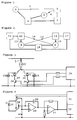
- two sources 1 and 2 are arranged to transmit radiation along paths 3 and 4 to a receiver 5. It is arranged such that the absorbing or scattering species attenuates a different proportion of the radiation in the two paths, for example by the paths being of different lengths, having a different degree of exposure to the species, or by the use of a different radiation wavelength in cases where the attenuation is known to be wavelength dependent.
- a control means 6 causes the sources to transmit radiation, the ratio of the radiant energies emitted by the sources being accurately controlled.
- the receiver 5 is connected to means 7 in which the signal received from one source is subtracted from the signal received from the other source and the difference between them is accurately sensed. The difference signal is used by the control means 6 as the basis for controlling the ratio of the energies emitted by the sources.
- the control means 7 may attempt to maintain the difference signal from the receiver at zero, in which case the changes in the absorption coefficient will an inverse function of the change in the ratio of the energies. In practice it is often found to be convenient to use both techniques in combination.
- control means 6 could routinely, under known conditions, change the ratio of the energies and measure the resultant change in the difference signal, and thereby calibrate the relationship between these two parameters.
- the fundamental advantage of this type of sensor is that a very high degree of resolution and stability may be achieved with a simple low cost arrangement. Because the difference signal can be maintained at a very small proportion of the signal received from either source, the stability of the receiver gain becomes relatively unimportant. If the ratio of the energies can be controlled to a good resolution, the difference signal need not be sensed to a high resolution. This permits the use of easily available, low cost the use of an 8-bit analogue to digital to convertor to measure the difference signal.
- the stability of the sensor depends on the ability to accurately control the ratio of the energies emitted by the sources. A preferred embodiment to control this is described later.
- LED pulsed light emitting diode
- the sensor arrangement using two source and one receiver can achieve a good performance. It will be understood however that the radiation emission efficiency of LED sources is quite strongly influenced by temperature, as well as by other factors. To achieve the very high levels of stability with temperature demanded by a point obscuration fire detector, the difference in temperature of the sources must be kept very small, and the temperature coefficients of emission of the individual sources must be very well matched.
- Sources 8 and 9 each transmit to receivers 10 and 11.
- Source 8 transmits via a path 12 to receiver 11 and via a different path 13 to receiver 10
- the source 9 transmits via a path 14 to receiver 11 and via a different path 15 to receiver 11.
- the absorbing or scattering species attenuates a different proportion of the radiation in path 12 to that in path 13, and similarly for paths 14 and 15.
- the receivers are connected to means 16 and 17 respectively, in each of which the signal received from one source may be subtracted from the signal received from the other source and the difference between them accurately sensed.
- Each difference signal is used separately by the control means 18 as the basis for controlling the ratio of the energies emitted by the sources, at different times during the sensor operation. In succession the signals from the two receivers are approximately balanced and the difference signals measured.
- FIGS 3 and 4 Preferred embodiments of the source, receiver and control circuitry are shown schematically in figures 3 and 4. These will be suitable for use in both the arrangement of figure 1 and of figure 2, at visible or near infra-red wavelengths (500nm to 1000nm), convenient for the sensing of smoke. For clarity only those parts of the circuitry are shown which are essential to the understanding of the present invention.
- Sources 19 and 20 are LEDs, such as GaAlAs devices available from a number of suppliers, which emit radiation efficiently at a wavelength around 880nm. LEDs convert electrical energy directly into radiation energy, the intensity of the radiation emitted being approximately proportional to the electrical current which is passed through them.
- a constant current source 21, passes a current I, which is switched for a time (t1) into a capacitor 22, then switched for another time (t2) into a second capacitor 23.
- Charge accumulated on capacitor 22 (I.t1) is subsequently discharged for a time (t3) shorter than t1 through source 19 via a transistor 24.
- Charge accumulated on capacitor 23 (I.t2) is discharged for a time (t4) shorter than t2 through source 20 via transistor 25.
- This process is repeated at an approximately constant rate until an equilibrium is reached, with almost exactly the same charge flowing into the capacitors 22 and 23 as is discharged respectively into the sources 19 and 20 during each charge and discharge cycle.
- the sources may be pulsed simultaneously, with the times t3 and t4 being identical, and this may be preferred with some receiver configurations.
- the sources are pulsed in sequence.
- the times t3 and t4 may be different, and in order to further improve the temperature stability it is found to be desirable that the discharge (pulse) time for each source is a near constant ratio of the charge time, ie t1/t3 and t2/t4 are maintained approximately constant.
- the times t1, t2, t3 and t4 are controlled by the microcomputer 26, but it will be understood that this could also be realised by other electronics means.
- FIG. 4 shows a receiver circuit, specifically disposed for use with the LED sources which emit pulses in sequence.
- the receiver 27 is a silicon photodiode which may be electrically connected in either polarity through a switching circuit 28 across the input connections of an operational amplifier 29 having a capacitor 30 connected between the inverting input and the output.
- the switches are controlled by the microcomputer 31 such that the receiver current is integrated on the capacitor 30 while radiation is being received from one source and then the switch connections are changed so that the receiver current is integrated in the opposite polarity while radiation is being received from the other source.
- the voltage at the output of amplifier 29 is amplified using a second operational amplifier 33, configured as a voltage amplifier, and any change in the amplified voltage resulting from the double integration is measured using an analogue to digital convertor 32, or by other electronic means.
- the receiver were always connected in one given polarity while radiation was being received from a given source, errors such as offsets in the operational amplifiers could result in an apparent change in the sensed obscuration.
- the receiver is connected in a given polarity for some instances of radiation being received from a given source, and is connected in the opposite polarity for other instances of radiation being received from the same source. By separately analysing the difference signals resulting from the two instances errors may be corrected.
- the switching circuits of the above embodiments may be conveniently realised using CMOS transmission gates, such as the 4053B type available from a number of suppliers.
- the operational amplifiers may conveniently be a TLC27M2 type supplied by Texas Instruments.
- the microcomputer may conveniently be a device selected from the MC68HC05 range supplied by Motorola.
- a phototransistor may be employed instead of a photodiode by using an alternative receiver circuit. It will be understood that the principle of operation is not fundamentally dependent on the detailed circuitry, or on the specification of the components used, and could be realised using a wide variety of electronics means.
- the times t1 and t2 may be typically controlled by a single chip microcomputer to a time resolution corresponding to one count of its internal timer. Because both t1 and t2 are derived from the same microcomputer clock, the ratio will be predictable and will not drift significantly with changes in the clock frequency. For a typical sensor, capable of operating with a power consumption suitable for use in a point obscuration fire detector, the internal timer could conveniently count every 16 microseconds and the times t1 and t2 could each be approximately 100 milliseconds. Using an 8-bit analogue to digital convertor to measure the difference signal would give a potential resolution better than 1 part in 1 million of the zero obscuration signal, at least 2 orders of magnitude better than the 0.02% in the specification.
- Second order effects within the electronics and opto-electronic components are likely to be present in practice which will result in the maximum theroretical performance not being achieved. It will be understood that that other measures may be taken in the design of the optics, electronics, and in the signal processing within the microcomputer to minimise or correct for these.
- Embodiments of the sensor could utilise a wide variety of known optical techniques and physical arrangements. In practice it is found particularly convenient to expose both active and reference paths to smoke and to make the paths dissimilar in length. In order to maximise the difference in length at least one of the paths could be folded.
- folding does presents additional problems in a very low cost product with the quality of the reflectors or prisms and with the overall mechanical stability of the enclosure.
- more direct paths are used. The paths must be efficient and have a consistent performance, in order to prevent additional errors being introduced into the measurement of the absorption co-efficient.
- the embodiments described in the following text are given as examples which are found to offer good stability, together with a convenient mechanical arrangement.
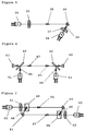
- Figure 5 shows an embodiment of sensor components for the arrangement in figure 1.
- An LED 34 and a lens 35 constitute one source, and an LED 36 and a lens 37 constitute the other source. Radiation impinges on a receiver photodiode 40 via a long path 38 and a short path 39.
- the lenses 35 and 37 may have different focal lengths in order to more nearly equalise the radiation energies, or lens 37 may be omitted entirely.
- Figure 6 shows a first embodiment of sensor components for the arrangement of figure 2.
- the sources comprise LEDs 41 and 42, and the receivers photodiodes 43 and 44.
- Beam splitting devices 49 and 50 result in two longer paths 45 and 47 and two shorter paths 46 and 48.
- the longer paths 45, 47 are combined for part of their length, but it may be arranged for the effect of insects present on the surface of one of the beam splitters to be resolved by the different effect on the pairs of beams.
- a second embodiment is shown in figure 7.
- the same components are shown with the (optional) addition of lenses 51 and 52.
- the principle is identical to that in the previous embodiment, but in this case the paths 45 and 47 are separated.
- the beam splitters may be constructed from etched metal grids, from arrays of plastic prisms in an injection moulded acrylic plate, or by other techniques.
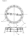
- Figure 8 shows a possible arrangement of the sensor embodiment of figure 7 within the envelope of a point smoke detector.
- the sensor assembly mounted between a member 53 and a member 54 enclosed within an outer case 55 provided with apertures 56.
- a screen 57 excludes insects and other larger objects.
- the LEDs and photodiodes are connected to a printed circuit board 58, which would also mount the necessary electronic circuitry.
- Other components (not shown) would permit the unit to be mounted on a surface and would provide an electrical interface to a fire detection and alarm system, as necessary.
- the mechanical components would be of injection moulded plastics, or metal as appropriate to the detailed design.
Landscapes
- Chemical & Material Sciences (AREA)
- Analytical Chemistry (AREA)
- Business, Economics & Management (AREA)
- Emergency Management (AREA)
- Physics & Mathematics (AREA)
- General Physics & Mathematics (AREA)
- Fire-Detection Mechanisms (AREA)
- Investigating Or Analysing Materials By Optical Means (AREA)
Applications Claiming Priority (2)
| Application Number | Priority Date | Filing Date | Title |
|---|---|---|---|
| GB9311311 | 1993-06-02 | ||
| GB9311311A GB2267963B (en) | 1992-06-04 | 1993-06-02 | Obscuration sensor |
Publications (1)
| Publication Number | Publication Date |
|---|---|
| EP0629983A1 true EP0629983A1 (fr) | 1994-12-21 |
Family
ID=10736458
Family Applications (1)
| Application Number | Title | Priority Date | Filing Date |
|---|---|---|---|
| EP93310263A Withdrawn EP0629983A1 (fr) | 1993-06-02 | 1993-12-17 | Détecteur de fumée du type à transmission de lumière |
Country Status (1)
| Country | Link |
|---|---|
| EP (1) | EP0629983A1 (fr) |
Cited By (3)
| Publication number | Priority date | Publication date | Assignee | Title |
|---|---|---|---|---|
| EP0813178A1 (fr) * | 1996-06-13 | 1997-12-17 | Cerberus Ag | Détecteur de fumée optique |
| GB2334096A (en) * | 1998-02-05 | 1999-08-11 | Hochiki Co | Attenuation smoke detector with drift compensation |
| WO2000063863A1 (fr) * | 1999-04-16 | 2000-10-26 | University Of Science And Technology Of China | Procede de detection d'incendies sensible a la fumee a images interceptant la lumiere |
Citations (8)
| Publication number | Priority date | Publication date | Assignee | Title |
|---|---|---|---|---|
| US4017193A (en) * | 1976-03-02 | 1977-04-12 | Leo Loiterman | Apparatus for measuring the transmittance or opacity of a gaseous medium carrying particulate matter through a conduit |
| US4237453A (en) * | 1979-03-23 | 1980-12-02 | Malinowski William J | Smoke detection system and method |
| WO1981002633A1 (fr) * | 1980-03-06 | 1981-09-17 | Baxter Travenol Lab | Dispositif et procede photometriques |
| JPS56153239A (en) * | 1980-04-26 | 1981-11-27 | Fuji Electric Co Ltd | Measuring device for organic polluting component in water |
| CH643061A5 (en) * | 1980-01-18 | 1984-05-15 | Zellweger Uster Ag | Method for measuring objects, device for carrying out the method, and application of the method |
| EP0119618A2 (fr) * | 1983-03-18 | 1984-09-26 | Erwin Sick GmbH Optik-Elektronik | Appareil optique pour la mesure de la transmission |
| DE3615259A1 (de) * | 1986-05-06 | 1987-11-12 | Krieg Gunther | Verfahren und system zur kontinuierlichen bestimmung der konzentrationen von molekuehlverbindungen in fluessigkeiten und gasen |
| US4838698A (en) * | 1986-04-07 | 1989-06-13 | Hochiki Corp. | Extinction type detector |
-
1993
- 1993-12-17 EP EP93310263A patent/EP0629983A1/fr not_active Withdrawn
Patent Citations (8)
| Publication number | Priority date | Publication date | Assignee | Title |
|---|---|---|---|---|
| US4017193A (en) * | 1976-03-02 | 1977-04-12 | Leo Loiterman | Apparatus for measuring the transmittance or opacity of a gaseous medium carrying particulate matter through a conduit |
| US4237453A (en) * | 1979-03-23 | 1980-12-02 | Malinowski William J | Smoke detection system and method |
| CH643061A5 (en) * | 1980-01-18 | 1984-05-15 | Zellweger Uster Ag | Method for measuring objects, device for carrying out the method, and application of the method |
| WO1981002633A1 (fr) * | 1980-03-06 | 1981-09-17 | Baxter Travenol Lab | Dispositif et procede photometriques |
| JPS56153239A (en) * | 1980-04-26 | 1981-11-27 | Fuji Electric Co Ltd | Measuring device for organic polluting component in water |
| EP0119618A2 (fr) * | 1983-03-18 | 1984-09-26 | Erwin Sick GmbH Optik-Elektronik | Appareil optique pour la mesure de la transmission |
| US4838698A (en) * | 1986-04-07 | 1989-06-13 | Hochiki Corp. | Extinction type detector |
| DE3615259A1 (de) * | 1986-05-06 | 1987-11-12 | Krieg Gunther | Verfahren und system zur kontinuierlichen bestimmung der konzentrationen von molekuehlverbindungen in fluessigkeiten und gasen |
Non-Patent Citations (1)
| Title |
|---|
| PATENT ABSTRACTS OF JAPAN vol. 6, no. 34 (P - 104)<912> 2 March 1982 (1982-03-02) * |
Cited By (5)
| Publication number | Priority date | Publication date | Assignee | Title |
|---|---|---|---|---|
| EP0813178A1 (fr) * | 1996-06-13 | 1997-12-17 | Cerberus Ag | Détecteur de fumée optique |
| GB2334096A (en) * | 1998-02-05 | 1999-08-11 | Hochiki Co | Attenuation smoke detector with drift compensation |
| US6094143A (en) * | 1998-02-05 | 2000-07-25 | Hochiki Corporation | Light obstruction type smoke sensor |
| GB2334096B (en) * | 1998-02-05 | 2002-05-29 | Hochiki Co | Light obstruction type smoke sensor |
| WO2000063863A1 (fr) * | 1999-04-16 | 2000-10-26 | University Of Science And Technology Of China | Procede de detection d'incendies sensible a la fumee a images interceptant la lumiere |
Similar Documents
| Publication | Publication Date | Title |
|---|---|---|
| US4665311A (en) | Smoke detecting apparatus | |
| CA1331649C (fr) | Methode servant a faire fonctionner un detecteur de fumee optique, et detecteur connexe | |
| CN107478612B (zh) | 用于检测过滤器积尘的传感器及方法 | |
| US4185278A (en) | Obscuration type smoke detector | |
| US4242673A (en) | Optical particle detector | |
| GB2397122A (en) | Smoke detector with a low false alarm rate | |
| US3495089A (en) | Alignment sensing devices utilizing light-emitting semi-conductors | |
| US3774039A (en) | Photoelectric apparatus for detecting light reflected from an object | |
| GB2267963A (en) | Obscuration sensor | |
| US4045675A (en) | Solid state radiation detector system | |
| GB2314618A (en) | Smoke detector using light scatter and extinction | |
| US4560874A (en) | Reference channel for sensing optical contamination | |
| GB1572885A (en) | Smoke detector | |
| IL113653A (en) | Active infrared sensor | |
| JPS6217693B2 (fr) | ||
| US4647786A (en) | Photoelectric smoke detector and its application | |
| GB2273769A (en) | Proportional light scattering sensor for particles | |
| KR910000271B1 (ko) | 화재 감지장치 | |
| CA1110344A (fr) | Detecteur de fumee electro-optique haute performance | |
| RU2426982C2 (ru) | Способ обнаружения пылеотложения на печатных платах радиоэлектронной аппаратуры | |
| EP0099729A1 (fr) | Détecteur pour des particules suspendues | |
| JPS6122278Y2 (fr) | ||
| JPS6049857B2 (ja) | 視界測定装置 | |
| KR100493982B1 (ko) | 개선된 잡음 허용 범위를 갖는 검출 시스템 | |
| EP0066370A1 (fr) | Canal de référence pour déterminer le degré de salissure d'éléments optiques |
Legal Events
| Date | Code | Title | Description |
|---|---|---|---|
| PUAI | Public reference made under article 153(3) epc to a published international application that has entered the european phase |
Free format text: ORIGINAL CODE: 0009012 |
|
| AK | Designated contracting states |
Kind code of ref document: A1 Designated state(s): AT BE CH DE DK ES FR GB GR IE IT LI LU MC NL PT SE |
|
| 17P | Request for examination filed |
Effective date: 19950331 |
|
| STAA | Information on the status of an ep patent application or granted ep patent |
Free format text: STATUS: THE APPLICATION IS DEEMED TO BE WITHDRAWN |
|
| 18D | Application deemed to be withdrawn |
Effective date: 19970701 |