EP0630022A2 - Aufzeichnungsträgersteuerung mit Anwendung von Steuerungsbereichen, die nur bei einer Laufwerkvorrichtung zugreifbar sind - Google Patents
Aufzeichnungsträgersteuerung mit Anwendung von Steuerungsbereichen, die nur bei einer Laufwerkvorrichtung zugreifbar sind Download PDFInfo
- Publication number
- EP0630022A2 EP0630022A2 EP94303410A EP94303410A EP0630022A2 EP 0630022 A2 EP0630022 A2 EP 0630022A2 EP 94303410 A EP94303410 A EP 94303410A EP 94303410 A EP94303410 A EP 94303410A EP 0630022 A2 EP0630022 A2 EP 0630022A2
- Authority
- EP
- European Patent Office
- Prior art keywords
- data
- storage medium
- drive
- tape
- partition
- Prior art date
- Legal status (The legal status is an assumption and is not a legal conclusion. Google has not performed a legal analysis and makes no representation as to the accuracy of the status listed.)
- Withdrawn
Links
Images



Classifications
-
- G—PHYSICS
- G06—COMPUTING OR CALCULATING; COUNTING
- G06F—ELECTRIC DIGITAL DATA PROCESSING
- G06F3/00—Input arrangements for transferring data to be processed into a form capable of being handled by the computer; Output arrangements for transferring data from processing unit to output unit, e.g. interface arrangements
- G06F3/06—Digital input from, or digital output to, record carriers, e.g. RAID, emulated record carriers or networked record carriers
- G06F3/0601—Interfaces specially adapted for storage systems
-
- G—PHYSICS
- G11—INFORMATION STORAGE
- G11B—INFORMATION STORAGE BASED ON RELATIVE MOVEMENT BETWEEN RECORD CARRIER AND TRANSDUCER
- G11B15/00—Driving, starting or stopping record carriers of filamentary or web form; Driving both such record carriers and heads; Guiding such record carriers or containers therefor; Control thereof; Control of operating function
- G11B15/02—Control of operating function, e.g. switching from recording to reproducing
-
- G—PHYSICS
- G11—INFORMATION STORAGE
- G11B—INFORMATION STORAGE BASED ON RELATIVE MOVEMENT BETWEEN RECORD CARRIER AND TRANSDUCER
- G11B20/00—Signal processing not specific to the method of recording or reproducing; Circuits therefor
- G11B20/10—Digital recording or reproducing
- G11B20/12—Formatting, e.g. arrangement of data block or words on the record carriers
- G11B20/1201—Formatting, e.g. arrangement of data block or words on the record carriers on tapes
- G11B20/1202—Formatting, e.g. arrangement of data block or words on the record carriers on tapes with longitudinal tracks only
- G11B20/1205—Formatting, e.g. arrangement of data block or words on the record carriers on tapes with longitudinal tracks only for discontinuous data, e.g. digital information signals or computer program data
-
- G—PHYSICS
- G11—INFORMATION STORAGE
- G11B—INFORMATION STORAGE BASED ON RELATIVE MOVEMENT BETWEEN RECORD CARRIER AND TRANSDUCER
- G11B20/00—Signal processing not specific to the method of recording or reproducing; Circuits therefor
- G11B20/10—Digital recording or reproducing
- G11B20/18—Error detection or correction; Testing, e.g. of drop-outs
- G11B20/1883—Methods for assignment of alternate areas for defective areas
-
- G—PHYSICS
- G11—INFORMATION STORAGE
- G11B—INFORMATION STORAGE BASED ON RELATIVE MOVEMENT BETWEEN RECORD CARRIER AND TRANSDUCER
- G11B23/00—Record carriers not specific to the method of recording or reproducing; Accessories, e.g. containers, specially adapted for co-operation with the recording or reproducing apparatus ; Intermediate mediums; Apparatus or processes specially adapted for their manufacture
- G11B23/30—Record carriers not specific to the method of recording or reproducing; Accessories, e.g. containers, specially adapted for co-operation with the recording or reproducing apparatus ; Intermediate mediums; Apparatus or processes specially adapted for their manufacture with provision for auxiliary signals
- G11B23/36—Signals on record carriers or on containers and recorded by the same method as the main recording
-
- G—PHYSICS
- G11—INFORMATION STORAGE
- G11B—INFORMATION STORAGE BASED ON RELATIVE MOVEMENT BETWEEN RECORD CARRIER AND TRANSDUCER
- G11B27/00—Editing; Indexing; Addressing; Timing or synchronising; Monitoring; Measuring tape travel
- G11B27/10—Indexing; Addressing; Timing or synchronising; Measuring tape travel
- G11B27/102—Programmed access in sequence to addressed parts of tracks of operating record carriers
- G11B27/107—Programmed access in sequence to addressed parts of tracks of operating record carriers of operating tapes
-
- G—PHYSICS
- G11—INFORMATION STORAGE
- G11B—INFORMATION STORAGE BASED ON RELATIVE MOVEMENT BETWEEN RECORD CARRIER AND TRANSDUCER
- G11B27/00—Editing; Indexing; Addressing; Timing or synchronising; Monitoring; Measuring tape travel
- G11B27/10—Indexing; Addressing; Timing or synchronising; Measuring tape travel
- G11B27/11—Indexing; Addressing; Timing or synchronising; Measuring tape travel by using information not detectable on the record carrier
-
- G—PHYSICS
- G11—INFORMATION STORAGE
- G11B—INFORMATION STORAGE BASED ON RELATIVE MOVEMENT BETWEEN RECORD CARRIER AND TRANSDUCER
- G11B27/00—Editing; Indexing; Addressing; Timing or synchronising; Monitoring; Measuring tape travel
- G11B27/10—Indexing; Addressing; Timing or synchronising; Measuring tape travel
- G11B27/11—Indexing; Addressing; Timing or synchronising; Measuring tape travel by using information not detectable on the record carrier
- G11B27/13—Indexing; Addressing; Timing or synchronising; Measuring tape travel by using information not detectable on the record carrier the information being derived from movement of the record carrier, e.g. using tachometer
-
- G—PHYSICS
- G11—INFORMATION STORAGE
- G11B—INFORMATION STORAGE BASED ON RELATIVE MOVEMENT BETWEEN RECORD CARRIER AND TRANSDUCER
- G11B27/00—Editing; Indexing; Addressing; Timing or synchronising; Monitoring; Measuring tape travel
- G11B27/10—Indexing; Addressing; Timing or synchronising; Measuring tape travel
- G11B27/19—Indexing; Addressing; Timing or synchronising; Measuring tape travel by using information detectable on the record carrier
- G11B27/28—Indexing; Addressing; Timing or synchronising; Measuring tape travel by using information detectable on the record carrier by using information signals recorded by the same method as the main recording
-
- G—PHYSICS
- G11—INFORMATION STORAGE
- G11B—INFORMATION STORAGE BASED ON RELATIVE MOVEMENT BETWEEN RECORD CARRIER AND TRANSDUCER
- G11B27/00—Editing; Indexing; Addressing; Timing or synchronising; Monitoring; Measuring tape travel
- G11B27/10—Indexing; Addressing; Timing or synchronising; Measuring tape travel
- G11B27/19—Indexing; Addressing; Timing or synchronising; Measuring tape travel by using information detectable on the record carrier
- G11B27/28—Indexing; Addressing; Timing or synchronising; Measuring tape travel by using information detectable on the record carrier by using information signals recorded by the same method as the main recording
- G11B27/32—Indexing; Addressing; Timing or synchronising; Measuring tape travel by using information detectable on the record carrier by using information signals recorded by the same method as the main recording on separate auxiliary tracks of the same or an auxiliary record carrier
- G11B27/327—Table of contents
- G11B27/328—Table of contents on a tape [TTOC]
-
- G—PHYSICS
- G11—INFORMATION STORAGE
- G11B—INFORMATION STORAGE BASED ON RELATIVE MOVEMENT BETWEEN RECORD CARRIER AND TRANSDUCER
- G11B27/00—Editing; Indexing; Addressing; Timing or synchronising; Monitoring; Measuring tape travel
- G11B27/36—Monitoring, i.e. supervising the progress of recording or reproducing
-
- G—PHYSICS
- G11—INFORMATION STORAGE
- G11B—INFORMATION STORAGE BASED ON RELATIVE MOVEMENT BETWEEN RECORD CARRIER AND TRANSDUCER
- G11B5/00—Recording by magnetisation or demagnetisation of a record carrier; Reproducing by magnetic means; Record carriers therefor
- G11B5/008—Recording on, or reproducing or erasing from, magnetic tapes, sheets, e.g. cards, or wires
- G11B5/00813—Recording on, or reproducing or erasing from, magnetic tapes, sheets, e.g. cards, or wires magnetic tapes
- G11B5/00817—Recording on, or reproducing or erasing from, magnetic tapes, sheets, e.g. cards, or wires magnetic tapes on longitudinal tracks only, e.g. for serpentine format recording
-
- G—PHYSICS
- G06—COMPUTING OR CALCULATING; COUNTING
- G06F—ELECTRIC DIGITAL DATA PROCESSING
- G06F3/00—Input arrangements for transferring data to be processed into a form capable of being handled by the computer; Output arrangements for transferring data from processing unit to output unit, e.g. interface arrangements
- G06F3/06—Digital input from, or digital output to, record carriers, e.g. RAID, emulated record carriers or networked record carriers
- G06F3/0601—Interfaces specially adapted for storage systems
- G06F3/0668—Interfaces specially adapted for storage systems adopting a particular infrastructure
- G06F3/0671—In-line storage system
- G06F3/0673—Single storage device
- G06F3/0682—Tape device
-
- G—PHYSICS
- G11—INFORMATION STORAGE
- G11B—INFORMATION STORAGE BASED ON RELATIVE MOVEMENT BETWEEN RECORD CARRIER AND TRANSDUCER
- G11B2220/00—Record carriers by type
- G11B2220/40—Combinations of multiple record carriers
- G11B2220/41—Flat as opposed to hierarchical combination, e.g. library of tapes or discs, CD changer, or groups of record carriers that together store one title
-
- G—PHYSICS
- G11—INFORMATION STORAGE
- G11B—INFORMATION STORAGE BASED ON RELATIVE MOVEMENT BETWEEN RECORD CARRIER AND TRANSDUCER
- G11B2220/00—Record carriers by type
- G11B2220/60—Solid state media
- G11B2220/65—Solid state media wherein solid state memory is used for storing indexing information or metadata
-
- G—PHYSICS
- G11—INFORMATION STORAGE
- G11B—INFORMATION STORAGE BASED ON RELATIVE MOVEMENT BETWEEN RECORD CARRIER AND TRANSDUCER
- G11B2220/00—Record carriers by type
- G11B2220/90—Tape-like record carriers
-
- G—PHYSICS
- G11—INFORMATION STORAGE
- G11B—INFORMATION STORAGE BASED ON RELATIVE MOVEMENT BETWEEN RECORD CARRIER AND TRANSDUCER
- G11B2220/00—Record carriers by type
- G11B2220/90—Tape-like record carriers
- G11B2220/95—Serpentine format, wherein a single track or group of tracks traverses the tape plural times from one end to the other
Definitions
- This invention relates to data storage devices including control of record media by a device independently of attaching host processors and the like.
- Prior data storage subsystems required host processor intervention in data storage subsystem operations for performing high speed searches (tape head is not in contact with the tape that is moving faster than tape speed during reading or writing), scanning a record medium (a slow speed search wherein the head is in transducing contact with the tape for reading block ID's, for example), particularly a magnetic tape medium, until a desired logical block is located on the record medium.
- This situation creates undesired performance problems in those data storage systems employing record media that stores an order of magnitude more data than prior are record media.
- Eliminating or reducing the prior art required host intervention in other aspects of data storage subsystems also increases the efficiency of host processor operations in that attention needed to operate with data storage subsystem operations has been eased.
- the prior art provided a directory in each record media that is created, updated and managed by software in a host processor attached to a data storage subsystem.
- a directory in which a directory is created, updated and managed by software in a host processor attached to a data storage subsystem.
- a volume table of contents (VTOC) another name for a directory recorded on a record medium, for an optical disk file is created, updated and managed by an attaching personal computer, a low performance host processor.
- VTOC included status of addressable data-storage areas on the optical disk data storage medium.
- Other prior art data storage systems employ similar techniques.
- Such record medium stored directories typically included addressing capability requiring a host processor to execute software that addresses a medium, rather than allowing a data storage subsystem to address internal data structures of a record medium independently of host processor software. It is desired to remove dependency of addressing internal data structures of a record medium from host processor executed software.
- An example representative of such addressing directories is shown in Kulakowski et al US patent 4,575,827.
- Magnetic tape record media also often included host created, updated and managed records that enabled host processor software to access records stored in a magnetic tape volume. As stated in Kulakowski et al, such control records were termed "tape table of contents", TTOC, rather than VTOC.
- the present invention provides a peripheral device (hereinafter drive) addressable area (herein device partition) that is not addressable by host processor software that enables the peripheral drive to create, update and manage directories and other volume-related data structures with respect to data stored in a data storage volume.
- Such data structures are data block map (hereinafter DBM) that addressably identifies not only host processor addressable data blocks but subsystem data blocks that may or may not be addressable by an attaching host processor.
- DBM data block map
- Such DBM enables a peripheral drive to execute high speed locate for rapidly finding a host processor addressable data block or a peripheral drive or drive only addressable data block. Physical medium locations are identified in the DBM.
- a peripheral drive such as a magnetic tape drive has a reel tachometer indicator that meters magnetic tape displacement for providing tape displacement addressability of a magnetic tape that facilitates high speed searching or locating data blocks.
- a plurality of reference physical locations or points are established for facilitating high speed (tape movement that is not in contact with a head). Such locations are not identified on the tape, per se, rather are measured and indicated by a suitable tape displacement meter, such as a reel tachometer.
- the status of the DBM and of the physical volume is indicated in the peripheral drive only addressable area. Such status is useful for removable media.
- the status for a removable medium is either mounted or demounted as indicated in a mount-demount indicator block (MDI). Such status also indicates whether or not the DBM has been logically "checked out” or removed from the record medium, i.e. if a record medium is mounted, then only a drive copy of the DBM is valid.
- a record medium may be loaded into a peripheral drive but not have a mounted status. Similarly, a fixed medium may not have a mounted status.
- Mounted status in a peripheral drive requires that a separate copy of the DBM be stored within the peripheral drive that is not on the record medium to which the DBM pertains. Such separate copy may be stored in a RAM.
- the peripheral drive changing the record medium status from mounted to demounted (whether or not the record medium is to be removed from the peripheral drive) validates the copy(s) in the record medium. Loading a record medium into a peripheral drive having the mount status indicates to the peripheral drive that the DBM is not valid.
- a directory of peripheral drive readable "end-of-data” (EOD) data block or tape marks enables high speed locate to the last written EOD that signifies the end of data of a record medium.
- EOD blocks are used to high speed locate to end of data in so-called partitions in a magnetic tape.
- a plurality of said DBM's and MDI's are recorded in the drive addressable area.
- Each DBM copy has an associated MDI copy such that if only one of many copies is valid, a peripheral drive can still employ, update and manage the DBM.
- a peripheral drive constructed using the present invention verifies upon a mount request that a loaded record medium has a valid copy of its DBM.
- the peripheral drive does not respond with a mounted message to a requesting host processor until after a valid copy of DBM is copied into the peripheral drive and all of the MDI's on the record medium are recorded as showing the record medium is mounted.
- a tape drive 10 is connected (attached) to other units 12 via peripheral controller 11.
- a direct connection without controller 11 is also contemplated.
- Other units 12 represent computers of all types, communication systems, local networks and the like.
- a tape cartridge 17 containing a single spool 20 of magnetic tape 21 is removably inserted into tape drive 10.
- Tape cartridge 17 shown in a play position operatively connects a spool motor and tachometer 22 to tape spool 20 for unreeling and reeling tape 21.
- Tape 21 is automatically threaded (in a known manner) past laterally-positionable multi-track multi-gap head 27 to machine reel 25.
- Data are transferred between tape 21 and other units 12 via data flow 28.
- Data flow 28 performs the usual formatting, error detecting and correcting, and other processing of information-bearing signals (data) found in magnetic tape recording apparatus.
- Motor and tachometer 26 rotate spool 26 in synchronism with spool 20, as is known. Lines 23 denote control and sensing signal transfer between motors 22 and 26 with tape drive control 30.
- Control 30 includes the usual programmed control for controlling data flow 28 and communicating with other units 12.
- Cartridge present sensor 31 senses the cartridge 17 for informing control 30 that cartridge 17 has been loaded into tape drive 10.
- Random access memory (RAM) 33 buffers data for data flow 28, stores control information for control 30 and may store an operating program for programmed control 30.
- control 30 may employ a read only memory (ROM) (not shown) for containing its program elements.
- ROM read only memory
- Of interest to the present invention is the storage of a separate copy of the Data Block Map (DBM) 34 and a separate copy of a statistical analysis recording system (SARS) 35 in RAM 33. These last two items are stored in tape 21 in a portion that is addressable only by peripheral drive 10, as will become more apparent.
- DBM Data Block Map
- SARS statistical analysis recording system
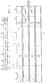
- Tape 21 includes triple longitudinally-extending laterally-spaced-apart redundant identical longitudinally-extending servo areas 40-42 for laterally relatively position tape 21 and head 27 in four relative positions.
- a drive to tape calibration area is disposed between dashed lines 50 and 52. This area contains signals (not described) that enable tape drive 10 to calibrate its operation to the particular characteristics of the loaded tape 21.
- the tape area between dashed line 52 and a hub end of tape 21 is available for recording.
- the later described track groups 0-3 respectively have a beginning of wrap (BOW) tape control block (not shown) longitudinally adjacent dashed line 52 and a end of wrap block (EOW) 59 at the hub end near line 56.
- Dashed lines 54 respectively indicate addressable logical partitions each of which is a collection of contiguous sectors that are indicated and addressed using tachometer 22.
- dashed lines can either denote such tachometer 22 indicated tape displacement locations for all data tracks or for only selected data tracks.
- numeral 58 denotes four track groups 0-3 used in a constructed embodiment and as best seen in Fig. 3. Serial recording proceeds from track group 0 through track group 3, no limitation thereto intended.
- the dashed line 54 indicated displacement locations preferably relate to tracks only in the respective track groups 0-3. Track portions between longitudinally adjacent ones of the dashed lines 54 are partitions. Dashed line 56 indicates approaching the hub end of tape 21. In each of the track groups, line 56 may be at a different longitudinal position. For example, if a medium defect X is longitudinally adjacent the hub end of tape 21 affects data tracks in track groups 0 and 2 but not 1 and 3, then a end of wrap data block EOW 59 (later described) is recorded in groups 0 and 2 tracks for shortening the data track lengths while an identical end of wrap block EOW 59 is written in track groups 1 and 3 at dashed line 56.
- Detected media defects remote from either longitudinal end of tape 21 are identified by a pair of so-called servo defect blocks (SDB), tape control blocks, that respectively are immediately upstream and downstream from the detected defect for defining a limited portion of a group of data tracks in one of the track groups 0-3 that is not available for recording because servo areas 40-42 are affected by the medium defect.
- SDB servo defect blocks
- First track group 0 is laterally displaced from longitudinal edges 57 respectively by tracks in track groups 3 and 1,2. Since track group 0 is a logical beginning of data recording, tape control information (DBM and SARS) is recorded in track group 0 in a so-called drive partition that exists between dashed lines 52 and a first dashed line 54. Such drive partition in track group 0 is only addressable by tape drive 10 and not by controller 11 nor other units 12. All other-units addressable partitions on tape 21 are arbitrarily numbered from 0 to a current maximum number of partitions. Each partition, whether a drive partition or an addressable partition, is a logical collection of contiguous sectors, each partition may have a different number of sectors.
- a sector (sometimes referred to as a segment) is a tachometer 22 determined length of tape and can be accessed by moving tape 21 and monitoring tachometer 22 generated count values (not shown). Any form of physical location addressing may be used, such as arbitrarily selected tachometer count values.
- First dashed line 54 does not apply to data tracks in track groups 1-3.
- Milligan et al in US patent 4,393,883 shows generating physical reference values (PRV) that are usable to identify the sectors on tape 21.
- Control information stored in the drive partition is useful to controller 11, other units 12 or tape drive 10 but such control information is addressable and readable only by peripheral drive 10.
- Tape drive 10 may supply such information to either controller or other units 12, as may be desired.
- the control information stored in the drive partition is that information primarily useful to tape drive 10 as it identifies physical locations on tape 21 of diverse control data elements useful for quickly locating data stored on tape 21, therefore it is referred to as storage medium physical access data.
- the usual prior art VTOC or TTOC may be stored in partition 0 for identifying to other units 12 the informational content of tape 21 including the logical data elements as partitions, logical volumes, files and the like. Control information shown in Fig.
- the illustrated drive partition may consist of a plurality of partitions, for example, a DBM partition for storing all copies of DBM, a SARS partition for storing all copies of SARS and a MDI partition for storing all copies of MDI. All other partitions are addressable, explicitly or implicitly by other units 12. Implicit addressing is by other units 12 addressing files, virtual volumes and the like.
- Tape drive 10 has the usual load point controls for positioning magnetic tape and magnetic head 27 to first read the tracks in track group 0.
- Control information in tape drive 10 created, updated and managed partition includes a format identification (FID) block 60 (Fig 4).
- FID 60 indicates that tape 21 is formatted as shown.
- All other control information is stored in K copies, K is an integer preferably 2 J where J is a positive integer, such as 3.
- Each block of control information is separated by a usual inter-block gap (IBG) 61.
- a first copy of the control information includes mount-demount indicator MDI block 63, copy 1 indicated by MDI 1, DBM 1 (copy 1 of K) and SARS 1 (copy 1 of K). All additional copies of the control information are represented by ellipsis 74.
- An end-of-data EOD tape control block 78 indicates the end of data in the tape drive accessed partition indicated by numeral 75.
- MDI 1 may be stored in the drive partition after SARS 1 69, i.e. between SARS 1 and EOD. Alternately, all MDI copies may be stored in one string of blocks, all DBM copies stored in a second string of blocks and all SARS copies stored in a third string of blocks. The sequence of storage in the drive partition is one of choice.
- Fig. 3 diagrammatically illustrates obtaining a maximal spacing between adjacent data tracks in each track group 0-3.
- Numerals 81-89 respectively indicate track clusters 1-8, and remaining track clusters, each track cluster having one track from each track group 0-3.
- Laterally adjacent track clusters have tracks scanned in opposite scanning directions 79 and 80.
- Magnetic tape 21 moves in a direction to the track scanning direction by magnetic head 27.
- the "to hub” scanning direction is caused by magnetic tape 21 being reeled from cartridge spool 20 while the “from hub” scanning direction is caused by magnetic tape being reeled onto cartridge spool 20.
- Magnetic tape 21 is scanned in a serpentine sequence. While magnetic head 27 is at one lateral (index) position, one serpentine scan (also termed a track wrap) occurs.
- All of the tracks are evenly spaced apart laterally, no limitation thereto intended.
- the concurrently accessed tracks of each track group are spaced apart by seven intervening tracks. For example, tracks 1 and 9, as determined by the equations above, are laterally separated by tracks 2 through 8.
- Such lateral spacing is maximum for all tracks and is the same for all successively numbered tracks in each track group. Note that the tracks of track group 2 in the even numbered track clusters are not accessed concurrently to the track group 2 tracks in odd numbered clusters. Also, the four data track areas 45-48 (Fig. 2) have a like number of tracks (each data track area has eight track clusters) such that the servo track areas 40-42 have a maximum lateral spacing. Such maximum lateral spacing is an optimum spacing for reducing errors caused by magnetic tape defects.
- a pair of unrecorded longitudinally-extending guard bands 43 separate the data track areas from each of the servo track areas 40-42.
- Numerals 54-A and 54-B respectively indicate different partition boundaries of a partition disposed adjacent the hub end of tape 21 and that spaces the EOW block 59 indicating end of wrap. Such partitions may also span BOW tape control blocks and extend between adjacent track groups. That is, a partition can begin in track group 0 and extend into track group 1. Also a partition can include the entirety of tape 21 recording area except for the drive partition.
- numeral 54-A indicates P's denoting location in each of the data tracks of track group 1 in an odd numbered cluster that is a partition leading boundary (first scanned in a forward direction of tape motion).
- numeral 54-B indicates an end of such partition in track group 1 but occurring in even numbered track clusters in scan direction 80.
- partition boundaries contain no special marks, that is, such boundaries are addressed by tape displacement.
- a partition-boundary-indicating tape control block may be used.
- data blocks as in the prior art, are addressed by other units 12 using block ID's.
- forward direction means tile direction of track scanning for writing data.
- Track scanning in a reverse direction is termed a backward direction.
- Tape 21 is transported between reels 20 and 25 in a reciprocating manner but the track scanning is in a forward direction or backward direction irrespective of actual tape direction of motion.
- upstream and downstream defining an item on tape with respect to a current tape position to respectively mean that an item is scanned either before or after said current position in the forward direction of scanning.
- Fig. 4 illustrates all of the data structures used herein.
- DBM 34 whether stored in RAM 33 or tape 21, has VOLID field 90 storing the volume ID or VOLID of the physical tape volume.
- the directories and maps in DBM 34 as described below include linked lists of a plurality of entries in the respective directories and maps. A pair of pointers point respectively to the beginning and end of each of the linked lists. Such lists can be singly or doubly linked.
- Tachometer count values in each directory indicate the respective tape displacement location in a forward direction of data track scanning. Tape lengths between successive tachometer counts are termed sectors.
- a partition is an addressable logical collection of contiguous sectors. Block ID's and other logical data indications may be included in any of the directories and maps.
- Partition directory 91 includes the forward direction tape displacement tachometer location of each partition along with a block ID identification of a first logical block in each partition.
- the partitions are enumerated in any numerical sequence, preferably from zero to a highest current numbered partition.
- the tape drive reserved partition between dashed lines 52-54 is not included in directory 91 as it is not addressable by other units 12. Both the sector and partition numerical sequences begin at the load point or beginning of track group 0, then proceed to the end of track group 0, thence to groups 1, 2 and 3 (in that order) such that the forward direction of scanning appears as one long tape medium, as indicated in Fig. 3.
- Tape mark directory 92 indicates the sector number of each tape mark on tape 21. Tape marks in the prior art were special recorded patterns for defining data file boundaries on data-storing magnetic tapes. In the described embodiment, such tape marks still indicate data file boundaries but are recorded as a later described tape control block. The tape mark directory is useful in connection with determining data file limits on tape 21 for selecting a tape moving algorithm as shown in Fig. 9.
- Servo demark directory 93 includes tachometer indications of locations of servo demark tape control blocks. Such demark tape control marks are link listed together in respective demarked media defect areas as later detailed.
- Logical volume directory 94 indicates the partitions having logical volumes and the tachometer number indicating location of each such logical volume. Logical volumes are addressable by other units 12 as if such logical volume was a physical volume. Such logical volumes contain their own respective block ID sequence that is independent of the block ID sequence used in the physical tape volume not included in such logical volume. Directory 94 may also contain other data particularly relating to logical characteristics of such logical volume. Tape drive 10 writes an EOD tape control block in each partition for indicating end of data recording. An empty partition optionally has an EOD block at its beginning location. Such EOD block, even when in a logical volume that occupies one or more partitions, is included in directory 91.
- Wrap point map 95 identifies the track hub end extremities of data tracks measured in the forward direction and the respective mid points of the data tracks. That is, map 95 identifies the tachometer count for each EOW block 59 (data track extremity near the hub) for all data tracks in even numbered track clusters respectively in each track group. Map 95 also includes identification of a plurality of other physcial dreference points that are tachometer identified, such as track mid points, and the like.
- each physical reference point identification can also be deemed to include a quarter-point of each track group. Other track arrangements result it, differing arrangements for the reference points. Also, if one terms a track group a wrap of one set of data tracks, then all tracks in a track group in even numbered track clusters are deemed to be a first half-wrap and all data tracks of the track group in the odd-numbered track clusters are a second half-wrap. Wrap point map 95 includes a so-called mid-point identification is the midpoint of each wrap.
- Field 96 indicates the type of physical volume, such as capacity, number of track groups, etc.
- Directory 97 includes a linked list of EOD block sector locations logically listing the EOD's from tape load point to the end of track group 3. A pair of pointers respectively point to a first EOD and a last EOD. The last EOD enables a fast locate to the end of recorded data on tape 21.
- Format identification block 60 (ignoring the usual tape clock synchronization field, etc) includes the tape 21 volume identification VOLID 100, track data 100 and other format identifying data 102.
- the track data 101 include number of data tracks, track cluster and group definitions, sector length or extent definitions and the like.
- Other data 102 may include logical definitions, such as logical volume restrictions, volume affinity parameter data (i.e. relationships to other volumes) and the like.
- Tape control block 78 includes the usual clock and byte synchronization signals 111.
- Header 112 may include an identification of type of tape control block, i.e. tape mark, EOD, BOW, EOW, servo defect block (SDB)and the like. Header 112 also may include a block ID of the tape control block. The sequence of data block "block ID's" is a separate sequence than that used for tape control blocks. Other data beyond this description may be included in field 113. Error detecting and correcting ECC field 114 contains suitable error redundancy data. If reading is permitted in a track scan direction opposite to the forward scanning direction, then postamble 115, a mirror image of preamble 111, ends tape control block 78. If reading is permitted only in the forward direction, then postamble 115 is replaced by a terminating or trailer of any configuration.
- SARS 35 by way of example, includes field 105 that indicates the number of bytes of data read and recorded from and to tape 21 along with suitable time stamps (dates). All write errors are logged in field 106. Similarly, read errors (even ECC corrected read errors) are logged in field 107. Field 108 stores a history and sector locations of detected media defects. Field 101 stores a history of calibration errors resulting from calibrating tape drive 10 using area between dashed lines 50 and 52. Other error and statistical data are included as desired.
- Fig. 5 shows a tape drive 10 mounting sequence for tape 21 in cartridge 17.
- a cartridge loading sequence is initiated by control 30.
- Such sequence may include fetching, indicated by double-headed dashed-line arrow 15, a cartridge from library 14 and transporting it to tape drive 10.
- Step 121 loads cartridge 17 into a play position of tape drive 10 as diagrammatically shown in Fig. 1.
- sensor 31 senses and indicates that cartridge 17 is in the Fig. 1 play position and supplies the indication to control 30.
- Control 30, in step 123 actuates tape spools 20, 15 to rotate and a known tape threading mechanism (not shown) to thread tape 21 past head 27 onto machine spool 25.
- Step 124 (control 30 initiated) calibrates the tape drive 10 servo control (not shown) and read back circuits(not shown) to the tape 21 recording characteristics and the locations of servo track areas 40-42 in the Fig. 2 illustrated tape 21.
- Step 130 reads FID 60 from tape 21 to determine that tape 21 has a drive partition having MDI, DBM and SARS as shown in Fig. 2. If step 132 shows that FID 60 was successfully read, then steps 135 et seq are performed. If FID 60 was not successfully read, then an error condition is signalled requiring an error recovery that is beyond the present description.
- Steps 135-144 constitute an operation loop for finding one valid and readable DBM and SARS.
- Step 136 determines the status indicated in MDI N as being either demounted (correct status) or mounted (error status). If step finds MDI N indicating a demounted status, then step 140 read DBM N and SARS N into RAM 33 respectively in areas 34 and 35.
- Step 141 determines whether both DBM N and SARS N have been successfully read. If YES, then step 150 causes tape drive 10 to indicate to controller 11, hence other units 12, that the requested volume mount has been completed.
- Step 151 accesses all copies of MDI 1-K, K is a positive integer, for rewriting each MDI to reflect status of tape 21 as being mounted.
- Step 141 if the read of either DBM or SARS fails, then the NO exit is taken to step 142 for incrementing the loop count.
- Step 143 compares the increment count with the maximum number K-1 of loop traversals. If the maximum number is exceeded, then an error 144 is signalled to other units 12. If the loop count is not greater than K-1, then the loop is repeated by executing steps 135-143 as just described.
- step 136 if MDI N indicates the mount status, then error exit (YES) is used.
- the error is logged in RAM 33 for later use as may be desired.
- steps 142 et seq are performed as previously described.
- the described mounting procedure requires but one of the K MDI's to indicate demounted status.
- M of K MDI's have a demounted status.
- M is an integer 0 or greater and not greater than K. Note that inability to read a given copy of MDI, DBM or SARS does not give rise to the last-stated alternate procedures. In any event, the separate SARS copy 35 is updated to reflect any of the described error conditions.
- Fig. 6 shows a procedure usable to keep the DBM and SARS separate copies in RAM 33 current. Note that the copies of DBM and SARS on tape 21 are not updated until demount time shown in Fig. 10.
- Step 180 receives a command in tape drive 10 from other units 12 relating to format on tape 21. Such commands include a write command that adds data to existing data resulting in moving any EOD tape control block, creating a new partition, creating a logical volume and the like.
- step 181 writes data on tape 21.
- Step 182 updates the separate DBM copy 34 in RAM 33.
- Step 186 updates the separate copy 35 of SARS in RAM 33.
- the SARS copy 35 may also be updated independently of command execution if either controller 11 or tape drive 10 detect an error that is a subject of SARS.
- Step 187 is an optional step for keeping the tape 21 DBM and SARS copies as current as possible. If tape drive 10 is not busy, or not busy for some predetermined elapsed time, and tape 21 is positioned at head 27 only a maximum predetermined length from logical load point in track group 0, then the tape 21 copies of DBM and SARS may be updated. It should be noted that all or none of the tape copies should be updated at a given instance -- all tape copies of DBM and SARS should be identical.
- Fig. 7 shows a simplified version of a high speed locate to a predetermined sector.
- Arrow 190 indicates an initiation of the high speed block locate.
- Step 191 moves the tape to a wrap midpoint (DBM copy 35 field 95 yields the sector number for any desired wrap midpoint).
- Fig. 7 assumes that head 27 has been indexed to read tracks from an appropriate track group as determined from partition directory 91, for example.
- step 192 move tape 21 to a so-called landing area this is just "upstream" (in a forward direction would be scanned before a target sector, logical volume etc) from a target position.
- the step 192 may be either a high speed movement (head 27 does not sense tape 21 recorded data) controlled using tachometer 22 generated count values or a slow speed movement (head 27 reads the tape 21 recorded data) for finding a block ID or other machine sensible indicium.
- Fig. 8 illustrates generating a high speed movement to an end of all data recorded on tape 21. This operation is caused by a request, represented by arrow 200, from other units 12 to add a new file or other data to tape 21.
- Step 201 reads the EOD directory 97 for identifying the sector or physical location of the last EOD in the directory.
- Step 202 indexes head 27 to the track group in which the last EOD has been recorded. Then a high speed locate to the sector for the last EOD indicated in directory 97 is performed, such as set forth with respect to Fig. 7.
- Fig. 9 illustrates using tape mark directory 92 with respect to files recorded on tape 21. Other uses may be easily envisioned.
- a request received from other units 12 initiates a tape 21 positioning operation.
- Step 211 reads tape mark (TM) directory 92 for finding the tape mark that defines a trailing extremity of the request identified file.
- Step 212 evaluates the time of head and tape positioning motions required to respond to the received request.
- Step 214 determines whether or not a distance D of tape motion (after head indexing) is greater than a motion threshold T for effecting a high speed (non reading) tape motion. Is yes, then step 215 effects a fast or high speed locate to the upstream file limit indicated by a first one of the tape mark blocks. Otherwise, step 218 effects a slow speed access to the identified tape mark.
- Fig. 10 illustrates demounting tape 21 while leaving tape 21 loaded, but not mounted, in tape drive 10.
- Step 160 receives an other unit request in tape drive 10 to demount tape 21.
- Such a demount request may be explicit for tape 21 or implicit by requesting a demount of a logical volume on tape 21.
- Step 161 determines whether tape 21 is in fact mounted, i.e. the tape copies of MDI are all indicating mounted status. If not mounted, even though loaded in tape drive 10, line 162 indicates an error condition that is reported to other units 12. Since this error is not related to tape 21, no copy of SARS needs to be updated.
- step 164 moves tape 21 to its load point (rewind tape).
- Tape drive 10 builds a MDI in RAM 33 that shows tape 21 is demounted.
- operation loop 165-168 copies the separate copies of DBM 34 and SARS 35 to tape 21.
- the MDI status in all tape copies of MDI are changed to demount.
- Loop 165-168 includes first copying the RAM copy of DBM 1 and SARS 1 to tape 21 (see Fig. 2)
- step 166 increment loop counter (not shown).
- Step 167 compares current loop count N with K. If N is not greater than K, then step 168 records MDI 1.
- MDI 1 may be positioned on tape 21 just after SARS 1 such that all blocks DBM 1, SARS 1 and MDI 1 can be recording in one pass. In any event, loop 165-168 is repeated K times. Step 174 resets the loop counter to one in preparation for a next demount. Step 175 writes an new EOD 78. Since data may have been added to DBM and SARS, the new EOD 78 is moved toward a downstream end of the drive partition. Tape drive 10 then signals other units 12, via controller 11, that the requested volume (whether logical or tape 21) has been demounted. Cartridge 17 with tape 21 remain loaded in tape drive 10. A reason for leaving tape 21 loaded is that additional data processing activity may occur with respect thereto. Numeral 176 indicates intervening data processing activity. Step 178, executed in tape drive 10, determines that a different cartridge is to be loaded and probably mounted in tape drive 10. Step 179 unloads cartridge 17 for returning it to library 14 and loads and mounts a different cartridge (not shown) in tape drive 10.
- Fig. 11 illustrates generating a drive partition and a partition as a first addressable data-storing partition on tape 21.
- a scratch tape is loaded into drive 10.
- Drive 10 attempting to read the tape determines that the loaded tape is scratch (not formatted). It is noted that in many data processing systems, an attaching host will command loading and mounting a scratch tape such that tape drive 10 is expecting the scratch tape. In any event, step 230 verifies that the loaded tape is a scratch tape. It is preferred that the scratch tape has factory recorded servo areas 40-42 and calibration area between dashed lines 50 and 52 (Fig. 2). Control 30 then can format the scratch tape by creating in memory 33 data for a drive partition that is not addressable by any attaching unit 11 or 12. Such data includes the directory structures hereinabove described.
- Such creation first includes recording patterns in calibrating area developing and recording the BOW and EOW tape control marks in the respective track groups. Writing BOW and EOW can be deferred until data written to tape 21 reaches the respective beginning and ends of the data tracks (wrap ends). The physical locations of such tape control marks are entered into the wrap point map 95 being built in memory 33 (DBM 34). A SARS 35 is also built in memory 33. Upon completing DBM 34 and SARS 35 plus a mount-demount tape control block indicating that the loaded scratch tape is not mounted, peripheral drive 10 is ready to complete the formatting. Such formatting is completed by copying and recording all of the data onto the scratch tape beginning at a logical load point in track group 0.
- the loaded tape has MDI indicating the tape is not mounted and the only recording thereon are the above-mentioned tape control blocks and the drive partition 60-78.
- Drive partition 60-78 is not assigned any address nor sequence number for ensuring that it is addressable only by moving the formatted tape to load point, then tape drive 10 accessing the data in such drive partition. All other partitions are assigned a number (address) beginning with zero that make such partitions addressable. From step 231 other operations are performed leaving the just-formatted tape loaded in tape drive 10 but not mounted.
- Tape drive 10 in step 232 receiving a request from other units 12 to allocate space on a magnetic tape proceeds in step 233 to mount the just-formatted tape as described with respect to Fig. 4.
- tape drive 10 in step 236 identifies the physical location of the last EOD. Since the just-formatted tape has only the drive partition, EOD directory 97 indicates end of data in the just-formatted tape to the drive partition.
- Tape drive 10 in step 237 then generates a first addressable partition as partition 0 in track group 0 beginning at a trailing end of the drive partition. The length of partition 0 depends on requested data capacity. Tape drive 10 then selects two physical locations for identifying partition 0.
- an EOD tape control mark is recorded at the beginning physical location of partition 0 is indicate that the partition is empty.
- step 238 records the definition of partition 0 in partition directory 91 of DBM 34. Partition 0 is now ready to receive and store data. Other partitions are similarly created, each new partition being assigned a next higher sequence number.
- allocation of partition 0 can be by selecting a number of tape segments beginning at the end of the drive partition. Adding the number of added segments to the physical location indicating the end of the drive partition results in a tachometer value indicating the physical location of the end of partition 0.
Landscapes
- Engineering & Computer Science (AREA)
- General Engineering & Computer Science (AREA)
- Theoretical Computer Science (AREA)
- Signal Processing (AREA)
- Human Computer Interaction (AREA)
- Physics & Mathematics (AREA)
- General Physics & Mathematics (AREA)
- Signal Processing For Digital Recording And Reproducing (AREA)
- Management Or Editing Of Information On Record Carriers (AREA)
Applications Claiming Priority (2)
| Application Number | Priority Date | Filing Date | Title |
|---|---|---|---|
| US08/077,478 US5613082A (en) | 1993-06-14 | 1993-06-14 | Control of record media using device only accessible control areas and directory of media control marks and error history |
| US77478 | 1993-06-14 |
Publications (1)
| Publication Number | Publication Date |
|---|---|
| EP0630022A2 true EP0630022A2 (de) | 1994-12-21 |
Family
ID=22138289
Family Applications (1)
| Application Number | Title | Priority Date | Filing Date |
|---|---|---|---|
| EP94303410A Withdrawn EP0630022A2 (de) | 1993-06-14 | 1994-05-12 | Aufzeichnungsträgersteuerung mit Anwendung von Steuerungsbereichen, die nur bei einer Laufwerkvorrichtung zugreifbar sind |
Country Status (3)
| Country | Link |
|---|---|
| US (1) | US5613082A (de) |
| EP (1) | EP0630022A2 (de) |
| JP (1) | JP2859538B2 (de) |
Cited By (10)
| Publication number | Priority date | Publication date | Assignee | Title |
|---|---|---|---|---|
| EP0721185A3 (de) * | 1995-01-03 | 1997-02-05 | Xerox Corp | Hochgeschwindigkeitssuche Digitalkassette |
| EP0942427A2 (de) | 1998-03-13 | 1999-09-15 | Hewlett-Packard Company | Datenspeicherbandkassette mit Speicher |
| EP0981133A3 (de) * | 1998-08-14 | 2002-01-02 | Sony Corporation | Bandantriebsgerät und Aufzeichnungsmedium |
| EP1365403A3 (de) * | 2002-05-20 | 2004-08-18 | Samsung Electronics Co., Ltd. | Optische Platte und Verfahren zur Datenaufzeichnung darauf bzw. Datenwiedergabe von derselben |
| GB2418770A (en) * | 2004-10-02 | 2006-04-05 | Hewlett Packard Development Co | Data storage apparatus with tape usage log |
| GB2422475A (en) * | 2005-01-21 | 2006-07-26 | Hewlett Packard Development Co | Tape error log identifiying location of errors |
| US7269687B2 (en) | 2004-08-20 | 2007-09-11 | Quantum Corporation | Bounding defective regions of a tape storage medium |
| KR100878522B1 (ko) * | 2002-03-29 | 2009-01-13 | 삼성전자주식회사 | 광디스크 및 광디스크의 기록 방법 |
| EP1710676A3 (de) * | 2005-04-06 | 2009-08-19 | Quantum Corporation | An ein Netzwerk anschließbares, dateizugängliches Speicherlaufwerk |
| US9606930B2 (en) | 2014-08-05 | 2017-03-28 | International Business Machines Corporation | Tape-managed partition support for effective workload allocation and space management |
Families Citing this family (26)
| Publication number | Priority date | Publication date | Assignee | Title |
|---|---|---|---|---|
| US6304880B1 (en) * | 1997-12-12 | 2001-10-16 | International Business Machines Corporation | Automated reclamation scheduling override in a virtual tape server |
| US5941972A (en) * | 1997-12-31 | 1999-08-24 | Crossroads Systems, Inc. | Storage router and method for providing virtual local storage |
| USRE42761E1 (en) | 1997-12-31 | 2011-09-27 | Crossroads Systems, Inc. | Storage router and method for providing virtual local storage |
| US6138201A (en) * | 1998-04-15 | 2000-10-24 | Sony Corporation | Redundant array of inexpensive tape drives using data compression and data allocation ratios |
| US6172833B1 (en) | 1998-08-05 | 2001-01-09 | International Business Machines Corporation | Retrieval of serpentine pattern data using a memory device of a tape cartridge |
| US6408405B1 (en) * | 1998-12-10 | 2002-06-18 | Unisys Corporation | System and method for displaying and analyzing retrieved magnetic tape statistics |
| US6405329B1 (en) * | 1999-07-27 | 2002-06-11 | Dell Usa, L.P. | Method and apparatus for HDD time stamp benchmark and installation identification |
| US6415383B1 (en) | 1999-10-06 | 2002-07-02 | International Business Machines Corporation | Address offset feature for a hard disk drive |
| US6434682B1 (en) | 2000-09-28 | 2002-08-13 | International Business Machines Corporation | Data management system with shortcut migration via efficient automatic reconnection to previously migrated copy |
| US6446160B1 (en) | 2000-09-28 | 2002-09-03 | International Business Machines Corporation | Multi-drive data storage system with analysis and selected demounting of idle data storage media |
| US6604160B1 (en) | 2000-09-28 | 2003-08-05 | International Business Machines Corporation | Computing system arbitrating and selectively providing resource-seeking tasks with takeaway of non-shareable resources |
| US6718427B1 (en) | 2000-10-23 | 2004-04-06 | International Business Machines Corporation | Method and system utilizing data fragments for efficiently importing/exporting removable storage volumes |
| US6816941B1 (en) | 2000-10-23 | 2004-11-09 | International Business Machines Corporation | Method and system for efficiently importing/exporting removable storage volumes between virtual storage systems |
| US6850381B2 (en) | 2001-05-01 | 2005-02-01 | International Business Machines Corporation | Apparatus and method for reducing data loss in tape media due to media edge damage on thrown wraps |
| US6937411B2 (en) * | 2001-08-06 | 2005-08-30 | International Business Machines Corporation | Method, system, program, and storage cartridge for storing data in a storage medium |
| US6981116B2 (en) * | 2002-03-06 | 2005-12-27 | Microsoft Corporation | System and method for information control block tracking streams for universal disk format file systems |
| US6798602B2 (en) | 2002-06-25 | 2004-09-28 | International Business Machines Corporation | Window based directory for magnetic tape |
| US20040220974A1 (en) * | 2003-05-02 | 2004-11-04 | Richard Cressman | System for processing data for storage and retrieval |
| KR100860985B1 (ko) * | 2003-05-23 | 2008-09-30 | 삼성전자주식회사 | 패딩 정보를 이용한 기록/재생 방법 |
| US20060007738A1 (en) * | 2004-07-09 | 2006-01-12 | Shinji Inoue | Area management type memory system, area management type memory unit and area management type memory controller |
| US20070136517A1 (en) * | 2005-11-29 | 2007-06-14 | Quantum Corporation | Use of directory revision number to validate directory |
| US7719782B1 (en) * | 2009-01-07 | 2010-05-18 | International Business Machines Corporation | Fast forward magnetic tape cartridge at first mount |
| US7929243B2 (en) * | 2009-02-06 | 2011-04-19 | International Business Machines Corporation | Setting edge stress signal in magnetic tape data storage cartridge memory in response to servo detection error signals |
| US9058334B2 (en) * | 2010-02-11 | 2015-06-16 | Emc Corporation | Parallel file system processing |
| US9378769B2 (en) * | 2011-01-31 | 2016-06-28 | Oracle International Corporation | System and method for storing data with host configuration of storage media |
| US10891060B2 (en) * | 2018-10-31 | 2021-01-12 | EMC IP Holding Company LLC | Data storage system binding virtual volumes to host-specific protocol endpoints |
Family Cites Families (10)
| Publication number | Priority date | Publication date | Assignee | Title |
|---|---|---|---|---|
| US4393445A (en) * | 1981-03-06 | 1983-07-12 | International Business Machines Corporation | Information-signal recording apparatus employing record volume oriented identification signals |
| US4429363A (en) * | 1981-10-15 | 1984-01-31 | International Business Machines Corporation | Method and apparatus for managing data movements from a backing store to a caching buffer store |
| US4575827A (en) * | 1984-05-18 | 1986-03-11 | International Business Machines Corporation | Self-archiving data recording |
| US4746998A (en) * | 1985-11-20 | 1988-05-24 | Seagate Technology, Inc. | Method for mapping around defective sectors in a disc drive |
| US4924331A (en) * | 1985-11-20 | 1990-05-08 | Seagate Technology, Inc. | Method for mapping around defective sectors in a disc drive |
| US5129088A (en) * | 1987-11-30 | 1992-07-07 | International Business Machines Corporation | Data processing method to create virtual disks from non-contiguous groups of logically contiguous addressable blocks of direct access storage device |
| US4939598A (en) * | 1988-02-08 | 1990-07-03 | International Business Machines Corporation | Managing data storage space on large capacity record media |
| JPH0646488B2 (ja) * | 1989-04-21 | 1994-06-15 | 株式会社東芝 | 記憶媒体のオートチェンジャ装置 |
| US5161299A (en) * | 1990-12-26 | 1992-11-10 | International Business Machines Corporation | Method of making a magnetic hybrid interleaved head |
| EP0509637A3 (en) * | 1991-03-15 | 1993-06-02 | Fujitsu Limited | Magnetic tape storage apparatus |
-
1993
- 1993-06-14 US US08/077,478 patent/US5613082A/en not_active Expired - Lifetime
-
1994
- 1994-05-12 EP EP94303410A patent/EP0630022A2/de not_active Withdrawn
- 1994-06-10 JP JP6128447A patent/JP2859538B2/ja not_active Expired - Fee Related
Cited By (21)
| Publication number | Priority date | Publication date | Assignee | Title |
|---|---|---|---|---|
| EP0721185A3 (de) * | 1995-01-03 | 1997-02-05 | Xerox Corp | Hochgeschwindigkeitssuche Digitalkassette |
| EP0942427A2 (de) | 1998-03-13 | 1999-09-15 | Hewlett-Packard Company | Datenspeicherbandkassette mit Speicher |
| EP0942427A3 (de) * | 1998-03-13 | 2002-10-30 | Hewlett-Packard Company, A Delaware Corporation | Datenspeicherbandkassette mit Speicher |
| US6674599B1 (en) | 1998-03-13 | 2004-01-06 | Hewlett-Packard Development Company, L.C. | Data storage method, apparatus and medium |
| EP0981133A3 (de) * | 1998-08-14 | 2002-01-02 | Sony Corporation | Bandantriebsgerät und Aufzeichnungsmedium |
| US6624961B1 (en) | 1998-08-14 | 2003-09-23 | Sony Corporation | Tape drive apparatus and recording medium |
| KR100878522B1 (ko) * | 2002-03-29 | 2009-01-13 | 삼성전자주식회사 | 광디스크 및 광디스크의 기록 방법 |
| US7502291B2 (en) | 2002-05-20 | 2009-03-10 | Samsung Electronics Co., Ltd. | Apparatus for recording data on and/or reproducing data from optical disc |
| US7496007B2 (en) | 2002-05-20 | 2009-02-24 | Samsung Electronics Co., Ltd. | Apparatus for recording data on and/or reproducing data from optical disc |
| US7269104B2 (en) | 2002-05-20 | 2007-09-11 | Samsung Electronics Co., Ltd. | Optical disc and method for recording data on and/or reproducing data from the same |
| US7502292B2 (en) | 2002-05-20 | 2009-03-10 | Samsung Electronics Co., Ltd. | Apparatus for recording data on and/or reproducing data from optical disc |
| EP1365403A3 (de) * | 2002-05-20 | 2004-08-18 | Samsung Electronics Co., Ltd. | Optische Platte und Verfahren zur Datenaufzeichnung darauf bzw. Datenwiedergabe von derselben |
| US7483351B2 (en) | 2002-05-20 | 2009-01-27 | Samsung Electronics Co., Ltd. | Apparatus for recording data on and/or reproducing data from optical disc |
| US7269687B2 (en) | 2004-08-20 | 2007-09-11 | Quantum Corporation | Bounding defective regions of a tape storage medium |
| US7324297B2 (en) | 2004-10-02 | 2008-01-29 | Hewlett-Packard Development Company, L.P. | Data storage apparatus and method |
| GB2418770A (en) * | 2004-10-02 | 2006-04-05 | Hewlett Packard Development Co | Data storage apparatus with tape usage log |
| GB2418770B (en) * | 2004-10-02 | 2009-04-22 | Hewlett Packard Development Co | Data storage apparatus and method |
| GB2422475A (en) * | 2005-01-21 | 2006-07-26 | Hewlett Packard Development Co | Tape error log identifiying location of errors |
| EP1710676A3 (de) * | 2005-04-06 | 2009-08-19 | Quantum Corporation | An ein Netzwerk anschließbares, dateizugängliches Speicherlaufwerk |
| US9606930B2 (en) | 2014-08-05 | 2017-03-28 | International Business Machines Corporation | Tape-managed partition support for effective workload allocation and space management |
| US9996288B2 (en) | 2014-08-05 | 2018-06-12 | International Business Machines Corporation | Tape-managed partition support for effective workload allocation and space management |
Also Published As
| Publication number | Publication date |
|---|---|
| JPH07175596A (ja) | 1995-07-14 |
| JP2859538B2 (ja) | 1999-02-17 |
| US5613082A (en) | 1997-03-18 |
Similar Documents
| Publication | Publication Date | Title |
|---|---|---|
| US5613082A (en) | Control of record media using device only accessible control areas and directory of media control marks and error history | |
| US5394280A (en) | Detecting a servo error on a magnetic tape and identifying extent and location of the detected servo error by linked control marks | |
| US5546557A (en) | System for storing and managing plural logical volumes in each of several physical volumes including automatically creating logical volumes in peripheral data storage subsystem | |
| US5576903A (en) | Method and apparatus for administering data on magnetic tape medium by way of a header segment | |
| US6560055B1 (en) | ID-less format defect management for automatic track processing including translation of physical sector number into logical sector number | |
| US6219752B1 (en) | Disk storage data updating method and disk storage controller | |
| KR0146492B1 (ko) | 정보기록용 디스크 및 디스크 드라이브 시스템 | |
| US4575827A (en) | Self-archiving data recording | |
| US5369532A (en) | Method and apparatus for managing data on rewritable media to define read/write operational status | |
| EP0406188A1 (de) | Zusammenfügung kurzer Aufzeichnungen in einem einzelnen Datenblock zur Aufzeichnung auf einem Aufzeichnungsmedium | |
| EP0584504A2 (de) | Bandformaterkennungssystem | |
| US20030026021A1 (en) | Method, system, program, and storage cartridge for storing data in a storage medium | |
| JPH05307443A (ja) | 磁気テープのデータ管理方法及び磁気テープ記憶装置 | |
| JPH09330567A (ja) | 記憶媒体に区分フォーマット情報を記録する方法および記憶装置 | |
| JP2710717B2 (ja) | テープ上の論理ブロック番号により識別される所望の論理データブロックに迅速にアクセスする方法 | |
| US7143232B2 (en) | Method, system, and program for maintaining a directory for data written to a storage medium | |
| US20070136517A1 (en) | Use of directory revision number to validate directory | |
| US7111135B2 (en) | Random access time to data stored on LTO tape by incorporating stacked cartridge memory (CM) modules | |
| US7269687B2 (en) | Bounding defective regions of a tape storage medium | |
| US5999354A (en) | Method and apparatus for recording/reproducing digital data and header information to/from areas of a tape record medium | |
| US6570729B1 (en) | Recording medium and tape drive apparatus that calculates available partition recording area using maximum frame number information stored in a memory-in-cassette | |
| JPH08501173A (ja) | データ記録システム用長手方向トラックフォーマット | |
| US6798602B2 (en) | Window based directory for magnetic tape | |
| US5923490A (en) | High speed searching of digital cassette | |
| US6850381B2 (en) | Apparatus and method for reducing data loss in tape media due to media edge damage on thrown wraps |
Legal Events
| Date | Code | Title | Description |
|---|---|---|---|
| PUAI | Public reference made under article 153(3) epc to a published international application that has entered the european phase |
Free format text: ORIGINAL CODE: 0009012 |
|
| AK | Designated contracting states |
Kind code of ref document: A2 Designated state(s): DE FR GB |
|
| 17P | Request for examination filed |
Effective date: 19950425 |
|
| STAA | Information on the status of an ep patent application or granted ep patent |
Free format text: STATUS: THE APPLICATION HAS BEEN WITHDRAWN |
|
| 18W | Application withdrawn |
Withdrawal date: 19980206 |