EP0630153B1 - Dispositif de focalisation automatique pour associer automatiquement la focalisation en fonction du signal vidéo - Google Patents
Dispositif de focalisation automatique pour associer automatiquement la focalisation en fonction du signal vidéo Download PDFInfo
- Publication number
- EP0630153B1 EP0630153B1 EP94109396A EP94109396A EP0630153B1 EP 0630153 B1 EP0630153 B1 EP 0630153B1 EP 94109396 A EP94109396 A EP 94109396A EP 94109396 A EP94109396 A EP 94109396A EP 0630153 B1 EP0630153 B1 EP 0630153B1
- Authority
- EP
- European Patent Office
- Prior art keywords
- evaluating value
- focus
- memory
- change rate
- focus evaluating
- Prior art date
- Legal status (The legal status is an assumption and is not a legal conclusion. Google has not performed a legal analysis and makes no representation as to the accuracy of the status listed.)
- Expired - Lifetime
Links
- 230000004044 response Effects 0.000 title claims description 23
- 230000008859 change Effects 0.000 claims description 242
- 230000015654 memory Effects 0.000 claims description 146
- 230000007423 decrease Effects 0.000 claims description 16
- 230000003247 decreasing effect Effects 0.000 claims description 13
- 230000010354 integration Effects 0.000 claims description 9
- 238000001514 detection method Methods 0.000 claims 2
- 238000011156 evaluation Methods 0.000 claims 1
- 238000010586 diagram Methods 0.000 description 8
- 230000007246 mechanism Effects 0.000 description 4
- 238000000034 method Methods 0.000 description 4
- 230000006870 function Effects 0.000 description 3
- 230000003287 optical effect Effects 0.000 description 3
- 230000009194 climbing Effects 0.000 description 1
- 230000006872 improvement Effects 0.000 description 1
- 230000007257 malfunction Effects 0.000 description 1
- 238000012544 monitoring process Methods 0.000 description 1
- 230000001360 synchronised effect Effects 0.000 description 1
Images




Classifications
-
- H—ELECTRICITY
- H04—ELECTRIC COMMUNICATION TECHNIQUE
- H04N—PICTORIAL COMMUNICATION, e.g. TELEVISION
- H04N23/00—Cameras or camera modules comprising electronic image sensors; Control thereof
- H04N23/70—Circuitry for compensating brightness variation in the scene
- H04N23/75—Circuitry for compensating brightness variation in the scene by influencing optical camera components
-
- H—ELECTRICITY
- H04—ELECTRIC COMMUNICATION TECHNIQUE
- H04N—PICTORIAL COMMUNICATION, e.g. TELEVISION
- H04N23/00—Cameras or camera modules comprising electronic image sensors; Control thereof
- H04N23/60—Control of cameras or camera modules
- H04N23/67—Focus control based on electronic image sensor signals
- H04N23/673—Focus control based on electronic image sensor signals based on contrast or high frequency components of image signals, e.g. hill climbing method
Definitions
- the present invention relates generally to an automatic focusing apparatus, and more particularly, to an improvement of an automatic focusing apparatus for automatically matching the focus relative to an object in response to a video signal obtained from an image sensor, in an image sensing apparatus such as a video camera having an automatic focusing mechanism.
- an approach utilizing a video signal itself obtained from an image sensor for evaluating the state of focus control has been developed. According to such an approach, a lot of good characteristics can be obtained. For example, there exists substantially no parallax. In addition, even if the depth of field is small and an object is located in the distance, the focus can be exactly matched. Furthermore, according to this approach, a specific sensor for automatic focusing need not be separately provided, so that the apparatus has very simple mechanism.
- a control method so-called hill-climbing servo system has been conventionally known.
- the hill climbing servo system is described, for example, in United States Patent Nos. 4,922,346 and 5,003,339. Briefly stated, a high frequency component of a video signal is detected every one field as a focus evaluating value, the focus evaluating value is always compared with a focus evaluating value detected one field before, and the position of a focusing lens is continuously slightly vibrated such that the focus evaluating value always takes the maximum value.
- the focusing lens is not stopped in the defocused position by always driving the focussing lens in the direction of increasing the focus evaluating value, even if the object is changed, so that very good follow-up characteristics with respect to the object can be achieved.
- Fig. 6 is a block diagram showing the whole structure of the automatic focusing apparatus and Fig. 7 is a block diagram showing details of the focus evaluating value generating circuit of Fig. 6.
- the video camera includes a focusing ring 2 for moving forward and backward the focusing lens 1, a focusing motor 3 for driving focus ring 2, an iris mechanism 21 for adjusting exposure, and an image sensor circuit 4 including an image sensor (not shown) such as a CCD.
- An image formed on a surface of the image sensor by focusing lens 1 is converted into a video signal by image sensing circuit 4, and applied to a focus evaluating value generating circuit 5.
- a luminance signal component in the video signal applied from image sensing circuit 4 is applied to asynchronous separator 5a and to a highpass filter (HPF) 5c.
- HPF highpass filter
- the luminance signal passes through highpass filter 5c, only the high frequency component is separated from the luminance signal, and is applied to a detector 5d.
- the high frequency component of the luminance signal is amplitude-detected by detector 5d, and the detected output is sampled and successively converted to a digital value by an A/D converter 5e.
- synchronous separator 5a separates a vertical synchronizing signal and a horizontal synchronizing signal from the applied luminance signal, and applies these to a gate control circuit 5b.
- Gate control circuit 5b sets a rectangular focusing area in a central portion of a picture in response to the applied vertical and horizontal synchronizing signals and to a fixed output of an oscillator (not shown).
- Gate control circuit 5b applies a signal for opening or closing a gate every field to gate circuit 5f such that passage of the high frequency component of the luminance signal which has been digitized is permitted only in the range of the focusing area.
- Gate circuit 5f may be provided anywhere in the former stage of an integration circuit 5g, which will be described later.
- Integration circuit 5g integrates the applied detected output field by field, and provides the result as a focus evaluating value (FEV) of the current field.
- FEV focus evaluating value
- Focus evaluating value generating circuit 5 structured as described above constantly outputs the focus evaluating value of 1 field, and circuits in the succeeding stage start focusing operation by utilizing the focus evaluating value.
- Fig. 8 is a graph showing relation between the focus evaluating value and the lens position (distance between the lens and the object, that is, object distance) in the automatic focusing apparatus shown in Fig. 6.
- the abscissa represents the position of the focusing lens
- the ordinate represents the focus evaluating value.
- the focus evaluating value corresponding to the first one field supplied from the focus evaluating value generating circuit 5 is applied to a maximum value memory 6 and an initial value memory 7 and held therein.
- a focusing motor control circuit 10 controls a focusing motor driving circuit 31 such that focusing motor 3 rotates in a prescribed direction.
- a comparator 9 compares the initial focus evaluating value held in the initial value memory 7 and the current focus evaluating value provided from focus evaluating value generating circuit 5, and provides a comparison signal. Focusing motor control circuit 10 initializes direction of rotation of focusing motor 3 in response to the comparison signal.
- focusing motor control circuit 10 rotates focusing motor 3 in the above described predetermined direction until comparator 9 generates a comparison output of "large” or "small". If a comparison output indicating that the current focusing evaluating value is larger than the initial focus evaluating value held in initial value memory 7 is output from comparator 9, focusing motor control circuit 10 maintains the above mentioned prescribed direction of rotation. If a comparison output indicating that the current focus evaluating value is smaller than the initial focus evaluating value is obtained, focusing motor control circuit 10 reverses the direction of rotation of focusing motor 3.
- comparator 9 is adapted not to generate the comparison output indicating "large” or "small” as long as the difference between the initial focus evaluating value and the current focus evaluating value does not exceed a predetermined threshold value.
- comparator 8 compares the maximum focus evaluating value so far held in maximum value memory 6 and the current focus evaluating value output from focus evaluating value generating circuit 5, and outputs two different comparison signals S1 and S2 indicating a mode (first mode) in which the current focus evaluating value is larger than the focus evaluating value held in maximum value memory 6 and a mode (second mode) in which the current focus evaluating value is decreased by more than a predetermined threshold value M.
- first mode the current focus evaluating value
- second mode in which the current focus evaluating value is decreased by more than a predetermined threshold value M.
- a motor position detector 30 detects amount of rotation of focusing motor 3, and generates a corresponding lens position signal.
- the lens position signal indicates the position (lens position) of lens 1 in the direction of the optical axis.
- the lens position signal is applied to lens position memory 13. Similar to maximum value memory 6, lens position memory 13 is updated such that the lens position signal at which the focus evaluating value attains the maximum is always held, in response to the output S1 from comparator 8.
- focusing motor control circuit 10 monitors the output from comparator 8 while rotating the focusing motor 3 in the initially set direction, in response to the output from comparator 9.
- comparison output S2 of the second mode indicating that the current focusing evaluating value decreases from the maximum focus evaluating value by more than the threshold value M is obtained from comparator 8, as shown in Fig. 8, focusing motor control circuit 10 reverses the direction of rotation of focusing motor 3.
- this reverse rotation of focusing motor 3 the direction of movement of the lens switches from the direction toward the image sensor to the direction away from the image sensor, or vice versa.
- a comparator 14 compares the content in lens position memory 13 corresponding to the maximum value of the focusing evaluating value with the current lens position signal supplied from motor position detector 30. When these two match, that is, when lens 1 returns to a position at which focus evaluating value attains the maximum, focusing motor control circuit 10 stops rotation of focusing motor 3. At the same time, focusing motor control circuit 10 provides a lens stop signal LS. In the above described manner, a series of automatic focusing operations are completed.
- a memory 11 and a comparator 12 are provided for resuming an automatic focusing operation by focusing motor control circuit 10 if the focus evaluating value changes by more than a predetermined threshold value while the focusing lens is stopped. More specifically, a focus evaluating value at the time point when the automatic focusing operation by focusing motor control circuit 10 is terminated and lens stop signal LS is generated is held in memory 11. Comparator 12 compares the content of memory 11 with the current focus evaluating value supplied from focus evaluating value generating circuit 5, and if the difference therebetween exceeds the predetermined threshold value, it is considered that there has been a change in the object, and a signal indicating the change of object is applied to focusing motor control circuit 10. As a result, automatic focusing operation by focusing motor control circuit 10 is resumed, so that an automatic focusing operation following the change of the object can be achieved.
- focusing motor 3 rotates in the direction of increasing the distance between the lens and the object from the position A where the focus evaluating value is small and the object is significantly defocused, so that the focus evaluating value rises rapidly.
- the lens reaches the vicinity of point P1, the rise of the focus evaluating value becomes moderate.
- the lens passes through the in-focus position p and reaches a position P' of the lens where the focus evaluating value drops by more than the aforementioned threshold value M. Thereafter, the lens returns from the lens position P' to the in-focus position P and stops there.
- the conventional automatic focusing system is superior in precision of focusing and response to objects in wide variety.
- the in-focus position is reached or not is detected by the decrease of focus evaluating value, and there is inevitably a delay in the focus evaluating value by the period from the time point when the light enters the image sensor until the end of integration in the focus evaluating value generating circuit 5, the focusing lens 1 cannot help passing over the in-focus position principally. Accordingly, if the speed of moving the lens is increased, the amount of overrun of the focusing lens 1 would be significantly large. Therefore, blur of the picture caused by the overrun is inevitable.
- the speed of rotation of focusing motor 3 cannot be set very high, so that a high-speed automatic focusing operation cannot be performed.
- the conventional automatic focusing apparatus suffers from a disadvantage that the focus evaluating value changes because of interlaced scanning. More specifically, in the above described conventional automatic focusing apparatus, the position of the lens is controlled such that a focus evaluating value obtained from a level of high frequency component of the video signal is always the maximum. However, since the video signal is generally subjected to interlace scanning, the positions of even and odd fields constituting one picture are shifted in the picture by one scanning line.
- EP-A-0 331 502 there is a focus control apparatus for a video camera disclosed in which apparatus the ratio of change of amount is calculated based on the amount of change of the evaluating value and the amount of change in position of the lens in one field, that is, between the present field and the last field and between the last field and the second last field, which means that the influence of interlacing remains.
- US-A-4 920 420 there is an automatic focus system disclosed but such difference is not at all discussed in that document.
- an object of the present invention is to provide an automatic focusing apparatus allowing high speed automatic focusing operation.
- Another object of the present invention is to provide an automatic focusing apparatus which can reduce overrun of the lens at the in-focus position.
- automatic focusing apparatus for automatically matching focus with respect to an object in response to a video signal obtained from an image sensing circuit according to claim 1 having a lens and an image sensor receiving incident light through the lens includes a focus evaluating value supplying unit, lens position changing unit, calculating unit and a speed control unit.
- the focus evaluating value supplying unit supplies high frequency component level of the video signal obtained from the image sensing circuit as the focus evaluating value in every first prescribed period.
- Lens position changing unit changes relative position of the lens along the direction of the optical axis with respect to the image sensor, so that the focus evaluating value from the focus evaluating value supplying unit attains the maximum.
- the calculating unit calculates the ratio of the amount of change of the focus evaluating value in a second prescribed time period with respect to the amount of change of the corresponding lens position, and supplies the result as the evaluating value change rate.
- the speed control unit controls the speed of changing relative lens position by lens position changing unit, in response to the evaluating value change rate from the calculating unit.
- the focus evaluating value supplying unit integrates the high frequency component every field, and supplies the result as the focus evaluating value.
- the calculating unit calculates the ratio of the amount of change of the focus evaluating value from a certain field and a field succeeding by two with respect to the amount of change of the corresponding relative lens position, and supplies the result as the evaluating value change rate.
- the calculating unit calculates the ratio of the amount of change of the focus evaluating value from a certain field to the next field with respect to the amount of change of the corresponding lens position, and supplies the result as the evaluating value change rate.
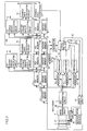
- Fig. 1 is a block diagram showing the whole structure of an automatic focusing apparatus in accordance with Embodiment 1 of the present invention.
- Fig. 2 is a graph showing relation between a focus evaluating value and a position of a focusing lens in the automatic focusing apparatus shown in Fig. 1.
- Fig. 3 is a block diagram showing the whole structure of an automatic focusing apparatus in accordance with Embodiment 2 of the present invention.
- Fig. 6 is a block diagram showing the whole structure of a conventional automatic focusing apparatus.
- Fig. 7 is a block diagram showing details of a focus evaluating value generating circuit of Fig. 6.
- Fig. 8 is a graph showing relation between the focus evaluating value and the position of the focusing lens in the automatic focusing apparatus shown in Fig. 6.
- Fig. 1 is a block diagram showing the whole structure of the automatic focusing apparatus in accordance with Embodiment 1 of the present invention.
- the automatic focusing apparatus includes a focusing lens 1, a focusing ring 2 for moving focusing lens 1 along the direction of the optical axis, a focusing motor 3 for rotating the focusing ring, and an image sensing circuit 4 including an image sensor such as a CCD (not shown) receiving incident light through focusing lens 1.
- an iris mechanism 21 for adjusting amount of light incident on the image sensor through focusing lens 1 is provided.
- image sensing circuit 4 In response to the incident light, image sensing circuit 4 generates a video signal.
- the automatic focusing apparatus further includes a focus evaluating value generating circuit 5 which detects high frequency component level of the video signal obtained from image sensing circuit 4, and integrates the high frequency component level every field to provide the result as a focus evaluating value (FEV).
- the video signal from the image sensing circuit 4 is also applied to a signal processing circuit (not shown), and the video signal processed therein is recorded on a magnetic tape, for example.
- the automatic focusing apparatus further includes a maximum value memory 6, an initial value memory 7, comparators 8 and 9, a motor position detector 30, a lens position memory 13, a comparator 14, a focusing motor control circuit 110 and a focusing motor driving circuit 131.
- a maximum value memory 6 an initial value memory 7, comparators 8 and 9, a motor position detector 30, a lens position memory 13, a comparator 14, a focusing motor control circuit 110 and a focusing motor driving circuit 131.
- the automatic focusing apparatus further includes a memory 11 and a comparator 12 and by these components, when the object changes after the end of focusing operation, automatic focusing operation by focusing motor control circuit 110 is resumed.
- focusing motor control circuit 110 and the focusing motor driving circuit 131 are further provided with new functions, which will be described later.
- the automatic focusing apparatus further includes four focus evaluating value memories 41 to 44. These four memories 41 to 44 respectively store focus evaluating values of 4 fields continuously supplied from focus evaluating value generating circuit 5.
- the automatic focusing apparatus further includes five position history memories 51 to 55. These five memories 51 to 55 respectively store position data of focusing lens 1 in 5 fields continuously supplied from motor position detector 30.
- the automatic focusing apparatus further includes an FEV change amount calculating circuit 61, a position change amount calculating circuit 63 and an FEV change rate calculating circuit 65.
- Calculating circuit 61 calculates the amount of change A1 of the focus evaluating value based on the focus evaluating value V1 stored in memory 41 and the focus evaluating value V3 stored in memory 43.
- Calculating circuit 63 calculates the amount of change V1 of lens 1 based on position data L1 stored in memory 52 and position data L3 stored in memory 54.
- Calculating circuit 65 calculates the rate of change R1 of the focus evaluating value based on the amounts of change A1 and B1 from calculating circuits 61 and 63.
- the automatic focusing apparatus further includes an FEV change amount calculating circuit 62, a position change amount calculating circuit 64 and an FEV change rate calculating circuit 66.
- Calculating circuit 62 calculates the amount of change A2 of the focus evaluating value based on the focus evaluating value V2 stored in memory 42 and the focus evaluating value V4 stored in memory 44.
- Calculating circuit 64 calculates the amount of change V2 of lens position based on position data L2 stored in memory 53 and position data L4 stored in memory 55.
- Calculating circuit 66 calculates the rate of change R2 of focus evaluating value based on the amounts of change A2 and B2 from calculating circuits 62 and 64.
- the automatic focusing apparatus further includes a change rate comparing circuit 67 for comparing rates of change R1 and R2 from calculating circuits 65 and 66.
- Focusing motor control circuit 110 is adapted such that it generates a speed control signal SC in response to the result of comparison from comparing circuit 67 and applies the signal to focusing motor driving circuit 131.
- Focusing motor driving circuit 131 is adapted to change the speed of rotation of focusing motor 3 in response to the speed control signal SC.
- memories 41 to 44 and 51 to 55, calculating circuits 61 to 66 and a comparing circuit 67 are newly added, and the conventional focusing motor control circuit 10 and focusing motor driving circuit 31 are improved.
- the focus evaluating value FEV from focus evaluating value generating circuit 5 is applied to comparators 8 and 9 as in the prior art example, and based on the focus evaluating value, focusing operation is carried out.
- the focus evaluating value FEV is also successively applied to focus evaluating value memory 41.
- focus evaluating value generating circuit 5 When focus evaluating value generating circuit 5 generates a focus evaluating value of a certain field, the focus evaluating value is first stored in memory 41. Thereafter, when focus evaluating value generating circuit 5 generates a focus evaluating value of the next field, the focus evaluating value V1 which has been stored in memory 41 is stored in memory 42, and the new focus evaluating value just generated from focus evaluating value generating circuit 5 is stored in memory 41.
- focus evaluating value generating circuit 5 When focus evaluating value generating circuit 5 generates a focus evaluating value of still another field, the focus evaluating value V2 which has been stored in memory 42 is stored in memory 43, and the focus evaluating value V1 which has been stored in memory 41 is stored in memory 42. The new focus evaluating value just generated from focus evaluating value generating circuit 5 is stored in memory 41.
- focus evaluating value generating circuit 5 When focus evaluating value generating circuit 5 generates a focus evaluating value of a still another field, the focus evaluating value V3 which has been stored in memory 43 is stored in memory 44, the focus evaluating value V2 which has been stored in memory 42 is stored in memory 43, and the focus evaluating value V1 which has been stored in memory 41 is stored in memory 42.
- the new focus evaluating value generated from focus evaluating value generating circuit 5 is stored in memory 41.
- the newest focus evaluating value V1 that is, the focus evaluating value of the current field is always stored in memory 41
- the focus evaluating value V2 of one field before is stored in memory 42
- the focus evaluating value V3 of two fields before is stored in memory 43
- the focus evaluating value V4 of three fields before is stored in memory 44.
- focus evaluating values of four fields that is, from the current field to the third last field are stored respectively.
- the focus evaluating value is generated successively field by field. Between respective fields, focusing lens 1 moves continuously. Accordingly, at an intermediate time point of each exposure time (1 field) of the image sensor, position of focusing motor 3 is detected by motor position detector 30, and the detected position is supplied as a representative lens position of each field to the position history memory 51. Therefore, in memory 51, the newest lens position data L0 is always stored.
- Data L0 stored in memory 51 is stored as lens position data L1 in position history memory 52 after 1 field.
- the data L1 stored in memory 52 is stored as lens position data L2 in position history memory 53 after another 1 field.
- Data L2 stored in memory 53 is stored as lens position data L3 in position history memory 54 after still another 1 field.
- Data L3 stored in memory 54 is stored as lens position data L4 in position history memory 55 after still another 1 field.
- the corresponding lens position data is stored at an intermediate time point in each field, while the corresponding focus evaluating value is stored in focus evaluating value memory 41 at the end of each field. This is because the focus evaluating value is an integration of the video signals successively applied every field.
- the focus evaluating value is supplied from focus evaluating value generating circuit 5 to focus evaluating value memory 41, the data L0 which has been stored in memory 51 is transferred to memory 52. Therefore, in memory 52, lens position data L1 corresponding to the focus evaluating value V1 stored in memory 41 is stored. In memory 53, lens position data L2 is stored, which corresponds to the focus evaluating value V2 stored in memory 42.
- lens position data L3 is stored which corresponds to the focus evaluating value V3 stored in memory 43.
- lens position data L4 is stored which corresponds to the focus evaluating value V4 stored in memory 44.
- lens position data L0 to L4 of 5 fields that is, from the current field to the fourth last field are stored respectively.
- the difference A1 corresponds to the amount of change of the focus evaluating value generated in 2 fields, that is, from the second last to the current field.
- the difference A2 corresponds to the amount of change of the focus evaluating value generated in 2 fields from three fields before to one field before the current field.
- the value B1 corresponds to the distance of movement of lens 1 during 2 fields, that is, the second last to the current field.
- the value B2 corresponds to the distance of movement of lens 1 during 2 fields, that is, the third last to the last field.
- the amount of change A1 of the focus evaluating value from calculating circuit 61 and the amount of change V1 of position from calculating circuit 63 are both applied to focus change rate calculating circuit 65, and in calculating circuit 65, the ratio A1/B1 of these amounts of change is calculated and applied as change rate R1 of focus evaluating value with respect to the amount of change of lens 1, to change rate comparing circuit 67.
- the ratio A1/B1 corresponds to the change rate of two fields, that is, from the second last to the current field.
- Focus evaluating value change amount A2 from calculating circuit 62 and position change amount B2 from calculating circuit 64 are both applied to focus change rate calculating circuit 66, and in calculating circuit 66, the ratio A2/B2 of the amounts of change is calculated and the result is applied to change rate comparing circuit 67 as the change rate R2 of the focus evaluating value with respect to the amount of change of the lens 1.
- the ratio A1/B2 corresponds to the change rate in 2 fields, that is, from three fields before to one field before.
- Fig. 2 is a graph showing relation between the focus evaluating value and the position of the focusing lens, and the relation between the change rate of the focus evaluating value and the position of the focusing lens.
- the solid line 100 represents the relation between the focus evaluating value and the position of the focusing lens
- the dotted line 101 represents the relation between the change rate of the focus evaluating value and the position of the focusing lens.
- the relation between the focus evaluating value and the position of the focusing lens is represented as a curve which assumes the maximum value at the in-focus position P.
- the relation between the change rate and the focusing lens position is represented as a curve which indicates the differential coefficient of the curve 100 of the focus evaluating value.
- the focusing lens 1 is at a near point considerably spaced apart to the object side from the in-focus position P. At this time, as it is considerably defocused, the focus evaluating value is nearly 0. From this near point to a point P1, the change rate of the focus evaluating value increases. From this point P1 to the in-focus position P, the change rate of the focus evaluating value decreases. By contrast, when the focusing lens 1 draws near to the in-focus position P from the infinite side, the change rate of the focus evaluating value from the infinite position to a position P2 increases, and from the point P2 to the in-focus position P, the change rate of the focus evaluating value decreases.
- the positions of scanning lines shift to some extent between the even and odd fields. Consequently, vertical positions in the picture differ slightly in adjacent fields. Namely, the focus evaluating value fluctuates in a period of 2 fields. Therefore, even if the amount of change of the focus evaluating value of 1 field is calculated, accurate rate of change of the focus evaluating value cannot be calculated based on the amount of change.
- Embodiment 1 two change rate calculating circuits 65 and 66 are provided as mentioned above, calculating circuit 65 calculating the change rate between odd fields while calculating circuit 66 calculating change rate of even fields. Therefore, the influence of fluctuation of the focus evaluating value generated in the period of 2 fields can be removed.
- Change rates R1 and R2 from change rate calculating circuits 65 an 66 are both applied to change rate comparing circuit 67 in which these rates R1 and R2 are compared with each other.
- R1 ⁇ R2 that is, when the change rate is increasing
- H (High) level comparison output is provided from comparing circuit 67.
- R1 ⁇ R2 that is, when change rate is decreasing
- L (Low) level comparison output is provided from comparing circuit 67.
- focusing motor control circuit 110 performs hill-climbing focusing operation based on the comparison output from comparators 8, 9 and 14, and changes the speed of driving focusing motor 3 based on the comparison output from change rate comparing circuit 67. In other wards, a function of controlling the speed of the motor is added to control circuit 110.
- focusing motor driving circuit 131 drives or stops focusing motor 3 or reverses the direction of rotation of the focusing motor in response to the output from focusing motor control circuit 111 which is based on the output from comparators 8, 9 and 14, and in addition, it switches the speed of driving the focusing motor 3 between two steps, that is, high speed and low speed, in response to the speed control signal SC from focusing motor control circuit 110 based on the output from comparing circuit 67. More specifically, a function of switching the speed of driving the focusing motor 3 in two steps in response to speed control signal SC is added to focusing motor driving circuit 131. When focusing motor 3 is driven at high speed, the amount of change of the focusing lens position per unit time increases when the focusing motor 3 is driven at low speed.
- the direction of initial movement of focusing lens 1 is determined by comparator 9. While lens 1 moves from the near point side to a point P1 near the in-focus point P, the change rate of the focus evaluating value increases, and therefore, an H level speed control signal SC is applied to the focusing motor driving circuit 131. Consequently, focusing motor 3 is driven at high speed, and lens 1 reaches the point P1 quickly.
- Focusing lens 1 passes through in-focus position P and reaches a position P' at which the focus evaluating value decreases from the maximum value by more than the threshold value M. However, since the speed of driving the focusing motor 3 is low, overrun of the focusing lens 1 can be suppressed.
- the speed of driving focusing motor 3 is switched from the high speed to the low speed when the focusing lens 1 reaches the position P2.
- Embodiment 1 since the speed of movement of focusing lens 1 is made lower when the change rate of the focusing evaluating value is decreasing than when the rate of the focusing evaluating value is increasing, focusing lens 1 can be moved quickly to the in-focus position P while overrun of the focusing lens 1 can be suppressed.
- focusing lens 1 can be accurately moved to the in-focus position P.
- Fig. 3 is a block diagram showing the whole structure of an automatic focusing apparatus in accordance with Embodiment 2 of the present invention.
- Embodiment 2 differs from Embodiment 1 above in that the change rate of the focus evaluating value is calculated based on the focus evaluating value of a certain field and the focus evaluating value of the next field, and the driving speed of the focusing motor 3 is changed based on the change rate.
- the automatic focusing apparatus includes a change amount calculating circuit 71 for calculating an amount of change of the focus evaluating value based on the focus evaluating values V1 and V2 stored in memories 41 and 42, a change amount calculating circuit 73 for calculating an amount of change of the lens position based on lens position data L1 and L2 stored in memories 52 and 53, and a change rate calculating circuit 75 for calculating the change rate of the focus evaluating value based on the amounts A3 and B3 of change from calculating circuits 71 and 73.
- the automatic focusing apparatus further includes a change amount calculating circuit 72 for calculating an amount of change of the focus evaluating value based on focus evaluating values V3 and V4 stored in memories 43 and 44, a change amount calculating circuit 74 for calculating an amount of change of lens position based on lens position data L3 and L4 stored in memories 54 and 55, and a change rate calculating circuit 76 for calculating rate of change of focus evaluating value based on these amounts A4 and B4 of change, from these calculating circuits 72 and 74.
- the automatic focusing apparatus further includes a change rate comparing circuit 77 for comparing the change rates R3 and R4 from change rate calculating circuits 75 and 76.
- the difference V1-V2 of the focus evaluating value V1 of the current field and the focus evaluating value V2 of the preceding field is calculated, and the result is applied as the amount of change A3 of the focus evaluating value to change rate calculating circuit 75.
- of the difference between lens position data L1 corresponding to the focus evaluating value V1 and lens position data L2 corresponding to the focus evaluating value V2 is calculated, and the result is applied as the amount of change B3 of the lens position to change rate calculating circuit 75.
- change rate calculating circuit 75 the ratio A3/B3 of the amounts of change A3 and B3 from calculating circuits 71 and 73 is calculated, and the result is applied to change rate comparing circuit 77 as change rate R3 of the focus evaluating value.
- the difference V3-V4 between the focus evaluating value V3 of the field preceding by two from the current field and the focus evaluating value V4 of the field preceding by three is calculated, and the result is applied as the amount of change A4 of the focus evaluating value to change rate calculating circuit 76.
- of the difference between lens position data L3 corresponding to the focus evaluating value V3 and lens position data L4 corresponding to focus evaluating value V4 is calculated, and the result is applied as the amount of change B4 of the lens position to change rate calculating circuit 76.
- change rate calculating circuit 76 the ratio A4/B4 of the amounts A4 and B4 of change from calculating circuits 72 and 74 is calculated, and the result is applied as the change rate R4 of the focus evaluating value to change rate comparing circuit 77.
- change rate comparing circuit 77 controls focusing motor control circuit 110 so that an H level speed control signal SC is generated.
- focusing motor driving circuit 131 drives the focusing motor 3 at high speed. Consequently, the amount of change of the lens position per unit time increases, and focusing lens moves quickly to the in-focus position.
- change rate comparing circuit 77 controls focusing motor control circuit 110 so that an L level speed control signal SC is generated.
- L level speed control signal SC In response to the L level speed control signal SC, focusing motor driving circuit 131 switches the speed of driving the focusing motor 3 from high speed to low speed. Consequently, the amount of change of the lens position per unit time decreases, and overrun of the lens near the in-focus position can be minimized.
- the change rate of the focus evaluating value between the current field and the last field is calculated, the change rate of the focus evaluating value between the second last and the third last fields is calculated, and these two calculated change rates are compared. Since there is time difference of 2 fields between these two change rates R3 and R4, fluctuation of the focus evaluating value of 2 field period caused by interlace scanning can be almost fully removed.
- the speed of driving focusing motor 3 cannot be controlled based on the comparison output from change rate comparing circuit 67 until at least 4 fields of time has passed. Therefore, it is preferred that the focusing motor driving circuit 131 is initially set to drive focusing motor 3 at high speed during these initial four fields. Alternatively, focusing motor driving circuit 131 may be initially set so that focusing motor 3 is driven at low speed.
- the speed of rotation of focusing motor 3 is switched in two steps. However, it may be switched in three steps. More specifically, in the vicinity of the near point, infinite point and points P1 and P2 at which change rate of the focus evaluating value hardly changes, focusing motor 3 may be rotated at an intermediate speed. Further, the speed of rotation of the focusing motor 3 may be changed continuously in response to the change rate of the focus evaluating value.
- the Embodiments 1 and 2 may be constituted by a microprocessor.
- the movement forward and rearward of focusing lens 1 may be implemented by a piezoelectric element instead of a motor. Further, not the focusing lens but the image sensor itself such as the CCD (not shown) may be moved forward or rearward.
- the front focus method in which the lens nearest to the object is moved as the focusing lens or a rear focus method in which the lens nearest to the image sensor is moved as the focusing lens, may be employed.
Landscapes
- Engineering & Computer Science (AREA)
- Multimedia (AREA)
- Signal Processing (AREA)
- Automatic Focus Adjustment (AREA)
Claims (5)
- Dispositif de mise au point automatique destiné à adapter automatiquement la mise au point par rapport à un objet en réponse à un signal vidéo obtenu à partir d'un moyen de capture d'image (1, 4) possédant un objectif et un capteur d'image recevant une lumière incidente à travers ledit objectif, comprenant :caractérisé en ce queun moyen de fourniture de valeur d'évaluation de la mise au point (5) destiné à délivrer un niveau de composante à haute fréquence du signal vidéo obtenu à partir dudit moyen de capture d'image en tant que valeur d'évaluation de la mise au point (FEV) à chaque première période prescrite, un moyen de variation de position relative de l'objectif (2, 3, 6, 7, 8, 9, 11, 12, 13, 14, 30, 110, 131) destiné à faire varier la position relative dudit objectif suivant une direction axiale par rapport audit capteur d'image, de sorte que la valeur d'évaluation de la mise au point provenant dudit moyen fournissant la valeur d'évaluation de la mise au point atteigne une valeur maximale,un moyen de calcul (51-55, 41-44, 61-66) destiné à calculer le rapport du niveau de variation (Al, A2) de la valeur d'évaluation de la mise au point dans une seconde période prescrite par rapport au niveau de variation (B1, B2) de la position dudit objectif correspondant à celui-ci, et à fournir le rapport sous la forme d'un taux de variation de la valeur d'évaluation (R1, R2), etun moyen de commande de vitesse (67, 110, 131) répondant au taux de variation de la valeur d'évaluation provenant dudit moyen de calcul pour commander la vitesse de variation de ladite position relative de l'objectif grâce audit moyen de variation de la position relative de l'objectif,dans lequel ledit moyen de commande de vitesse comporteun moyen de détection d'augmentation et de diminution (67) destiné à détecter si le taux de variation de la valeur d'évaluation fourni successivement à partir dudit moyen de calcul augmente ou diminue, etun moyen (110, 131) sensible à la sortie provenant dudit moyen de détection d'augmentation et de diminution, destiné à rendre la vitesse de variation de ladite position relative de l'objectif grâce audit moyen de variation de la position relative de l'objectif plus faible lorsque le taux de variation de la valeur d'évaluation diminue que lorsque le taux de variation de la valeur d'évaluation augmente,ledit moyen destiné à fournir une valeur d'évaluation de la mise au point, intègre le niveau de la composante à haute fréquence à chaque balayage de trame et délivre le résultat de l'intégration sous la forme d'une valeur d'évaluation de la mise au point, etledit moyen de calcul calcule le rapport du niveau de variation de la valeur d'évaluation de la mise au point depuis un certain balayage de trame jusqu'à un second balayage de trame suivant par rapport au niveau de variation de ladite position relative de l'objectif correspondant à celui-ci, et fournit le rapport en tant que taux de variation de la valeur d'évaluation.
- Dispositif de mise au point automatique selon la revendication 1, dans lequelledit moyen de calcul comprendun moyen de mémorisation de valeurs d'évaluation (41-44) destiné à mémoriser des valeurs d'évaluation de la mise au point de quatre balayages de trame fournies de façon continue à partir dudit moyen fournissant la valeur d'évaluation de la mise au point,un moyen de mémorisation de la position de l'objectif (52-55) destiné à mémoriser quatre données de position dudit objectif correspondant à quatre valeurs d'évaluation de la mise au point mémorisées dans ledit moyen de mémorisation de valeurs d'évaluation,un premier moyen de calcul de taux de variation (62, 64, 66), destiné au calcul basé sur la première et la troisième (V4, V2) des quatre valeurs d'évaluation de la mise au point, mémorisées dans ledit moyen de mémorisation des valeurs d'évaluation, et sur les première et troisième (L4, L2) correspondantes des quatre données de position mémorisées dans ledit moyen de mémorisation des positions de l'objectif, le rapport du niveau de variation (A2) des valeurs d'évaluation de la mise au point par rapport au niveau de variation (B2) de ces positions, et à fournir le rapport en tant que premier taux de variation de la valeur d'évaluation (R2), etun second moyen de calcul de taux de variation (61, 63, 65), destiné au calcul basé sur la deuxième et la quatrième (V3, V1) des quatre valeurs d'évaluation de la mise au point mémorisées dans ledit moyen de mémorisation des valeurs d'évaluation, et sur les deuxième et quatrième (L3, L1) correspondantes des quatre données de position mémorisées dans ledit moyen de mémorisation des positions de l'objectif, le rapport du niveau de variation (A1) des valeurs d'évaluation de la mise au point par rapport au niveau de variation (B1) de ces positions, et à fournir le rapport en tant que second taux de variation des valeurs d'évaluation (R1),ledit moyen de détection d'augmentation et de diminution comprend un moyen de comparaison (67) destiné à comparer le premier taux de variation de la valeur d'évaluation provenant dudit premier moyen de calcul du taux de variation, avec le second taux d'évaluation de la valeur d'évaluation provenant dudit second moyen de calcul du taux de variation, et à indiquer que le taux de variation de la valeur d'évaluation de la mise au point augmente lorsque le premier taux de variation de la valeur d'évaluation est plus faible que le second taux de variation de la valeur d'évaluation, et indiquer sinon que le taux de variation de la valeur d'évaluation de la mise au point diminue.
- Dispositif de mise au point automatique selon la revendication 1, dans lequelledit moyen de calcul comprendune première mémoire de la valeur d'évaluation (41) destinée à mémoriser successivement une valeur d'évaluation de la mise au point de chaque balayage de trame successivement fournie à partir dudit moyen destiné à fournir une valeur d'évaluation de la mise au point,une seconde mémoire de la valeur d'évaluation (42) destinée à mémoriser, au lieu de ladite première mémoire de valeur d'évaluation, la valeur d'évaluation de la mise au point qui a été mémorisée dans ladite première mémoire de valeur d'évaluation, lorsque ledit moyen destiné à fournir la valeur d'évaluation de la mise au point fournit une valeur d'évaluation de la mise au point correspondant à un balayage de trame suivant,une troisième mémoire de la valeur d'évaluation (43) destinée à mémoriser, au lieu de ladite seconde mémoire de valeur d'évaluation, la valeur d'évaluation de la mise au point qui a été mémorisée dans ladite seconde mémoire de valeur d'évaluation, lorsque ledit moyen destiné à fournir la valeur d'évaluation de la mise au point fournit une valeur d'évaluation de la mise au point correspondant au balayage de trame suivant,une quatrième mémoire de la valeur d'évaluation (44) destinée à mémoriser, au lieu de ladite troisième mémoire de valeur d'évaluation, la valeur d'évaluation de la mise au point qui a été mémorisée dans ladite troisième mémoire de valeur d'évaluation, lorsque ledit moyen destiné à fournir la valeur d'évaluation de la mise au point fournit une valeur d'évaluation de la mise au point correspondant au balayage de trame suivant,une première mémoire de position (52) destinée à mémoriser des données de position dudit objectif correspondant à la valeur d'évaluation de la mise au point mémorisée dans ladite première mémoire de valeur d'évaluation,une seconde mémoire de position (53) destinée à mémoriser, au lieu de ladite première mémoire de position, les données de position qui ont été mémorisées dans ladite première mémoire de position, lorsque ledit moyen destiné à fournir la valeur d'évaluation de la mise au point fournit une valeur d'évaluation de la mise au point correspondant à un balayage de trame suivant,une troisième mémoire de position (54) destinée à mémoriser, au lieu de ladite seconde mémoire de position, les données de position qui ont été mémorisées dans ladite seconde mémoire de position, lorsque ledit moyen destiné à fournir la valeur d'évaluation de la mise au point fournit une valeur d'évaluation de la mise au point correspondant au balayage de trame suivant,une quatrième mémoire de position (55) destinée à mémoriser, au lieu de ladite troisième mémoire de position, les données de position qui ont été mémorisées dans ladite troisième mémoire de position, lorsque ledit moyen destiné à fournir la valeur d'évaluation de la mise au point fournit une valeur d'évaluation de la mise au point correspondant au balayage de trame suivant,un premier moyen de calcul du niveau de variation de la valeur d'évaluation (62) destiné à calculer la différence entre la valeur d'évaluation de la mise au point mémorisée dans ladite seconde mémoire de valeur d'évaluation et la valeur d'évaluation de la mise au point mémorisée dans ladite quatrième mémoire de valeur d'évaluation, et fournissant la différence en tant que premier niveau de variation de la valeur d'évaluation (A2),un premier moyen de calcul du niveau de variation de la valeur d'évaluation (64) destiné à calculer la différence entre les données de position mémorisées dans ladite seconde mémoire de position et les données de position mémorisées dans ladite quatrième mémoire de position afin de fournir la différence en tant que premier niveau de variation de position (B2),un premier moyen de calcul du taux de variation de la valeur d'évaluation (66) destiné à calculer le rapport du premier niveau de variation de la valeur d'évaluation provenant dudit premier moyen de calcul du niveau de variation de la valeur d'évaluation par rapport au premier niveau de variation de position provenant dudit premier moyen de calcul du niveau de variation de la position, et à fournir le rapport en tant que premier taux de variation de la valeur d'évaluation (R2),un second moyen de calcul du niveau de variation de la valeur d'évaluation (61) destiné à calculer la différence entre la valeur d'évaluation de la mise au point mémorisée dans ladite première mémoire de valeur d'évaluation et la valeur d'évaluation de la mise au point mémorisée dans ladite troisième mémoire de valeur d'évaluation et à fournir la différence en tant que second niveau de variation de la valeur d'évaluation (A1),un second moyen de calcul du niveau de variation de la position (63) destiné à calculer la différence entre les données de position mémorisées dans ladite première mémoire de position et les données de position mémorisées dans ladite troisième mémoire de position, et à fournir la différence en tant que second niveau de variation de position (B1), etun second moyen de calcul du taux de variation de la valeur d'évaluation (65) afin de calculer le rapport dudit second niveau de variation de la valeur d'évaluation provenant dudit second moyen de calcul de niveau de variation de la valeur d'évaluation par rapport au second niveau de variation de position provenant dudit second moyen de calcul du niveau de variation de la position et à fournir le rapport en tant que second taux de variation de la valeur d'évaluation (R1), etledit moyen de détection d'augmentation et de diminution comprend un moyen de comparaison (67) destiné à comparer le premier taux de variation de la valeur d'évaluation provenant dudit premier moyen de calcul du taux de variation de la valeur d'évaluation avec le second taux de variation de la valeur d'évaluation provenant dudit second moyen de calcul du taux de variation de la valeur d'évaluation et à indiquer que le taux de variation de la valeur d'évaluation de la mise au point augmente lorsque le premier taux de variation de la valeur d'évaluation est plus faible que le second taux de variation de la valeur d'évaluation, et indiquant sinon que le taux de variation de la valeur d'évaluation de la mise au point diminue.
- Dispositif de mise au point automatique destiné à associer automatiquement la mise au point par rapport à un objet en réponse à un signal vidéo obtenu à partir d'un moyen de capture d'image (1, 4) possédant un objectif et un capteur d'image recevant une lumière incidente à travers ledit objectif, comprenant :caractérisé en ce queun moyen de fourniture de valeur d'évaluation de la mise au point (5) destiné à délivrer un niveau de composante à haute fréquence du signal vidéo obtenu à partir dudit moyen de capture d'image en tant que valeur d'évaluation de la mise au point (FEV) au niveau de chaque première période prescrite,un moyen de variation de la position relative de l'objectif (2, 3, 6, 7, 8, 9, 11, 12, 13, 14, 30, 110, 131) destiné à faire varier la position relative dudit objectif suivant une direction axiale par rapport audit capteur d'image, de sorte que la valeur d'évaluation de la mise au point provenant dudit moyen fournissant la valeur d'évaluation de la mise au point atteigne une valeur maximale,un moyen de calcul (51-55, 41-44, 61-66) destiné à calculer le rapport du niveau de variation (A1, A2) de la valeur d'évaluation de la mise au point dans une seconde période prescrite par rapport au niveau de variation (B1, B2) de la position dudit objectif correspondant à celui-ci, et à fournir le rapport sous la forme d'un taux de variation de la valeur d'évaluation (R1, R2), etun moyen de commande de vitesse (67, 110, 131) répondant au taux de variation de la valeur d'évaluation provenant dudit moyen de calcul afin de commander la vitesse de variation de ladite position relative de l'objectif grâce audit moyen de variation de la position relative de l'objectif,dans lequel, ledit moyen de commande de vitesse comporteun moyen de détection d'augmentation et de diminution (67) destiné à détecter si le taux de variation de la valeur d'évaluation fourni successivement à partir dudit moyen de calcul, augmente ou diminue, etun moyen (110, 131) sensible à la sortie provenant dudit moyen de détection d'augmentation et de diminution, destiné à rendre la vitesse de variation de ladite position relative de l'objectif grâce audit moyen de variation de la position relative de l'objectif plus faible lorsque le taux de variation de la valeur d'évaluation diminue que lorsque le taux de variation de la valeur d'évaluation augmente,ledit moyen destiné à fournir une valeur d'évaluation de la mise au point, intègre le niveau de la composante à haute fréquence à chaque balayage de trame et délivre le résultat de l'intégration sous la forme d'une valeur d'évaluation de la mise au point, etledit moyen de calcul comprendun moyen de mémorisation de valeurs d'évaluation (41-44) destiné à mémoriser des valeurs d'évaluation de la mise au point de quatre balayages de trame fournies de façon continue à partir dudit moyen fournissant la valeur d'évaluation de la mise au point,un moyen de mémorisation de la position de l'objectif (52-55) destiné à mémoriser quatre données de position dudit objectif correspondant aux quatre valeurs d'évaluation de la mise au point, mémorisées dans ledit moyen de mémorisation de valeurs d'évaluation,un premier moyen de calcul du taux de variation (72, 74, 76), destiné au calcul, basé sur les deux valeurs précédentes (V4, V2) des quatre valeurs d'évaluation de la mise au point, mémorisées dans ledit moyen de mémorisation des valeurs d'évaluation, et sur les deux valeurs précédentes correspondantes (L4, L3) des quatre données de position mémorisées dans ledit moyen de mémorisation des positions de l'objectif, du rapport du niveau de variation (A4) des valeurs d'évaluation de la mise au point par rapport au niveau de variation (B4) de ces positions, et à fournir le rapport en tant que premier taux de variation de la valeur d'évaluation (R4), etun second moyen de calcul du taux de variation (71, 73, 75), destiné au calcul, basé sur deux valeurs suivantes (V2, V1) des quatre valeurs d'évaluation de la mise au point mémorisées dans ledit moyen de mémorisation des valeurs d'évaluation, et les deux valeurs suivantes correspondantes (L2, L1) des quatre données de position mémorisées dans ledit moyen de mémorisation des positions de l'objectif, du rapport du niveau de variation (A3) des valeurs d'évaluation de la mise au point par rapport au niveau de variation (B3) de ces positions, et à fournir le second taux de variation de la valeur d'évaluation (R3), etledit moyen de détection d'augmentation et de diminution, comprend un moyen de comparaison (77) destiné à comparer le premier taux de variation de la valeur d'évaluation provenant dudit premier moyen de calcul du taux de variation, avec le second taux de variation de la valeur d'évaluation provenant dudit second moyen de calcul du taux de variation, et à indiquer que le taux de variation de la valeur d'évaluation de la mise au point augmente lorsque le premier taux de variation de la valeur d'évaluation est plus faible que le second taux de variation de la valeur d'évaluation, et indiquant sinon que le taux de variation de la valeur d'évaluation de la mise au point diminue.
- Dispositif de mise au point automatique selon la revendication 4, dans lequelledit moyen de calcul comprendune première mémoire de la valeur d'évaluation (41) destinée à mémoriser successivement la valeur d'évaluation de la mise au point de chaque balayage de trame fournie successivement à partir dudit moyen fournissant la valeur d'évaluation de la mise au point,une seconde mémoire de la valeur d'évaluation (42) destinée à mémoriser, au lieu de ladite première mémoire de valeur d'évaluation, la valeur d'évaluation de la mise au point qui a été mémorisée dans ladite première mémoire de valeur d'évaluation, lorsque ledit moyen fournissant la valeur d'évaluation de la mise au point fournit une valeur d'évaluation de la mise au point d'un balayage de trame suivant,une troisième mémoire de la valeur d'évaluation (43) destinée à mémoriser, au lieu de ladite seconde mémoire de valeur d'évaluation, la valeur d'évaluation de la mise au point qui a été mémorisée dans ladite seconde mémoire de valeur d'évaluation, lorsque ledit moyen fournissant la valeur d'évaluation de la mise au point délivre une valeur d'évaluation de la mise au point correspondant au balayage de trame suivant,une quatrième mémoire de la valeur d'évaluation (44) destinée à mémoriser, au lieu de ladite troisième mémoire de valeur d'évaluation, la valeur d'évaluation de la mise au point qui a été mémorisée dans ladite troisième mémoire de valeur d'évaluation, lorsque ledit moyen fournissant la valeur d'évaluation de la mise au point délivre une valeur d'évaluation de la mise au point du balayage de trame suivant,une première mémoire de position (52) destinée à mémoriser des données de position dudit objectif correspondant à la valeur d'évaluation de la mise au point mémorisée dans ladite première mémoire de valeur d'évaluation,une seconde mémoire de position (53) destinée à mémoriser, au lieu de ladite première mémoire de position, les données de position qui ont été mémorisées dans ladite première mémoire de position, lorsque ledit moyen fournissant la valeur d'évaluation de la mise au point délivre une valeur d'évaluation de la mise au point du balayage de trame suivant,une troisième mémoire de position (54) destinée à mémoriser, au lieu de ladite seconde mémoire de position, les données de position qui ont été mémorisées dans ladite seconde mémoire de position, lorsque ledit moyen fournissant la valeur d'évaluation de la mise au point délivre une valeur d'évaluation de la mise au point du balayage de trame suivant,une quatrième mémoire de position (55) destinée à mémoriser, au lieu de ladite troisième mémoire de position, les données de position qui ont été mémorisées dans ladite troisième mémoire de position, lorsque ledit moyen fournissant la valeur d'évaluation de la mise au point délivre une valeur d'évaluation de la mise au point du balayage de trame suivant,un premier moyen de calcul du niveau de variation de la valeur d'évaluation (72) destiné à calculer la différence entre la valeur d'évaluation de la mise au point mémorisée dans ladite quatrième mémoire de valeur d'évaluation et la valeur d'évaluation de la mise au point mémorisée dans ladite troisième mémoire de valeur d'évaluation, et à délivrer la différence en tant que premier niveau de variation de la valeur d'évaluation (A4),un premier moyen de calcul du niveau de variation de la position (74) destiné à calculer la différence entre les données de position mémorisées dans ladite quatrième mémoire de position et les données de position mémorisées dans ladite troisième mémoire de position et à délivrer la différence en tant que premier niveau de variation de la position (B4),un premier moyen de calcul du taux de variation de la valeur d'évaluation (76) destiné à calculer le rapport dudit premier niveau de variation de la valeur d'évaluation provenant dudit premier moyen de calcul du niveau de variation de la valeur d'évaluation par rapport à un premier niveau de variation de position provenant dudit premier moyen de calcul du niveau de variation de la position, et à délivrer le rapport en tant que premier taux de variation de la valeur d'évaluation (R4),un second moyen de calcul de niveau de variation de la valeur d'évaluation (72) destiné à calculer la différence entre la valeur d'évaluation de la mise au point mémorisée dans ladite seconde mémoire de valeur d'évaluation et la valeur d'évaluation de la mise au point mémorisée dans ladite première mémoire de valeur d'évaluation et à délivrer la différence en tant que second niveau de variation de la valeur d'évaluation (A3),un second moyen de calcul de niveau de variation de la position (73) destiné à calculer la différence entre les données de position mémorisées dans ladite seconde mémoire de position et les données de position mémorisées dans ladite première mémoire de position, et à délivrer la différence en tant que second niveau de variation de la position (B3), etun second moyen de calcul du taux de variation de la valeur d'évaluation (75) destiné à calculer le rapport du second niveau de variation de la valeur d'évaluation provenant dudit second moyen de calcul de niveau de variation de la valeur d'évaluation par rapport au second niveau de variation de la position provenant dudit second moyen de calcul du niveau de variation de la position et à délivrer le rapport en tant que second taux de variation de la valeur d'évaluation (R3), etledit moyen de détection d'augmentation et de diminution comprend un moyen de comparaison (77) destiné à comparer le premier taux de variation de la valeur d'évaluation provenant dudit premier moyen de calcul du taux de variation de la valeur d'évaluation avec le second taux de variation de la valeur d'évaluation provenant dudit second moyen de calcul du taux de variation de la valeur d'évaluation et à indiquer que le taux de variation de la valeur d'évaluation de la mise au point augmente lorsque le premier taux de variation de la valeur d'évaluation est plus faible que le second taux de variation de la valeur d'évaluation, et indiquant sinon que le taux de variation de la valeur d'évaluation de la mise au point diminue.
Applications Claiming Priority (4)
| Application Number | Priority Date | Filing Date | Title |
|---|---|---|---|
| JP146286/93 | 1993-06-17 | ||
| JP5146286A JP2919706B2 (ja) | 1993-06-17 | 1993-06-17 | オートフォーカスカメラ |
| JP153663/93 | 1993-06-24 | ||
| JP5153663A JPH0715648A (ja) | 1993-06-24 | 1993-06-24 | オートフォーカスビデオカメラ |
Publications (2)
| Publication Number | Publication Date |
|---|---|
| EP0630153A1 EP0630153A1 (fr) | 1994-12-21 |
| EP0630153B1 true EP0630153B1 (fr) | 1999-01-20 |
Family
ID=26477181
Family Applications (1)
| Application Number | Title | Priority Date | Filing Date |
|---|---|---|---|
| EP94109396A Expired - Lifetime EP0630153B1 (fr) | 1993-06-17 | 1994-06-17 | Dispositif de focalisation automatique pour associer automatiquement la focalisation en fonction du signal vidéo |
Country Status (4)
| Country | Link |
|---|---|
| US (2) | US5757429A (fr) |
| EP (1) | EP0630153B1 (fr) |
| KR (1) | KR100275185B1 (fr) |
| DE (1) | DE69416039T2 (fr) |
Families Citing this family (26)
| Publication number | Priority date | Publication date | Assignee | Title |
|---|---|---|---|---|
| JPH09168113A (ja) * | 1995-06-05 | 1997-06-24 | Sony Corp | オートフォーカス装置 |
| JPH0933791A (ja) * | 1995-07-21 | 1997-02-07 | Sony Corp | レンズ駆動装置及び撮像装置 |
| US6362852B2 (en) * | 1996-01-11 | 2002-03-26 | Sony Corporation | Focus control apparatus and method for use with a video camera or the like |
| JPH11258484A (ja) * | 1998-03-09 | 1999-09-24 | Sanyo Electric Co Ltd | オートフォーカスカメラ |
| JP4090276B2 (ja) * | 2002-05-28 | 2008-05-28 | 富士フイルム株式会社 | デジタルカメラ |
| US20040036792A1 (en) * | 2002-08-23 | 2004-02-26 | Chikatsu Moriya | Camera system and focus information display apparatus |
| US7345706B2 (en) * | 2002-08-23 | 2008-03-18 | Fuji Photo Optical Co., Ltd. | Auto focus system |
| JP4235474B2 (ja) * | 2003-03-20 | 2009-03-11 | キヤノン株式会社 | 撮像装置 |
| JP4407379B2 (ja) * | 2004-05-21 | 2010-02-03 | 株式会社ニコン | 電子カメラおよび画像処理システム |
| EP1679546B1 (fr) * | 2005-01-07 | 2014-12-24 | Canon Kabushiki Kaisha | Procédé et appareil de mise au point |
| JP4557869B2 (ja) * | 2005-11-18 | 2010-10-06 | 株式会社日立製作所 | 光ディスク種別判別方法、光ディスク装置 |
| JP5247044B2 (ja) * | 2007-02-16 | 2013-07-24 | キヤノン株式会社 | 撮像装置 |
| US7809258B2 (en) * | 2007-07-06 | 2010-10-05 | Flir Systems Ab | Camera and method for use with camera |
| JPWO2009113326A1 (ja) * | 2008-03-11 | 2011-07-21 | 三洋電機株式会社 | 撮像装置 |
| JP4535173B2 (ja) * | 2008-06-26 | 2010-09-01 | ソニー株式会社 | 撮像装置及びフォーカス制御方法並びにプログラム |
| WO2010050200A1 (fr) * | 2008-10-30 | 2010-05-06 | パナソニック株式会社 | Système d'appareil photo |
| JP5292175B2 (ja) * | 2009-05-15 | 2013-09-18 | 株式会社エルモ社 | 撮像装置、焦点調節方法 |
| KR101085925B1 (ko) * | 2010-03-23 | 2011-11-23 | 삼성전자주식회사 | 복수개의 밴드패스필터를 이용하여 자동초점 조절 기능을 수행하는 촬영장치 및 이에 적용되는 자동초점 조절방법 |
| TWI459113B (zh) * | 2012-03-19 | 2014-11-01 | Altek Corp | 攝像裝置及其鏡頭致動裝置及鏡頭致動方法 |
| JP5750671B1 (ja) * | 2013-07-29 | 2015-07-22 | オリンパス株式会社 | 撮像装置 |
| US8879858B1 (en) | 2013-10-01 | 2014-11-04 | Gopro, Inc. | Multi-channel bit packing engine |
| US9288379B2 (en) * | 2014-03-12 | 2016-03-15 | Omnivision Technologies, Inc. | System and method for continuous auto focus within camera module |
| US9762789B2 (en) | 2015-01-28 | 2017-09-12 | Panasonic Intellectual Property Management Co., Ltd. | Autofocus device, imaging device, and autofocus method |
| CN108369326B (zh) | 2015-12-22 | 2019-07-09 | 富士胶片株式会社 | 摄像装置、对焦控制方法及对焦控制程序 |
| CN110392200B (zh) | 2018-04-20 | 2021-01-26 | 杭州海康威视数字技术股份有限公司 | 自动聚焦的方法和装置 |
| CN110769230B (zh) * | 2019-08-02 | 2021-09-28 | 成都极米科技股份有限公司 | 一种对焦方法、装置及投影设备 |
Family Cites Families (17)
| Publication number | Priority date | Publication date | Assignee | Title |
|---|---|---|---|---|
| US4531158A (en) * | 1982-01-27 | 1985-07-23 | Hitachi, Ltd. | Automatic focusing system for video cameras |
| US4762986A (en) * | 1986-03-10 | 1988-08-09 | Canon Kabushiki Kaisha | Automatic focussing system including in-focus position prediction means |
| US4841370A (en) * | 1986-11-17 | 1989-06-20 | Sanyo Electric Co., Ltd. | Automatic focusing circuit for automatically matching focus in response to video signal |
| JPH0644806B2 (ja) * | 1987-02-18 | 1994-06-08 | 三洋電機株式会社 | オ−トフオ−カス回路 |
| US4922346A (en) * | 1987-06-30 | 1990-05-01 | Sanyo Electric Co., Ltd. | Automatic focusing apparatus having a variable focusing speed and particularly suited for use with interlaced scanning |
| US5005086A (en) * | 1988-03-04 | 1991-04-02 | Sony Corporation | Focus control apparatus having two focusing speeds |
| US4920369A (en) * | 1988-05-06 | 1990-04-24 | Canon Kabushiki Kaisha | Lens position control device |
| DE68914712T2 (de) * | 1988-05-11 | 1994-10-13 | Sanyo Electric Co | Bildsensorapparat mit einer automatischen Fokussiereinrichtung für automatische Fokusanpassung in Abhängigkeit von Videosignalen. |
| JPH0293509A (ja) * | 1988-09-30 | 1990-04-04 | Toshiba Corp | 自動焦点合せ装置 |
| US4920420A (en) * | 1988-11-10 | 1990-04-24 | Hitachi, Ltd. | Automatic focusing system |
| JPH0313073A (ja) * | 1989-06-09 | 1991-01-22 | Canon Inc | 自動焦点調節装置 |
| JP2728943B2 (ja) * | 1989-07-08 | 1998-03-18 | キヤノン株式会社 | レンズ制御装置 |
| US5249058A (en) * | 1989-08-08 | 1993-09-28 | Sanyo Electric Co., Ltd. | Apparatus for automatically focusing a camera lens |
| JP2974339B2 (ja) * | 1989-09-20 | 1999-11-10 | キヤノン株式会社 | 自動焦点調節装置 |
| US5200828A (en) * | 1990-03-19 | 1993-04-06 | Sam Jung Co., Ltd. | Autofocusing device for use in a video camera and an autofocusing method thereof |
| US5287223A (en) * | 1990-05-10 | 1994-02-15 | Canon Kabushiki Kaisha | Lens drive controlling apparatus |
| US5432332A (en) * | 1992-04-28 | 1995-07-11 | Fuji Photo Optical Co., Ltd. | Method of auto-focussing and system therefor |
-
1994
- 1994-06-16 KR KR1019940013596A patent/KR100275185B1/ko not_active Expired - Fee Related
- 1994-06-16 US US08/260,768 patent/US5757429A/en not_active Expired - Lifetime
- 1994-06-17 EP EP94109396A patent/EP0630153B1/fr not_active Expired - Lifetime
- 1994-06-17 DE DE69416039T patent/DE69416039T2/de not_active Expired - Lifetime
-
1995
- 1995-06-02 US US08/459,478 patent/US5574502A/en not_active Expired - Lifetime
Also Published As
| Publication number | Publication date |
|---|---|
| US5757429A (en) | 1998-05-26 |
| DE69416039D1 (de) | 1999-03-04 |
| US5574502A (en) | 1996-11-12 |
| KR950002407A (ko) | 1995-01-04 |
| EP0630153A1 (fr) | 1994-12-21 |
| KR100275185B1 (ko) | 2000-12-15 |
| DE69416039T2 (de) | 1999-09-02 |
Similar Documents
| Publication | Publication Date | Title |
|---|---|---|
| US5757429A (en) | Automatic focusing apparatus which adjusts the speed of focusing based on a change in the rate of the focus evaluating value | |
| EP0297587B1 (fr) | Circuit de localisation automatique pour associer automatiquement la localisation en fonction du signal vidéo | |
| US6236431B1 (en) | Video camera apparatus with distance measurement area adjusted based on electronic magnification | |
| KR100221518B1 (ko) | 영상 신호에 기초하여 촛점의 자동 정합을 행하는 오토 포커스 장치 | |
| AU603618B2 (en) | An automatic focusing circuit | |
| US7515200B2 (en) | Image sensing apparatus, focus adjustment method, and focus adjustment computer control program | |
| EP1895768B1 (fr) | Appareil de réglage de mise au point, appareil de capture d'image, et procédé de contrôle | |
| US7969502B2 (en) | Focus adjusting apparatus and focus adjusting method | |
| JP3296687B2 (ja) | オートフォーカスビデオカメラ | |
| US5402175A (en) | Automatic focusing device wherein lens movement is controlled in accordance with lens hunting | |
| JPH077650A (ja) | オートフォーカスビデオカメラ | |
| US20050083428A1 (en) | Image pickup apparatus | |
| US5296970A (en) | Zoom lens system | |
| US5699116A (en) | Camera apparatus | |
| JP3513180B2 (ja) | 撮像装置 | |
| JP3689497B2 (ja) | 自動焦点調節方法及び装置 | |
| JP3380627B2 (ja) | オートフォーカス装置 | |
| KR970004183B1 (ko) | 비디오 카메라의 화면 처리 방법 | |
| JP4510193B2 (ja) | 焦点調節装置及び焦点調節方法 | |
| JP2709491B2 (ja) | 自動焦点調節装置 | |
| JPH1051679A (ja) | 自動焦点調節方法及び装置並びに記憶媒体 | |
| JPH0698240A (ja) | ビデオカメラのオートフォーカス装置 | |
| JP3244884B2 (ja) | 焦点検出装置 | |
| JPH07112253B2 (ja) | オートフオーカスビデオカメラ |
Legal Events
| Date | Code | Title | Description |
|---|---|---|---|
| PUAI | Public reference made under article 153(3) epc to a published international application that has entered the european phase |
Free format text: ORIGINAL CODE: 0009012 |
|
| AK | Designated contracting states |
Kind code of ref document: A1 Designated state(s): DE FR GB |
|
| 17P | Request for examination filed |
Effective date: 19950621 |
|
| 17Q | First examination report despatched |
Effective date: 19970829 |
|
| GRAG | Despatch of communication of intention to grant |
Free format text: ORIGINAL CODE: EPIDOS AGRA |
|
| GRAG | Despatch of communication of intention to grant |
Free format text: ORIGINAL CODE: EPIDOS AGRA |
|
| GRAH | Despatch of communication of intention to grant a patent |
Free format text: ORIGINAL CODE: EPIDOS IGRA |
|
| GRAH | Despatch of communication of intention to grant a patent |
Free format text: ORIGINAL CODE: EPIDOS IGRA |
|
| GRAA | (expected) grant |
Free format text: ORIGINAL CODE: 0009210 |
|
| AK | Designated contracting states |
Kind code of ref document: B1 Designated state(s): DE FR GB |
|
| PG25 | Lapsed in a contracting state [announced via postgrant information from national office to epo] |
Ref country code: FR Free format text: LAPSE BECAUSE OF FAILURE TO SUBMIT A TRANSLATION OF THE DESCRIPTION OR TO PAY THE FEE WITHIN THE PRESCRIBED TIME-LIMIT Effective date: 19990120 |
|
| REF | Corresponds to: |
Ref document number: 69416039 Country of ref document: DE Date of ref document: 19990304 |
|
| PG25 | Lapsed in a contracting state [announced via postgrant information from national office to epo] |
Ref country code: DE Free format text: LAPSE BECAUSE OF FAILURE TO SUBMIT A TRANSLATION OF THE DESCRIPTION OR TO PAY THE FEE WITHIN THE PRESCRIBED TIME-LIMIT Effective date: 19990421 |
|
| EN | Fr: translation not filed | ||
| PLBE | No opposition filed within time limit |
Free format text: ORIGINAL CODE: 0009261 |
|
| STAA | Information on the status of an ep patent application or granted ep patent |
Free format text: STATUS: NO OPPOSITION FILED WITHIN TIME LIMIT |
|
| 26N | No opposition filed | ||
| REG | Reference to a national code |
Ref country code: GB Ref legal event code: IF02 |
|
| PGFP | Annual fee paid to national office [announced via postgrant information from national office to epo] |
Ref country code: DE Payment date: 20120613 Year of fee payment: 19 |
|
| PGFP | Annual fee paid to national office [announced via postgrant information from national office to epo] |
Ref country code: GB Payment date: 20120613 Year of fee payment: 19 |
|
| GBPC | Gb: european patent ceased through non-payment of renewal fee |
Effective date: 20130617 |
|
| REG | Reference to a national code |
Ref country code: DE Ref legal event code: R119 Ref document number: 69416039 Country of ref document: DE Effective date: 20140101 |
|
| PG25 | Lapsed in a contracting state [announced via postgrant information from national office to epo] |
Ref country code: DE Free format text: LAPSE BECAUSE OF NON-PAYMENT OF DUE FEES Effective date: 20140101 Ref country code: GB Free format text: LAPSE BECAUSE OF NON-PAYMENT OF DUE FEES Effective date: 20130617 |