EP0630213B1 - Ensemble trocart a pointe retractable - Google Patents
Ensemble trocart a pointe retractable Download PDFInfo
- Publication number
- EP0630213B1 EP0630213B1 EP93907059A EP93907059A EP0630213B1 EP 0630213 B1 EP0630213 B1 EP 0630213B1 EP 93907059 A EP93907059 A EP 93907059A EP 93907059 A EP93907059 A EP 93907059A EP 0630213 B1 EP0630213 B1 EP 0630213B1
- Authority
- EP
- European Patent Office
- Prior art keywords
- trocar
- tip
- piercing tip
- retracting
- links
- Prior art date
- Legal status (The legal status is an assumption and is not a legal conclusion. Google has not performed a legal analysis and makes no representation as to the accuracy of the status listed.)
- Expired - Lifetime
Links
- 238000003780 insertion Methods 0.000 claims abstract description 33
- 230000037431 insertion Effects 0.000 claims abstract description 33
- 239000000463 material Substances 0.000 claims description 6
- 230000007246 mechanism Effects 0.000 abstract description 13
- 230000001681 protective effect Effects 0.000 description 8
- 230000000452 restraining effect Effects 0.000 description 4
- 210000000683 abdominal cavity Anatomy 0.000 description 2
- 238000005452 bending Methods 0.000 description 2
- 238000000034 method Methods 0.000 description 2
- 238000007789 sealing Methods 0.000 description 2
- 208000034693 Laceration Diseases 0.000 description 1
- 210000001015 abdomen Anatomy 0.000 description 1
- 210000003815 abdominal wall Anatomy 0.000 description 1
- 230000003213 activating effect Effects 0.000 description 1
- 230000000712 assembly Effects 0.000 description 1
- 238000000429 assembly Methods 0.000 description 1
- 230000008859 change Effects 0.000 description 1
- 238000006073 displacement reaction Methods 0.000 description 1
- 239000012530 fluid Substances 0.000 description 1
- 208000014674 injury Diseases 0.000 description 1
- 239000002184 metal Substances 0.000 description 1
- 238000012986 modification Methods 0.000 description 1
- 230000004048 modification Effects 0.000 description 1
- 230000008733 trauma Effects 0.000 description 1
Images
Classifications
-
- A—HUMAN NECESSITIES
- A61—MEDICAL OR VETERINARY SCIENCE; HYGIENE
- A61B—DIAGNOSIS; SURGERY; IDENTIFICATION
- A61B17/00—Surgical instruments, devices or methods
- A61B17/34—Trocars; Puncturing needles
- A61B17/3494—Trocars; Puncturing needles with safety means for protection against accidental cutting or pricking, e.g. limiting insertion depth, pressure sensors
- A61B17/3496—Protecting sleeves or inner probes; Retractable tips
-
- A—HUMAN NECESSITIES
- A61—MEDICAL OR VETERINARY SCIENCE; HYGIENE
- A61B—DIAGNOSIS; SURGERY; IDENTIFICATION
- A61B17/00—Surgical instruments, devices or methods
- A61B17/34—Trocars; Puncturing needles
- A61B17/3417—Details of tips or shafts, e.g. grooves, expandable, bendable; Multiple coaxial sliding cannulas, e.g. for dilating
-
- A—HUMAN NECESSITIES
- A61—MEDICAL OR VETERINARY SCIENCE; HYGIENE
- A61B—DIAGNOSIS; SURGERY; IDENTIFICATION
- A61B17/00—Surgical instruments, devices or methods
- A61B2017/0046—Surgical instruments, devices or methods with a releasable handle; with handle and operating part separable
- A61B2017/00473—Distal part, e.g. tip or head
-
- A—HUMAN NECESSITIES
- A61—MEDICAL OR VETERINARY SCIENCE; HYGIENE
- A61B—DIAGNOSIS; SURGERY; IDENTIFICATION
- A61B90/00—Instruments, implements or accessories specially adapted for surgery or diagnosis and not covered by any of the groups A61B1/00 - A61B50/00, e.g. for luxation treatment or for protecting wound edges
- A61B90/08—Accessories or related features not otherwise provided for
- A61B2090/0801—Prevention of accidental cutting or pricking
- A61B2090/08021—Prevention of accidental cutting or pricking of the patient or his organs
Definitions
- the invention relates to surgical instruments. More particularly, it relates to a retracting tip trocar assembly with an improved protective shield latch.
- Trocars are sharp-pointed instruments used to puncture a body cavity. A body cavity is often punctured so that fluids may be drained using a cannula inserted into the opening. Trocars are also used during endoscopic procedures.
- a conventional endoscopic procedure follows three steps. The first step is the insertion of a Veress cannula into an abdominal cavity through a small incision in the abdominal wall. The second step is the inflation of the cavity with insufflating gas passed through the cannula. After inflation, the Veress cannula is removed. The third step is the thrusting of standard trocar housed within the bore of a trocar tube into the inflated abdomen. Standard trocars are shaped like a large metal peg with a sharpened point. The trocar is then removed, and the endoscopic instrument is inserted into the abdominal cavity through the trocar tube.
- U.S. Patent Nos. 4,601,710 (the '710 patent) and 4,654,030 (the '030 patent) describe embodiments of a trocar assembly having a spring-biased tubular protective shield.
- One of the embodiments in the '710 patent has a shield locking mechanism that comprises a slide valve-actuated locking tooth that engages a slot in the wall of the shield.
- the '030 patent discloses an embodiment wherein the flap valve functions as a shield locking means wherein a tip seats against a recessed shoulder on the shield. The valve is manually controlled to release the shield.
- Trocar assemblies having spring-biased tubular protective shields include a tubular protective shield within a trocar tube.
- the protective shield must further widen the opening created by the piercing tip before the protective shield can move outwardly of the trocar tube to shield the piercing tip which remains in the body cavity.
- U.S. Patent No. 4,535,773 discloses a reusable trocar wherein the obturator can be retracted by means of a spring and an electro-mechanical latching mechanism.
- the piercing tip of the obturator includes pressure sensing means which transmits signals to activate a solenoid which in turn releases the obturator shaft so that it can be retracted.
- the retractable obturator disclosed in the '773 patent requires a complex arrangement wherein sliding contacts and circuitry are used to energize a solenoid which removes a detent which is biased into engagement with a sliding part of the obturator. Such an arrangement is costly and could be unreliable due to bad connections in the electrical circuitry.
- EP-A-135364 discloses a trocar assembly in which a fixed shaft obturator is accommodated within a trocar tube. Between the shaft and the tube is a spring-loaded safety shield which is urged distally by the spring to surround the sharp tip of the trocar once the tip has pierced the wall of a body cavity.
- the present invention is defined in claim 1, below.
- the invention provides a retracting tip trocar assembly comprising an elongated trocar obturator extending in an axial direction and having a piercing tip at a distal end thereof and an elongated trocar tube in which the trocar obturator is housed.
- the piercing tip is movable in the axial direction from a cutting position (at which the piercing tip is outside a distal end of the trocar tube) to a shielded position (at which the piercing tip is entirely within the trocar tube).
- the assembly includes retracting means for retracting the piercing tip from the cutting position to the shielded position when a force applied to the piercing tip is removed and a member which is movable from a first position (at which the member prevents movement of the trocar obturator) to a second position (at which the member does not prevent movement of the trocar obturator).
- the member is held in the first position when the piercing tip is pressed against an object with an axial force above a threshold value, and the assembly includes biasing means biasing the member in the second position.
- the biasing means applies a bias force on the member such that when the insertion force is below the threshold value, the member moves from the first position to the second position and the retracting means moves the piercing tip to the shielded position.
- the retracting means can be activated by release of an insertion force load placed on the piercing tip during insertion of the piercing tip into a wall of a body cavity with release of the insertion force load activating the retracting means to automatically retract the piercing tip.
- the insertion force load can comprise a compressive load acting in an axial direction parallel to a longitudinal axis of the trocar tube.
- the assembly includes a trocar handle housing, and the trocar obturator includes a shaft having a distal end thereof attached to the piercing tip and a proximal end thereof attached to the trocar handle housing.
- the retracting means can comprise spring means for biasing the piercing tip in the shielded position, and the member comprises link means for holding the piercing tip in the cutting position while the insertion force load is placed on the piercing tip.
- the link means comprises first and second links, the first link having one end thereof pivotally attached to the proximal end of the shaft and the other end thereof pivotally attached to one end of the second link. The other end of the second link is pivotally attached to the trocar handle housing such that the links are in a first configuration when the piercing tip is in the cutting position and in a second configuration when the piercing tip is in the shielded position.
- the spring means can comprise a spring such as a torsion spring which moves the links into the second configuration when the insertion force load is released.
- the link means can include a stop means in the trocar handle housing for sustaining the insertion force load which acts axially on the piercing tip.
- the shaft and the first and second links can be aligned axially to support the insertion force load when the piercing tip is in the cutting position and the piercing tip is pushed against a wall of a body cavity.
- the first and second links can include abutting surfaces which press against each other when the piercing tip is in the cutting position.
- the first and second links comprise a single piece of plastic material, and the abutting surfaces can be connected by a bendable section of the plastic material.
- the link means can comprise a deformable link which has a first configuration when the piercing tip is in the cutting position and a second configuration when the piercing tip is in the shielded position.
- the biasing means can comprise a spring which biases the deformable link in the second configuration.
- the deformable link can include two rigid sections hinged together intermediate opposite ends of the deformable link with the opposite ends of the deformable link being moved closer together when the piercing tip moves to the shielded position.
- the retracting tip assembly can include latch arm means on one of the links for manually moving the links to the first configuration.
- the trocar handle housing can also include catch means for holding the latch arm means in an armed position where the piercing tip is in the cutting position.
- the latch arm means can comprise a latch arm having one end thereof connected to one of the links and the other end thereof extending external to the trocar handle housing.
- the catch means can comprise a curved slot in the trocar handle housing with the latch arm being movable along the curved slot.
- the curved slot can terminate in an enlarged opening formed in part by a support surface against which the latch arm presses when the piercing tip is in an armed position.
- the piercing tip can be located further outside the distal end of the trocar tube in the armed position than when the piercing tube is in the cutting position. Also, the latch arm will automatically move from the support surface to a position in alignment with the curved slot when the piercing tip is pushed against an object such as a wall of a body cavity.
- the trocar handle housing can include a track
- the shaft can include a slider which cooperates with the track to guide the shaft axially along the trocar tube.
- the spring can comprise a wire having first and second arms extending from a coiled portion of the wire such that the first arm presses against the first link and the second arm presses against the second link.
- the spring can also comprise a torsion spring which applies a torsional restraining force on the piercing tip. In this case, the spring causes the piercing tip to rotate when the retracting means moves the piercing tip from the cutting position to the shielded position.
- the trocar assembly includes a housing, the retracting means and link means, the retracting means including spring means biasing the link means in a bent configuration, the link means being extendible to a straight configuration and including a latch arm extending through a slot in the housing and the slot having a catch along the length thereof.
- the latch arm can be flexible and automatically disengaged with the catch during the piercing step due to axial movement of the link means when an insertion load force is placed on the piercing tip.
- the housing can include an upper housing and a lower housing with the trocar obturator and retracting means being supported by the upper housing.
- the upper housing can be separable from the lower housing, and the lower housing can include a valve such as a trumpet valve or a flap valve for automatically sealing the trocar tube when the trocar obturator is removed from the trocar tube.
- a trocar is a device for introducing a sleeved portal into a body cavity. If the trocar has a piercing tip, the tip can cause trauma to the cavity tissues either by direct over thrust or by side-to-side laceration. The device can be made safer if, when the piercing tip penetrates through the cavity wall, the piercing tip can be made to automatically and quickly retract into the trocar tube.
- One way to trigger the retraction is to rely upon the release of the insertion force load on the piercing tip of the trocar assembly upon passage through the cavity wall. Once this restraining load is released, the piercing tip is free to move through another position to one wherein a spring force can pull it back within the trocar tube. This restraining force acting on the piercing tip can be compressive along the longitudinal axis of the trocar or torsional around the same axis.
- a linear retracting tip trocar in accordance with the invention can be constructed as follows.
- the piercing tip is attached to a shaft that can translate linearly in the trocar tube.
- the shaft is attached by a pivot to a short link.
- the other end of this link is pivotally attached to a second link.
- the other end of this second link is pivotally attached to the trocar handle.
- Range of motion allowed by the geometrical set-up of the links grants freedom of movement of the piercing tip from a retracted ("shielded") position well within the confines of the trocar tube to an extended (“cutting") position with the tip extending beyond the end of the trocar tube.
- a spring acts on the links to bias the linkage such that the piercing tip is in the shielded position.
- the shaft and piercing tip will sustain a compressive load. If this compressive load is maintained, as in the instance of insertion of the piercing tip through a cavity wall tissue, when the restraint is released (full insertion), the spring will cause the links to elongate and extend the shaft a short distance before fully retracting the piecing tip into the trocar tube.
- This mechanism can be simplified if the two links are constructed as a single "living hinge" plastic part.
- a hinge should be sufficiently flexible to hinge at the pivot positions yet sufficiently rigid to sustain the compressive insertion forces.
- any arrangement wherein a member supports the insertion force load in one position and is biased to move to a position at which the obturator can be retracted when the insertion force falls below a threshold value can be used in accordance with the invention.
- the second link can include a spring latch arm which is stiff in one direction of bending so that it allows rotation of the link and subsequent extension of the shaft and piecing tip.
- This latch arm protrudes through a curved slot in the trocar handle allowing manual access to the latch arm.
- the latch arm can spring in a direction normal to the actuating slot so that in the extended position it can be shifted into a side latched position, thus holding the piercing tip in the extended position. This would be akin to an "armed" condition.
- the user would manually slide the latch arm around the slot and into the latched "armed" position.
- the latch When pressure is initially applied on the piercing tip against tissue, the latch will slide back into the main curved slot, but the compressive load applied to the point of the shaft will hold the shaft and links in a locked yet extended position.
- the compressive restraint force is removed thereby allowing the spring to advance the piercing tip a small amount as the links bend and then to retract it into the trocar tube.
- the retraction spring force in either case must be strong enough to ensure quick and positive retraction.
- the mechanism should be contained within the trocar handle so that the mechanism, the shaft, and the piercing tip can be removed as a unit from the trocar tube when the trocar tube is placed in position.
- Metal retracting tip type trocars.
- Metal refers to the two stability points of the positions of the piercing tip, the less stable being the extended position which goes to a more stable position, the retracted position, upon sensing a change in loading.
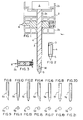
- FIG. 1 shows a retractable tip trocar assembly 1 in accordance with the invention.
- the assembly 1 includes a housing 2 including an upper housing 2a and a lower housing 2b.
- the upper housing 2a supports a shaft 3 having a distal end 3a and a proximate end 3b, and the lower housing 2b supports a trocar tube 4 such that the shaft 3 fits within the trocar tube 4.
- the upper housing 2a is separable from the lower housing 2b so that the shaft 3 can be withdrawn from the trocar tube 4.
- a mechanism A is provided for retracting the shaft 3 during use of the assembly 1.
- a piercing tip 5 is provided at the distal end 3a of the shaft 3.
- Valve means such as a trumpet valve 6 or flap valve (not shown) is provided in the lower housing 2b for automatically sealing the trocar tube 4 when the shaft 3 is removed therefrom.
- FIG. 3 shows a partial cross-section of the trumpet valve 6.
- the piercing tip 5 can be integral with the shaft 3 or can comprise a separate part, as shown in FIG. 1.
- FIGS. 8-21 Various shapes of the piercing tip 5 are shown in FIGS. 8-21.
- FIG. 8 shows a side view of a hypo-tip 5a
- FIG. 9 shows an axial end view thereof.
- FIG. 10 shows a nail-type piercing tip 5b
- FIG. 11 shows an axial end view thereof.
- FIG. 12 shows a rounded chisel-tip 5c
- FIG. 13 shows an axial end view thereof.
- FIG. 14 shows an offset two-facet tip 5d
- FIG. 15 shows an axial end view thereof.
- FIG. 16 shows a pyramidal three-facet tip 5e
- FIG. 17 shows an axial end view thereof.
- FIG. 18 shows a conical tip 5f
- FIG. 19 shows an axial end view thereof.
- FIG. 20 shows a bullet point tip 5g
- FIG. 21 shows an
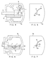
- FIG. 4 shows a cross-section of one embodiment of the upper housing 2a wherein the retracting mechanism A includes retracting means, a member and biasing means.
- the retracting means moves the piercing tip from the cutting position to the shielded position.
- the member is movable from a first position (at which the member prevents movement of the trocar obturator) to a second position (at which the member does not prevent movement of the trocar obturator), the member being held in the first position when the piercing tip is pressed against an object with an axial force above a threshold value.
- the biasing means biases the member in the second position, the biasing means applying a bias force on the member such that when the insertion force is below the threshold value the member moves from the first position to the second position and the retracting means moves the piercing tip to the shielded position.
- the member can comprise link means 7, and the retraction means and biasing means can comprise spring means 8.
- the shaft 3 is movably supported by means of the link means 7, the spring means 8 and a slider 9.
- the slider 9 slides in a track 10, and the link means 7 is bendable from a first bent configuration, as shown in FIG. 4, to a second straight configuration, as shown in FIG. 6.
- the link means 7 includes a latch arm 11 extending through a slot 12 in the upper housing 2a.
- the slot 12 is curved and includes an enlarged portion 12a and a catch 12b.
- the latch arm 11 is moved along the slot until it engages the catch 12b, as shown in dotted lines in FIG. 7.
- the link means 7 is compressed in the axial direction and the latch arm 11 disengages from the catch 12b and moves to a position at which it is free to move along the slot 12.
- the piercing tip 5 punctures a wall of a cavity
- the insertion force is released, and the force of the spring 8 deforms the link means 7 into the bent configuration shown in FIG. 4.
- the link means 7 includes a first link 13 and a second link 14.
- Links 13 and 14 can comprise a single piece of material, such as a plastic material, or they can comprise two or more discrete links which are connected together in a manner which will support the insertion force load but allow the shaft 3 to move axially when the insertion force load falls below a threshold value, such as upon breakthrough of a cavity wall.
- the upper housing 2a includes a stop 15 which engages one end of the link means 7 when an insertion force is applied to the piercing tip 5.
- the first link 13 includes a first end 13a and a second end 13b.
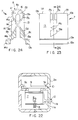
- the link 13 is U-shaped, as shown in FIG. 23.
- the link 13 includes surfaces 13c for engaging a coil of the spring means 8.
- the link 13 also includes an inclined surface 13d for engaging one arm of the spring means 8.
- the link 13 includes a flexible portion 13e.
- the link 13 also includes a surface 13f for abutting a similar surface 14f on the link 14.
- the link 14 is similar to the link 13 and includes portions 14a-f as described above with reference to link 13. As shown in FIG. 24, the spring means 8 is supported such that the coil thereof fits around surfaces 13c, 14c and the arms of the spring press against surfaces 13d and 14d.
- the end 14a of link 14 fits into a corresponding recess in slider 9, and the end 13a of link 13 fits into a corresponding recess in the upper housing 2a.
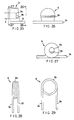
- the slider 9 is shown in FIGS. 25-27.
- the slider 9 includes a bore 9a in which the proximal end of the shaft 3 is fixedly secured.
- the slider 9 also includes recess 9b for receiving end 14a of link 14.
- the slider 9 also includes a foot 9c which rides in track 10, as shown in FIG. 22.
- FIG. 26 is a front view of the slider 9 from the direction facing recess 9b
- FIG. 27 is a rear view of the slider 9 from the direction of the bore 9a.
- the spring means 8 can comprise a torsion spring formed from a coil of wire 8a and a pair of rectilinearly extending arms 8b, 8c, extending from each end of the coil 8a.
- the arms 8b and 8c are parallel to each other, and each is tangent to the coil 8a on opposite sides of the coil 8a.
- the arms 8b, 8c are crossed such that they press against surfaces 13d, 14d of links 13, 14. In this manner, the links 13, 14 are biased toward each other so as to maintain the piercing tip 5 in the shielded position.
- the arms 8b, 8c are bent to the position shown in FIG. 6.
- the shaft 3 is retracted slightly in the axial direction so as to press the link means 7 against the stop 15.
- the force of the spring 8 deforms the link means 7 such that it assumes the position shown in FIG. 4.
- the link means 7 is capable of extending slightly when the piercing tip is in the armed position and shrinking slightly when the piercing tip is in the cutting position due to the provision of flexible portions 13e, 14e.
- the links 13, 14 will extend slightly when the abutting surfaces 13f, 14f initially separate, after which the links 13, 14 move toward each other to retract the shaft 3.
- spring 8 is effective for bending links 13, 14 from a straight configuration (as shown in FIG. 6) to a bent configuration (as shown in FIG. 4).
- the mechanism could include a torsion spring which is arranged such that the spring is unwound in the axial direction when the piercing tip is placed in the cutting or armed position.
- the device would operate as described earlier, that is, upon application of an insertion force, the spring would be held in its extended position, but when the insertion force is released, the spring would retract in the axial direction while rotating and moving the piercing tip to the shielded position.
Landscapes
- Health & Medical Sciences (AREA)
- Surgery (AREA)
- Life Sciences & Earth Sciences (AREA)
- Biomedical Technology (AREA)
- Nuclear Medicine, Radiotherapy & Molecular Imaging (AREA)
- Engineering & Computer Science (AREA)
- Pathology (AREA)
- Heart & Thoracic Surgery (AREA)
- Medical Informatics (AREA)
- Molecular Biology (AREA)
- Animal Behavior & Ethology (AREA)
- General Health & Medical Sciences (AREA)
- Public Health (AREA)
- Veterinary Medicine (AREA)
- Surgical Instruments (AREA)
Abstract
Claims (16)
- Ensemble trocart à pointe rétractable comportant :un obturateur de trocart oblong (3) s'étendant dans une direction axiale et comportant une pointe perçante (5) à son extrémité distale;un tube de trocart oblong (4) où l'obturateur de trocart est logé, la pointe perçante étant déplacable dans la direction axiale d'une position de coupe où la pointe perçante se trouve à l'extérieur d'une extrémité distale du tube de trocart à une position protégée où la pointe perçante se trouve entièrement dans le tube de trocart;un boítier de poignée de trocart (2a),une première bielle (13) dont une extrémité est reliée de manière pivotante à l'extrémité proximale de l'obturateur de trocart et dont l'autre extrémité est reliée de manière pivotante à une extrémité d'une deuxième bielle (14), l'autre extrémité de la deuxième bielle étant fixée de manière pivotante au boítier de poignée de trocart, les bielles se trouvant dans une première configuration où la pointe perçante est en position de coupe, et les bielles se trouvant dans une deuxième configuration lorsque la pointe perçante se trouve dans la position protégée; etun moyen de retrait (8) pour retirer la pointe perçante de la position de coupe à la position protégée.
- Ensemble de trocart à pointe rétractable selon la revendication 1, comportant en outre :un élément (11) déplaçable d'une première position où l'élément empêche un mouvement des bielles de la première configuration à la deuxième configuration vers une deuxième position où l'élément n'empêche pas le mouvement des bielles de la première configuration à la deuxième configuration, l'élément étant maintenu dans la première position lorsque la pointe perçante est appliquée par pression contre un objet avec une force axiale au-dessus d'une valeur seuil; etun moyen de sollicitation (8) sollicitant l'élément vers la deuxième position, le moyen de sollicitation appliquant une force de sollicitation sur l'élément de telle sorte que lorsque la force axiale est en dessous de la valeur seuil, l'élément se déplace de la première position à la deuxième position, et le moyen de retrait déplace les bielles de la première position à la deuxième position pour ramener la pointe perçante dans la position protégée, où le moyen de sollicitation amène l'élément à la deuxième position lors d'un relâchement d'une charge de force d'insertion placée sur la pointe perçante lorsque la pointe perçante est en position de coupe.
- Ensemble de trocart à pointe rétractable selon la revendication 2, où la charge de force d'insertion comporte une charge de compression agissant dans une direction axiale.
- Ensemble de trocart à pointe rétractable selon l'une des revendications précédentes, où le moyen de retrait comporte un ressort (8) relié à au moins l'une des bielles et sollicitant les bielles vers ladite deuxième configuration.
- Ensemble de trocart à pointe rétractable selon la revendication 4, où le ressort comporte un ressort à torsion.
- Ensemble de trocart à pointe rétractable selon la revendication 5, où le ressort à torsion comporte un fil ayant des premier (8a) et deuxième (8b) bras s'étendant d'une portion enroulée du fil, le premier bras exerçant une pression contre la première bielle et le deuxième bras contre la deuxième bielle.
- Ensemble de trocart à pointe rétractable selon l'une des revendications précédentes, comportant en outre une butée d'arrêt (12b) dans le boítier de poignée de trocart pour soutenir la charge de force d'insertion qui agit axialement sur la pointe perçante, l'obturateur de trocart et les première et deuxième bielles étant alignés sensiblement axialement et supportant la charge de force d'insertion contre la butée d'arrêt lorsque la pointe perçante se trouve en position de coupe et que la pointe perçante est poussée contre un objet.
- Ensemble de trocart à pointe rétractable selon l'une des revendications précédentes, où les première et deuxième bielles comportent des surfaces de butée (13f, 14f) qui sont poussées l'une contre l'autre lorsque la pointe perçante se trouve en position de coupe.
- Ensemble de trocart à pointe rétractable selon la revendication 8, où les première et deuxième bielles comprennent une seule pièce de matière plastique.
- Ensemble de trocart à pointe rétractable selon la revendication 9, où la pièce unique en plastique comporte deux éléments de liaison en plastique reliés par une section pliante (16) en matière plastique.
- Ensemble de trocart à pointe rétractable selon l'une des revendications précédentes, ou les extrémités des première et deuxième bielles qui ne sont pas reliées de manière pivotante l'une à l'autre sont rapprochées davantage lorsque la pointe perçante va vers la position protégée.
- Ensemble de trocart à pointe rétractable selon l'une des revendications précédentes, comportant en outre un bras de cliquet (11) sur l'une des bielles pour déplacer manuellement les bielles à la première configuration, le boítier de poignée de trocart incluant un moyen de cliquet (12b) pour retenir le bras de verrouillage dans une position armée à laquelle la pointe perçante se trouve en position de coupe.
- Ensemble de trocart à pointe rétractable selon la revendication 12, où une extrémité du bras de verrouillage est reliée à l'une des bielles et dont l'autre extrémité s'étend vers l'extérieur de la poignée de trocart, le moyen de cliquet comportant une fente courbée (12) dans la poignée de trocart, le bras de verrouillage étant déplaçable le long de la fente courbée, la fente courbée se terminant par une ouverture agrandie (12a) formée en partie par une surface de support contre laquelle le bras de verrouillage exerce une pression lorsque la pointe perçante se trouve dans une position armée.
- Ensemble de trocart à pointe rétractable selon la revendication 13, où la pointe perçante se trouve plus loin à l'extérieur de l'extrémité distale du tube de trocart dans la position armée que lorsque la pointe perçante se trouve en position de coupe.
- Ensemble de trocart à pointe rétractable selon la revendication 14, où le bras de verrouillage se déplace automatiquement au loin de la surface de support (12b) vers une position en alignement avec la fente courbée lorsque la pointe perçante est poussée contre un objet.
- Ensemble de trocart à pointe rétractable selon l'une des revendications précédentes, où le boítier de la poignée de trocart comporte un chemin (12) et l'arbre comporte un coulisseau (11), le coulisseau coopérant avec le chemin pour guider l'ensemble d'arbre le long du tube de trocart.
Applications Claiming Priority (3)
| Application Number | Priority Date | Filing Date | Title |
|---|---|---|---|
| US07/850,089 US5441513A (en) | 1992-03-12 | 1992-03-12 | Retracting tip trocar assembly |
| US850089 | 1992-03-12 | ||
| PCT/US1993/001744 WO1993017626A1 (fr) | 1992-03-12 | 1993-03-01 | Ensemble trocart a pointe retractable |
Publications (2)
| Publication Number | Publication Date |
|---|---|
| EP0630213A1 EP0630213A1 (fr) | 1994-12-28 |
| EP0630213B1 true EP0630213B1 (fr) | 1998-01-28 |
Family
ID=25307231
Family Applications (1)
| Application Number | Title | Priority Date | Filing Date |
|---|---|---|---|
| EP93907059A Expired - Lifetime EP0630213B1 (fr) | 1992-03-12 | 1993-03-01 | Ensemble trocart a pointe retractable |
Country Status (8)
| Country | Link |
|---|---|
| US (2) | US5441513A (fr) |
| EP (1) | EP0630213B1 (fr) |
| JP (1) | JP3307394B2 (fr) |
| AU (1) | AU671821B2 (fr) |
| CA (1) | CA2129332C (fr) |
| DE (1) | DE69316740T2 (fr) |
| ES (1) | ES2111739T3 (fr) |
| WO (1) | WO1993017626A1 (fr) |
Cited By (4)
| Publication number | Priority date | Publication date | Assignee | Title |
|---|---|---|---|---|
| DE102007040358A1 (de) * | 2007-08-27 | 2009-03-05 | Technische Universität München | Trokarrohr, Trokar, Obturator bzw. Rektoskop für die transluminale endoskopische Chirurgie über natürliche Körperöffnungen |
| US7842014B2 (en) | 2006-03-27 | 2010-11-30 | Aesculap Ag | Surgical sealing element, surgical seal, and surgical sealing system |
| US8137318B2 (en) | 2008-07-09 | 2012-03-20 | Aesculap Ag | Surgical protection device for a surgical sealing element and surgical sealing system |
| US8246586B2 (en) | 2008-07-09 | 2012-08-21 | Aesculap Ag | Surgical sealing element holder for holding a surgical sealing element and surgical sealing system |
Families Citing this family (58)
| Publication number | Priority date | Publication date | Assignee | Title |
|---|---|---|---|---|
| US5645557A (en) * | 1990-12-18 | 1997-07-08 | Yoon; Inbae | Safety penetrating instrument with triggered penetrating member retraction and safety member protrusion |
| US5645556A (en) * | 1990-12-18 | 1997-07-08 | Yoon; Inbae | Safety penetrating instrument with triggered penetrating member retraction and single or multiple safety member protrusion |
| US5466224A (en) * | 1990-12-18 | 1995-11-14 | Yoon; Inbae | Safety penetrating instrument having a triggered portal sleeve for establishing an endoscopic portal in an anatomical cavity wall |
| US5578053A (en) * | 1993-06-24 | 1996-11-26 | Yoon; Inbae | Safety needle instrument having a triggered safety member |
| US5431635A (en) * | 1990-12-18 | 1995-07-11 | Yoon; Inbae | Safety penetrating instrument having a triggered safety member for establishing an endoscopic portal in an anatomical cavity wall |
| US5645076A (en) * | 1991-08-14 | 1997-07-08 | Yoon; Inbae | Automatic retractable safety penetrating instrument |
| US5571134A (en) * | 1993-06-24 | 1996-11-05 | Yoon; Inbae | Safety penetrating instrument with penetrating member and safety member moving during penetration and triggered safety member protrusion |
| US5573545A (en) * | 1993-06-24 | 1996-11-12 | Yoon; Inbae | Safety penetrating instrument with safety member and cannula moving during penetration and triggered cannula and/or safety member protrusion |
| US5575804A (en) * | 1993-06-24 | 1996-11-19 | Yoon; Inbae | Safety penetrating instrument with cannula moving during penetration and triggered safety member protrusion |
| US5607439A (en) * | 1993-06-24 | 1997-03-04 | Yoon; Inbae | Safety penetrating instrument with penetrating member moving during penetration and triggered safety member protrusion |
| US5584848A (en) * | 1993-06-24 | 1996-12-17 | Yoon; Inbae | Safety penetrating instrument with penetrating member, safety member and cannula moving during penetration and triggered safety member protrusion |
| US5569289A (en) * | 1993-06-24 | 1996-10-29 | Yoon; Inbae | Safety penetrating instrument with penetrating member and cannula moving during penetration and triggered safety member protusion |
| US5603689A (en) * | 1994-08-05 | 1997-02-18 | L & T S.N.C. Di Ermanno Lucini & C. | Elevator device for an abdominal wall, in videolaparoscopic surgical operations |
| DE4432673A1 (de) * | 1994-09-14 | 1996-03-21 | Bernd Klemm | Operationsinstrument |
| US5916232A (en) * | 1997-10-10 | 1999-06-29 | Applied Medical Resources Corporation | Asymmetrical obturator |
| US20060015075A1 (en) * | 1999-06-22 | 2006-01-19 | Erblan Surgical Inc. | Guarded infusor needle and infusor locking system |
| US6319266B1 (en) * | 2000-03-16 | 2001-11-20 | United States Surgical Corporation | Trocar system and method of use |
| US20020161387A1 (en) * | 2000-06-22 | 2002-10-31 | Blanco Ernesto E. | Safety trocar with progressive cutting tip guards and gas jet tissue deflector |
| US20040230160A1 (en) * | 2000-06-22 | 2004-11-18 | Erblan Surgical Inc. | Safety trocar including sealing member |
| ES2334841T3 (es) * | 2000-08-08 | 2010-03-16 | Tyco Healthcare Group Lp | Pestillo de trocar moldeado. |
| US7004928B2 (en) | 2002-02-08 | 2006-02-28 | Rosedale Medical, Inc. | Autonomous, ambulatory analyte monitor or drug delivery device |
| US6692206B1 (en) * | 2002-08-16 | 2004-02-17 | Textron Inc. | Split weld cage nut assembly |
| US7052652B2 (en) | 2003-03-24 | 2006-05-30 | Rosedale Medical, Inc. | Analyte concentration detection devices and methods |
| CA2539552A1 (fr) * | 2003-09-24 | 2005-04-07 | Applied Medical Resources Corporation | Joint de trocart anti-inversion |
| US8007477B2 (en) * | 2004-03-22 | 2011-08-30 | Applied Medical Resources Corporation | Surgical access port and method of using same |
| US7419496B2 (en) * | 2004-08-03 | 2008-09-02 | Staudner Rupert A | Trocar with retractable cutting surface |
| US20060281187A1 (en) | 2005-06-13 | 2006-12-14 | Rosedale Medical, Inc. | Analyte detection devices and methods with hematocrit/volume correction and feedback control |
| EP2559381B1 (fr) | 2005-09-30 | 2014-12-31 | Intuity Medical, Inc. | Dispositif pour l'extraction et l'analyse d'un échantillon de fluide corporel |
| US8801631B2 (en) | 2005-09-30 | 2014-08-12 | Intuity Medical, Inc. | Devices and methods for facilitating fluid transport |
| US8579807B2 (en) | 2008-04-28 | 2013-11-12 | Ethicon Endo-Surgery, Inc. | Absorbing fluids in a surgical access device |
| US8690831B2 (en) | 2008-04-25 | 2014-04-08 | Ethicon Endo-Surgery, Inc. | Gas jet fluid removal in a trocar |
| US9113953B2 (en) * | 2006-07-06 | 2015-08-25 | Covidien Lp | Two-mode trocar assembly |
| DE102007024181B4 (de) * | 2007-03-05 | 2011-06-16 | Gerresheimer Regensburg Gmbh | Stechvorrichtung für die Blutentnahme mit einer Schenkelfeder |
| DE102007024173B4 (de) * | 2007-03-05 | 2010-09-09 | Gerresheimer Wilden Gmbh | Stechvorrichtung für die Blutentnahme bei medizinischen Untersuchungen |
| DE102007024183B4 (de) * | 2007-03-05 | 2011-03-03 | Gerresheimer Regensburg Gmbh | Stechvorrichtung mit Verdrehfeder |
| EP2142115B1 (fr) | 2007-04-18 | 2016-08-24 | Covidien LP | Ensemble de trocart avec dissecteur obturateur |
| US8100929B2 (en) * | 2007-06-29 | 2012-01-24 | Ethicon Endo-Surgery, Inc. | Duckbill seal with fluid drainage feature |
| AU2008229774B2 (en) | 2007-10-05 | 2013-05-16 | Covidien Lp | Two-mode bladeless trocar assembly |
| US7976501B2 (en) * | 2007-12-07 | 2011-07-12 | Ethicon Endo-Surgery, Inc. | Trocar seal with reduced contact area |
| USD700326S1 (en) | 2008-04-28 | 2014-02-25 | Ethicon Endo-Surgery, Inc. | Trocar housing |
| US9358041B2 (en) | 2008-04-28 | 2016-06-07 | Ethicon Endo-Surgery, Llc | Wicking fluid management in a surgical access device |
| US8568362B2 (en) | 2008-04-28 | 2013-10-29 | Ethicon Endo-Surgery, Inc. | Surgical access device with sorbents |
| US8273060B2 (en) | 2008-04-28 | 2012-09-25 | Ethicon Endo-Surgery, Inc. | Fluid removal in a surgical access device |
| US8870747B2 (en) | 2008-04-28 | 2014-10-28 | Ethicon Endo-Surgery, Inc. | Scraping fluid removal in a surgical access device |
| US8636686B2 (en) | 2008-04-28 | 2014-01-28 | Ethicon Endo-Surgery, Inc. | Surgical access device |
| US11235111B2 (en) | 2008-04-28 | 2022-02-01 | Ethicon Llc | Surgical access device |
| US7981092B2 (en) | 2008-05-08 | 2011-07-19 | Ethicon Endo-Surgery, Inc. | Vibratory trocar |
| EP2293719B1 (fr) | 2008-05-30 | 2015-09-09 | Intuity Medical, Inc. | Dispositif de prélèvement de liquide organique et interface de site de prélèvement |
| JP2011522594A (ja) | 2008-06-06 | 2011-08-04 | インテュイティ メディカル インコーポレイテッド | 医用診断装置及び方法 |
| US9636051B2 (en) | 2008-06-06 | 2017-05-02 | Intuity Medical, Inc. | Detection meter and mode of operation |
| US8911463B2 (en) * | 2008-06-10 | 2014-12-16 | Covidien Lp | Bladed/bladeless obturator for use in a surgical trocar assembly |
| US10278728B2 (en) * | 2009-01-30 | 2019-05-07 | St. Jude Medical, Llc | Transapical mini-introducer hemostasis valve and punch |
| CA2782047C (fr) | 2009-11-30 | 2019-10-29 | Intuity Medical, Inc. | Dispositif et procede de fourniture de materiau d'etalonnage |
| WO2011162823A1 (fr) | 2010-06-25 | 2011-12-29 | Intuity Medical, Inc. | Systèmes et procédés de surveillance de substance à analyser |
| US9782114B2 (en) | 2011-08-03 | 2017-10-10 | Intuity Medical, Inc. | Devices and methods for body fluid sampling and analysis |
| US9308020B2 (en) | 2013-03-14 | 2016-04-12 | Cook Medical Technologies Llc | Tri-fluted vascular access needle |
| US10729386B2 (en) | 2013-06-21 | 2020-08-04 | Intuity Medical, Inc. | Analyte monitoring system with audible feedback |
| CN115624669B (zh) * | 2022-12-12 | 2023-03-31 | 北京深纳普思人工智能技术有限公司 | 注针装置和具有其的给药系统 |
Family Cites Families (81)
| Publication number | Priority date | Publication date | Assignee | Title |
|---|---|---|---|---|
| US1213001A (en) * | 1916-05-02 | 1917-01-16 | Ralph S Philips | Therapeutic apparatus. |
| US2496111A (en) * | 1947-09-26 | 1950-01-31 | Turkel Henry | Biopsy needle |
| US2623521A (en) * | 1951-03-12 | 1952-12-30 | Rose Shaw | Indicating stylet needle |
| US3030959A (en) * | 1959-09-04 | 1962-04-24 | Praemeta | Surgical lancet for blood sampling |
| US3605744A (en) * | 1969-04-22 | 1971-09-20 | Edward M Dwyer | Injection apparatus and method of injecting |
| US3643649A (en) * | 1969-11-20 | 1972-02-22 | United States Surgical Corp | Mechanized tracheotome |
| US3657812A (en) * | 1970-09-28 | 1972-04-25 | G & L Ind Inc | Retractible tool holder |
| US3817251A (en) * | 1972-10-04 | 1974-06-18 | H Hasson | Laparoscope cannula |
| US3882849A (en) * | 1974-03-25 | 1975-05-13 | Khosrow Jamshidi | Soft Tissue Biopsy Device |
| US3904033A (en) * | 1974-11-08 | 1975-09-09 | Xomox Corp | Pick-guard |
| US4018228A (en) * | 1975-02-24 | 1977-04-19 | Goosen Carl C | Surgical punch apparatus |
| FR2326734A1 (fr) * | 1975-10-04 | 1977-04-29 | Wolf Gmbh Richard | Appareil d'insufflation de gaz applicable notamment au remplissage d'une cavite du corps |
| US4168699A (en) * | 1977-08-08 | 1979-09-25 | Mentor Corporation | Sampling catheter |
| US4177814A (en) * | 1978-01-18 | 1979-12-11 | KLI, Incorporated | Self-sealing cannula |
| US4220155A (en) * | 1978-05-11 | 1980-09-02 | Colorado State University Research Foundation | Apparatus for spaying large animals |
| US4210246A (en) * | 1978-11-08 | 1980-07-01 | American Can Company | Reclosable hinged blister card package |
| US4356826A (en) * | 1979-05-09 | 1982-11-02 | Olympus Optical Co., Ltd. | Stabbing apparatus for diagnosis of living body |
| US4299230A (en) * | 1979-05-09 | 1981-11-10 | Olympus Optical Co., Ltd. | Stabbing apparatus for diagnosis of living body |
| US4256119A (en) * | 1979-09-17 | 1981-03-17 | Gauthier Industries, Inc. | Biopsy needle |
| US4254762A (en) * | 1979-10-23 | 1981-03-10 | Inbae Yoon | Safety endoscope system |
| US4375815A (en) * | 1981-03-23 | 1983-03-08 | Becton Dickinson And Company | Retractable lancet assembly |
| US4393587A (en) * | 1981-04-23 | 1983-07-19 | Kloosterman William A | Spring shielded safety knife |
| US4383634A (en) * | 1981-05-26 | 1983-05-17 | United States Surgical Corporation | Surgical stapler apparatus with pivotally mounted actuator assemblies |
| US4414974A (en) * | 1981-06-09 | 1983-11-15 | General Conveyors Limited | Microsurgical knife |
| GB2111392B (en) * | 1981-11-24 | 1985-12-18 | Wellcome New Zealand | Injection appliance |
| US4411653A (en) * | 1982-01-28 | 1983-10-25 | Razi M Dean | Cannula introducer |
| US4535773A (en) * | 1982-03-26 | 1985-08-20 | Inbae Yoon | Safety puncturing instrument and method |
| US4499898A (en) * | 1982-08-23 | 1985-02-19 | Koi Associates | Surgical knife with controllably extendable blade and gauge therefor |
| US4556059A (en) * | 1982-09-03 | 1985-12-03 | Adamson Jr Howard | Spring operated tracheotome |
| GB8316824D0 (en) * | 1983-06-21 | 1983-07-27 | Microsurgical Equipment Ltd | Device for member to penetrate workpiece |
| US4601710B1 (en) * | 1983-08-24 | 1998-05-05 | United States Surgical Corp | Trocar assembly |
| JPS60179057A (ja) * | 1984-02-28 | 1985-09-12 | 雪印乳業株式会社 | 腹腔鏡用受精卵移植三重針 |
| US4559041A (en) * | 1984-06-25 | 1985-12-17 | Razi M Dean | Cannula introducers |
| AU573369B2 (en) * | 1984-07-31 | 1988-06-02 | N.J. Phillips Pty. Limited | A rumen injector |
| DE3518547C2 (de) * | 1985-05-23 | 1994-04-14 | Angiomed Ag | Hohlnadel eines Biopsiebestecks |
| US4723545A (en) * | 1986-02-03 | 1988-02-09 | Graduate Hospital Foundation Research Corporation | Power assisted arthroscopic surgical device |
| US4654030A (en) * | 1986-02-24 | 1987-03-31 | Endotherapeutics | Trocar |
| US4664654A (en) * | 1986-03-07 | 1987-05-12 | Strauss Eric C | Automatic protracting and locking hypodermic needle guard |
| US4730613A (en) * | 1986-06-13 | 1988-03-15 | Cilco, Inc. | Surgical scalpel |
| US5030206A (en) * | 1986-10-17 | 1991-07-09 | United States Surgical Corporation | Trocar |
| US4902280A (en) * | 1986-10-17 | 1990-02-20 | United States Surgical Corporation | Trocar |
| CA1303936C (fr) * | 1986-10-17 | 1992-06-23 | Jack R. Lander | Trocart |
| ATE60239T1 (de) * | 1986-11-19 | 1991-02-15 | Sterimatic Holdings Ltd | Injektionsvorrichtungen. |
| US4733662A (en) * | 1987-01-20 | 1988-03-29 | Minnesota Mining And Manufacturing Company | Tissue gripping and cutting assembly for surgical instrument |
| US4874375A (en) * | 1987-04-13 | 1989-10-17 | Ellison Arthur E | Tissue retractor |
| US4747831A (en) * | 1987-04-29 | 1988-05-31 | Phase Medical, Inc. | Cannula insertion set with safety retracting needle |
| ES2007667A6 (es) * | 1987-07-28 | 1989-07-01 | Espejo Martinez Antonio | Aparato localizador del espacio epidural |
| US4858607A (en) * | 1987-10-16 | 1989-08-22 | Pavel Jordan & Associates | Plastic device for injection and obtaining blood samples |
| WO1989003661A1 (fr) * | 1987-10-26 | 1989-05-05 | Endotherapeutics | Trocart avec verrou ameliore |
| US4931042A (en) * | 1987-10-26 | 1990-06-05 | Endotherapeutics | Trocar assembly with improved latch |
| DE3739003A1 (de) * | 1987-11-17 | 1989-05-24 | Wolf Gmbh Richard | Insufflationsgeraet fuer endoskopische eingriffe |
| US4943280A (en) * | 1987-12-31 | 1990-07-24 | United States Surgical Corporaiton | Self-seating flapper valve for an insufflation cannula assembly |
| US4869717A (en) * | 1988-04-25 | 1989-09-26 | Adair Edwin Lloyd | Gas insufflation needle with instrument port |
| US4986814A (en) * | 1988-06-13 | 1991-01-22 | Indianapolis Center For Advanced Research | One-punch catheter |
| GB8816033D0 (en) * | 1988-07-06 | 1988-08-10 | Ethicon Inc | Improved safety trocar |
| US4955870A (en) * | 1988-08-23 | 1990-09-11 | Ridderheim Kristen A | Hypodermic syringe with retractable needle |
| US4911693A (en) * | 1988-10-17 | 1990-03-27 | Paris Frassetti R | Hypodermic syringe needle guard |
| US4940458A (en) * | 1989-02-02 | 1990-07-10 | Cohn Arnold K | Epidural needle placement system |
| US4958625A (en) * | 1989-07-18 | 1990-09-25 | Boston Scientific Corporation | Biopsy needle instrument |
| US5009643A (en) * | 1989-08-09 | 1991-04-23 | Richard Wolf Medical Instruments Corp. | Self-retaining electrically insulative trocar sleeve and trocar |
| US4994042A (en) * | 1989-10-02 | 1991-02-19 | Vadher Dinesh L | Combined catheter and needle |
| US5104383A (en) * | 1989-10-17 | 1992-04-14 | United States Surgical Corporation | Trocar adapter seal and method of use |
| US5046508A (en) * | 1989-12-19 | 1991-09-10 | Jonathan Weissler | Syringe with retractable needle |
| US5049136A (en) * | 1990-01-10 | 1991-09-17 | Johnson Gerald W | Hypodermic needle with protective sheath |
| US4973316A (en) * | 1990-01-16 | 1990-11-27 | Dysarz Edward D | One handed retractable safety syringe |
| US5127909A (en) * | 1990-04-05 | 1992-07-07 | United States Surgical Corporation | Flapper valve for an insufflation cannula assembly |
| US5059184A (en) * | 1990-05-03 | 1991-10-22 | Dyke Timothy J | Hypodermic needle apparatus |
| US5196025A (en) * | 1990-05-21 | 1993-03-23 | Ryder International Corporation | Lancet actuator with retractable mechanism |
| US5114407A (en) * | 1990-08-30 | 1992-05-19 | Ethicon, Inc. | Safety mechanism for trocar |
| US5073169A (en) * | 1990-10-02 | 1991-12-17 | Steve Raiken | Trocar support |
| DK0479130T3 (da) * | 1990-10-05 | 1995-02-20 | United States Surgical Corp | Sikkerhedstrokar |
| US5116353B1 (en) * | 1990-10-05 | 1996-09-10 | Digital Voice Systems Inc | Safety trocar |
| US5226426A (en) * | 1990-12-18 | 1993-07-13 | Inbae Yoon | Safety penetrating instrument |
| US5104382A (en) * | 1991-01-15 | 1992-04-14 | Ethicon, Inc. | Trocar |
| US5092853A (en) * | 1991-02-04 | 1992-03-03 | Couvertier Ii Douglas | Automatic retractable medical needle and method |
| US5152754A (en) * | 1991-02-15 | 1992-10-06 | Minnesota Mining And Manufacturing Company | Trocar |
| US5224951A (en) * | 1991-02-19 | 1993-07-06 | Dexide, Inc. | Surgical trocar and spike assembly |
| US5192025A (en) * | 1991-07-19 | 1993-03-09 | Hu Ming Thy | Electric water jet for automobile |
| WO1993004632A1 (fr) * | 1991-08-30 | 1993-03-18 | Origin Medsystems, Inc. | Trocart a pointe retractable et mecanisme actuateur par la paume |
| US5158552A (en) * | 1991-11-04 | 1992-10-27 | American Cyanamid Company | Safety trocar instrument having a retractable trocar actuated by relief of pressure on the trocar point |
| US5246425A (en) * | 1992-09-21 | 1993-09-21 | Daniel Hunsberger | Trocar and cannula assembly |
-
1992
- 1992-03-12 US US07/850,089 patent/US5441513A/en not_active Expired - Lifetime
-
1993
- 1993-03-01 ES ES93907059T patent/ES2111739T3/es not_active Expired - Lifetime
- 1993-03-01 AU AU37797/93A patent/AU671821B2/en not_active Expired
- 1993-03-01 CA CA002129332A patent/CA2129332C/fr not_active Expired - Lifetime
- 1993-03-01 WO PCT/US1993/001744 patent/WO1993017626A1/fr not_active Ceased
- 1993-03-01 EP EP93907059A patent/EP0630213B1/fr not_active Expired - Lifetime
- 1993-03-01 DE DE69316740T patent/DE69316740T2/de not_active Expired - Lifetime
- 1993-03-01 JP JP51577593A patent/JP3307394B2/ja not_active Expired - Lifetime
-
1995
- 1995-04-12 US US08/421,354 patent/US5626598A/en not_active Expired - Lifetime
Cited By (5)
| Publication number | Priority date | Publication date | Assignee | Title |
|---|---|---|---|---|
| US7842014B2 (en) | 2006-03-27 | 2010-11-30 | Aesculap Ag | Surgical sealing element, surgical seal, and surgical sealing system |
| DE102007040358A1 (de) * | 2007-08-27 | 2009-03-05 | Technische Universität München | Trokarrohr, Trokar, Obturator bzw. Rektoskop für die transluminale endoskopische Chirurgie über natürliche Körperöffnungen |
| US8137318B2 (en) | 2008-07-09 | 2012-03-20 | Aesculap Ag | Surgical protection device for a surgical sealing element and surgical sealing system |
| US8246586B2 (en) | 2008-07-09 | 2012-08-21 | Aesculap Ag | Surgical sealing element holder for holding a surgical sealing element and surgical sealing system |
| US8696636B2 (en) | 2008-07-09 | 2014-04-15 | Aesculap Ag | Surgical sealing element holder for holding a surgical sealing element and surgical sealing system |
Also Published As
| Publication number | Publication date |
|---|---|
| US5441513A (en) | 1995-08-15 |
| DE69316740D1 (de) | 1998-03-05 |
| US5626598A (en) | 1997-05-06 |
| JP2000514315A (ja) | 2000-10-31 |
| CA2129332C (fr) | 2003-08-26 |
| DE69316740T2 (de) | 1998-06-10 |
| JP3307394B2 (ja) | 2002-07-24 |
| AU3779793A (en) | 1993-10-05 |
| WO1993017626A1 (fr) | 1993-09-16 |
| ES2111739T3 (es) | 1998-03-16 |
| AU671821B2 (en) | 1996-09-12 |
| EP0630213A1 (fr) | 1994-12-28 |
| CA2129332A1 (fr) | 1993-09-16 |
Similar Documents
| Publication | Publication Date | Title |
|---|---|---|
| US5441513A (en) | Retracting tip trocar assembly | |
| US5261891A (en) | Trocar | |
| US5104382A (en) | Trocar | |
| US5637097A (en) | Penetrating instrument having an expandable anchoring portion | |
| US5807402A (en) | Safety penetrating instrument with protective sheath, triggered penetrating member retraction and single and safety member protrusion | |
| US5411515A (en) | Obturator with rotating, self-locking and resettable safety shield | |
| US5665102A (en) | Automatic retractable safety penetrating instrument | |
| US5810866A (en) | Automatic retractable safety penetrating instrument for portal sleeve introduction | |
| US5445617A (en) | Automatic retractable safety penetrating instrument for portal sleeve introduction and method of use | |
| EP0495633A1 (fr) | Lame pour un trocart chirurgical | |
| CA2144428C (fr) | Instrument penetrant de securite a retraction automatique | |
| US5827315A (en) | Safety penetrating instrument with penetrating member protected after penetration to predetermined depth | |
| EP0511676A2 (fr) | Trocart de sécurité | |
| US5575804A (en) | Safety penetrating instrument with cannula moving during penetration and triggered safety member protrusion | |
| US5573545A (en) | Safety penetrating instrument with safety member and cannula moving during penetration and triggered cannula and/or safety member protrusion | |
| WO1996010431A1 (fr) | Instrument penetrant de securite comportant un element penetrant et une canule mobile pendant la penetration et un element de securite saillant commande | |
| JPH11504234A (ja) | 側方拡張自在バネ片を備えた収縮自在安全挿通具 | |
| US5645557A (en) | Safety penetrating instrument with triggered penetrating member retraction and safety member protrusion | |
| US5591189A (en) | Safety penetrating instrument with safety member moving during penetration and triggered safety member protrusion | |
| US5571134A (en) | Safety penetrating instrument with penetrating member and safety member moving during penetration and triggered safety member protrusion | |
| US5573511A (en) | Retractable safety penetrating instrument with safety probe | |
| US5584849A (en) | Retractable safety penetrating instrument with safety shield and multiple triggering and/or moving components | |
| US5466224A (en) | Safety penetrating instrument having a triggered portal sleeve for establishing an endoscopic portal in an anatomical cavity wall | |
| US5603719A (en) | Retractable safety trocar with multiple triggering and/or moving components |
Legal Events
| Date | Code | Title | Description |
|---|---|---|---|
| PUAI | Public reference made under article 153(3) epc to a published international application that has entered the european phase |
Free format text: ORIGINAL CODE: 0009012 |
|
| 17P | Request for examination filed |
Effective date: 19940902 |
|
| AK | Designated contracting states |
Kind code of ref document: A1 Designated state(s): DE ES FR GB IT |
|
| 17Q | First examination report despatched |
Effective date: 19960315 |
|
| GRAG | Despatch of communication of intention to grant |
Free format text: ORIGINAL CODE: EPIDOS AGRA |
|
| GRAG | Despatch of communication of intention to grant |
Free format text: ORIGINAL CODE: EPIDOS AGRA |
|
| GRAH | Despatch of communication of intention to grant a patent |
Free format text: ORIGINAL CODE: EPIDOS IGRA |
|
| RAP1 | Party data changed (applicant data changed or rights of an application transferred) |
Owner name: UNITED STATES SURGICAL CORPORATION |
|
| GRAH | Despatch of communication of intention to grant a patent |
Free format text: ORIGINAL CODE: EPIDOS IGRA |
|
| GRAA | (expected) grant |
Free format text: ORIGINAL CODE: 0009210 |
|
| AK | Designated contracting states |
Kind code of ref document: B1 Designated state(s): DE ES FR GB IT |
|
| REF | Corresponds to: |
Ref document number: 69316740 Country of ref document: DE Date of ref document: 19980305 |
|
| REG | Reference to a national code |
Ref country code: ES Ref legal event code: FG2A Ref document number: 2111739 Country of ref document: ES Kind code of ref document: T3 |
|
| ET | Fr: translation filed | ||
| ITF | It: translation for a ep patent filed | ||
| PLBE | No opposition filed within time limit |
Free format text: ORIGINAL CODE: 0009261 |
|
| STAA | Information on the status of an ep patent application or granted ep patent |
Free format text: STATUS: NO OPPOSITION FILED WITHIN TIME LIMIT |
|
| 26N | No opposition filed | ||
| REG | Reference to a national code |
Ref country code: GB Ref legal event code: IF02 |
|
| PGFP | Annual fee paid to national office [announced via postgrant information from national office to epo] |
Ref country code: FR Payment date: 20120406 Year of fee payment: 20 |
|
| PGFP | Annual fee paid to national office [announced via postgrant information from national office to epo] |
Ref country code: GB Payment date: 20120326 Year of fee payment: 20 Ref country code: IT Payment date: 20120327 Year of fee payment: 20 |
|
| PGFP | Annual fee paid to national office [announced via postgrant information from national office to epo] |
Ref country code: DE Payment date: 20120328 Year of fee payment: 20 |
|
| REG | Reference to a national code |
Ref country code: DE Ref legal event code: R071 Ref document number: 69316740 Country of ref document: DE |
|
| REG | Reference to a national code |
Ref country code: GB Ref legal event code: PE20 Expiry date: 20130228 |
|
| PG25 | Lapsed in a contracting state [announced via postgrant information from national office to epo] |
Ref country code: DE Free format text: LAPSE BECAUSE OF EXPIRATION OF PROTECTION Effective date: 20130302 Ref country code: GB Free format text: LAPSE BECAUSE OF EXPIRATION OF PROTECTION Effective date: 20130228 |
|
| PGFP | Annual fee paid to national office [announced via postgrant information from national office to epo] |
Ref country code: ES Payment date: 20120326 Year of fee payment: 20 |
|
| REG | Reference to a national code |
Ref country code: ES Ref legal event code: FD2A Effective date: 20130718 |
|
| PG25 | Lapsed in a contracting state [announced via postgrant information from national office to epo] |
Ref country code: ES Free format text: LAPSE BECAUSE OF EXPIRATION OF PROTECTION Effective date: 20130302 |