EP0630458B1 - Method and apparatus for repairing conduits - Google Patents
Method and apparatus for repairing conduits Download PDFInfo
- Publication number
- EP0630458B1 EP0630458B1 EP93906413A EP93906413A EP0630458B1 EP 0630458 B1 EP0630458 B1 EP 0630458B1 EP 93906413 A EP93906413 A EP 93906413A EP 93906413 A EP93906413 A EP 93906413A EP 0630458 B1 EP0630458 B1 EP 0630458B1
- Authority
- EP
- European Patent Office
- Prior art keywords
- sleeve
- conduit
- grout
- installation position
- grouting
- Prior art date
- Legal status (The legal status is an assumption and is not a legal conclusion. Google has not performed a legal analysis and makes no representation as to the accuracy of the status listed.)
- Expired - Lifetime
Links
- 238000000034 method Methods 0.000 title claims abstract description 65
- 239000011440 grout Substances 0.000 claims abstract description 116
- 239000000463 material Substances 0.000 claims abstract description 84
- 230000008439 repair process Effects 0.000 claims abstract description 79
- 238000009434 installation Methods 0.000 claims description 137
- 239000012815 thermoplastic material Substances 0.000 claims description 24
- XLYOFNOQVPJJNP-UHFFFAOYSA-N water Substances O XLYOFNOQVPJJNP-UHFFFAOYSA-N 0.000 claims description 23
- 238000010438 heat treatment Methods 0.000 claims description 15
- 229920003023 plastic Polymers 0.000 claims description 11
- 239000004033 plastic Substances 0.000 claims description 11
- 239000002904 solvent Substances 0.000 claims description 10
- 239000011248 coating agent Substances 0.000 claims description 8
- 238000000576 coating method Methods 0.000 claims description 8
- -1 polyethylene Polymers 0.000 claims description 8
- 238000005728 strengthening Methods 0.000 claims description 8
- 239000004698 Polyethylene Substances 0.000 claims description 7
- 230000000712 assembly Effects 0.000 claims description 7
- 238000000429 assembly Methods 0.000 claims description 7
- 229920000573 polyethylene Polymers 0.000 claims description 7
- 229920002678 cellulose Polymers 0.000 claims description 5
- 239000001913 cellulose Substances 0.000 claims description 5
- 239000010935 stainless steel Substances 0.000 claims description 4
- 229910001220 stainless steel Inorganic materials 0.000 claims description 4
- 239000003054 catalyst Substances 0.000 claims description 3
- 230000000295 complement effect Effects 0.000 claims description 3
- 229920000298 Cellophane Polymers 0.000 claims description 2
- 239000004593 Epoxy Substances 0.000 claims description 2
- 239000000853 adhesive Substances 0.000 claims description 2
- 230000001070 adhesive effect Effects 0.000 claims description 2
- 229920002635 polyurethane Polymers 0.000 claims description 2
- 239000004814 polyurethane Substances 0.000 claims description 2
- 239000002184 metal Substances 0.000 claims 2
- 239000010410 layer Substances 0.000 description 25
- 229920001169 thermoplastic Polymers 0.000 description 10
- 239000004416 thermosoftening plastic Substances 0.000 description 10
- 239000006260 foam Substances 0.000 description 9
- 238000007789 sealing Methods 0.000 description 9
- 229920005989 resin Polymers 0.000 description 8
- 239000011347 resin Substances 0.000 description 8
- 238000002347 injection Methods 0.000 description 6
- 239000007924 injection Substances 0.000 description 6
- 238000009412 basement excavation Methods 0.000 description 5
- 230000006378 damage Effects 0.000 description 5
- 230000000694 effects Effects 0.000 description 5
- 238000004891 communication Methods 0.000 description 4
- 238000002844 melting Methods 0.000 description 4
- 230000008018 melting Effects 0.000 description 4
- 230000002093 peripheral effect Effects 0.000 description 4
- 239000004800 polyvinyl chloride Substances 0.000 description 4
- 239000002351 wastewater Substances 0.000 description 4
- YXFVVABEGXRONW-UHFFFAOYSA-N Toluene Chemical compound CC1=CC=CC=C1 YXFVVABEGXRONW-UHFFFAOYSA-N 0.000 description 3
- 230000003213 activating effect Effects 0.000 description 3
- 230000006866 deterioration Effects 0.000 description 3
- 230000004927 fusion Effects 0.000 description 3
- 239000003973 paint Substances 0.000 description 3
- 229920000915 polyvinyl chloride Polymers 0.000 description 3
- 230000008569 process Effects 0.000 description 3
- 239000007921 spray Substances 0.000 description 3
- 229910000831 Steel Inorganic materials 0.000 description 2
- 239000007767 bonding agent Substances 0.000 description 2
- 239000004927 clay Substances 0.000 description 2
- 230000006835 compression Effects 0.000 description 2
- 238000007906 compression Methods 0.000 description 2
- 230000008020 evaporation Effects 0.000 description 2
- 238000001704 evaporation Methods 0.000 description 2
- 239000000835 fiber Substances 0.000 description 2
- 238000005187 foaming Methods 0.000 description 2
- 230000000670 limiting effect Effects 0.000 description 2
- 239000007788 liquid Substances 0.000 description 2
- 239000011148 porous material Substances 0.000 description 2
- 238000005096 rolling process Methods 0.000 description 2
- 239000000243 solution Substances 0.000 description 2
- 239000010959 steel Substances 0.000 description 2
- 229910021532 Calcite Inorganic materials 0.000 description 1
- 239000004821 Contact adhesive Substances 0.000 description 1
- 230000002730 additional effect Effects 0.000 description 1
- XAGFODPZIPBFFR-UHFFFAOYSA-N aluminium Chemical compound [Al] XAGFODPZIPBFFR-UHFFFAOYSA-N 0.000 description 1
- 229910052782 aluminium Inorganic materials 0.000 description 1
- 150000004945 aromatic hydrocarbons Chemical class 0.000 description 1
- 230000015572 biosynthetic process Effects 0.000 description 1
- 238000006243 chemical reaction Methods 0.000 description 1
- 239000003795 chemical substances by application Substances 0.000 description 1
- 239000011247 coating layer Substances 0.000 description 1
- 239000002131 composite material Substances 0.000 description 1
- 238000010276 construction Methods 0.000 description 1
- 230000001419 dependent effect Effects 0.000 description 1
- 239000013013 elastic material Substances 0.000 description 1
- 230000005611 electricity Effects 0.000 description 1
- 239000003822 epoxy resin Substances 0.000 description 1
- 230000003090 exacerbative effect Effects 0.000 description 1
- 239000000945 filler Substances 0.000 description 1
- 239000012530 fluid Substances 0.000 description 1
- 238000005755 formation reaction Methods 0.000 description 1
- 230000001771 impaired effect Effects 0.000 description 1
- 230000008595 infiltration Effects 0.000 description 1
- 238000001764 infiltration Methods 0.000 description 1
- 230000002401 inhibitory effect Effects 0.000 description 1
- 238000003780 insertion Methods 0.000 description 1
- 230000037431 insertion Effects 0.000 description 1
- 238000011900 installation process Methods 0.000 description 1
- 238000009413 insulation Methods 0.000 description 1
- 230000005923 long-lasting effect Effects 0.000 description 1
- 239000000203 mixture Substances 0.000 description 1
- 239000004745 nonwoven fabric Substances 0.000 description 1
- 230000036961 partial effect Effects 0.000 description 1
- 230000000149 penetrating effect Effects 0.000 description 1
- 229920000647 polyepoxide Polymers 0.000 description 1
- 229920001296 polysiloxane Polymers 0.000 description 1
- 238000003825 pressing Methods 0.000 description 1
- 230000009467 reduction Effects 0.000 description 1
- 230000002829 reductive effect Effects 0.000 description 1
- 230000000717 retained effect Effects 0.000 description 1
- 238000011268 retreatment Methods 0.000 description 1
- 229920006395 saturated elastomer Polymers 0.000 description 1
- 238000002791 soaking Methods 0.000 description 1
- 239000002689 soil Substances 0.000 description 1
- 230000007480 spreading Effects 0.000 description 1
- 238000003892 spreading Methods 0.000 description 1
- 230000003313 weakening effect Effects 0.000 description 1
Images



Classifications
-
- F—MECHANICAL ENGINEERING; LIGHTING; HEATING; WEAPONS; BLASTING
- F16—ENGINEERING ELEMENTS AND UNITS; GENERAL MEASURES FOR PRODUCING AND MAINTAINING EFFECTIVE FUNCTIONING OF MACHINES OR INSTALLATIONS; THERMAL INSULATION IN GENERAL
- F16L—PIPES; JOINTS OR FITTINGS FOR PIPES; SUPPORTS FOR PIPES, CABLES OR PROTECTIVE TUBING; MEANS FOR THERMAL INSULATION IN GENERAL
- F16L55/00—Devices or appurtenances for use in, or in connection with, pipes or pipe systems
- F16L55/16—Devices for covering leaks in pipes or hoses, e.g. hose-menders
- F16L55/162—Devices for covering leaks in pipes or hoses, e.g. hose-menders from inside the pipe
- F16L55/163—Devices for covering leaks in pipes or hoses, e.g. hose-menders from inside the pipe a ring, a band or a sleeve being pressed against the inner surface of the pipe
-
- F—MECHANICAL ENGINEERING; LIGHTING; HEATING; WEAPONS; BLASTING
- F16—ENGINEERING ELEMENTS AND UNITS; GENERAL MEASURES FOR PRODUCING AND MAINTAINING EFFECTIVE FUNCTIONING OF MACHINES OR INSTALLATIONS; THERMAL INSULATION IN GENERAL
- F16L—PIPES; JOINTS OR FITTINGS FOR PIPES; SUPPORTS FOR PIPES, CABLES OR PROTECTIVE TUBING; MEANS FOR THERMAL INSULATION IN GENERAL
- F16L55/00—Devices or appurtenances for use in, or in connection with, pipes or pipe systems
- F16L55/18—Appliances for use in repairing pipes
Definitions
- the present invention relates to methods and apparatuses for repairing conduits. More particularly, the invention is directed to methods and apparatuses for repairing damaged, weakened, or leaking conduits that are located in areas to which it is difficult to gain access, for example, sewer pipes or other conduits that are located underground.
- Conduit systems for carrying water or wastewater, for example, and other liquid and fluid conveyance systems, as well as conduit systems that house communication lines, for example, are typically located underground and, in general, are not easily accessible after installation. Over a period of time, such conduit systems become damaged, weakened, or otherwise begin to deteriorate and leak at the joints between adjacent conduit sections, for example. Such deterioration is caused, for example, by the settling of the surrounding earth adjacent the conduit system, by deterioration of the joints themselves over time, and/or by the growth of roots from trees and other plants.
- wastewater can begin to leak from the damaged conduit and create problems of pollution, for example.
- damaged conduit sections invite the intrusion of rainwater into the system, adding to the volume of water carried to the treatment facility, thereby overburdening it.
- damage to the conduit can result in interruption of the service provided.
- deteriorated conduits for liquid conveyance systems can soak the surrounding terrain, sometimes creating sinkholes and exacerbating drainage problems.
- service lines for gas, electricity, communications and other services which themselves are not initially in need of repair, become damaged due to the re-settling of the water-saturated terrain in which they are located, thereby disabling same.
- support for buildings and bridges, for example, provided by the terrain in which a leaking conduit is located can become weakened, thereby risking additional property damage or more serious concerns including loss of life.
- the latter-mentioned implementation includes the use of a compressible covering or gasket that is secured adjacent the outer surface of a sleeve liner to thereby form a composite liner/gasket combination.
- the sleeve and gasket combination is then coiled and inserted into a damaged conduit section, whereafter a "sewer plug", that is, an expandable air bag or, alternatively, any other internal means for expansion, forces the sleeve radially outwardly until the gasket is compressed against the inner surface of the damaged conduit section.
- the internal expansion means is deactivated, whereby the sleeve is permitted to retract, that is, recoil slightly, thereby permitting the overlapping edges of the sleeve to become locked, due to a particular structural configuration of the edges.
- a device for sealing the joint of large diameter pipes, such as gas mains and water mains, is disclosed in U.S. Patent No. 4,346,922.
- the device includes a cylindrical member made of an elastic material for covering the inside periphery of the pipe joint and circular expanding members for expanding the cylindrical member against the pipe joint.
- Belt members, impregnated with a bonding agent, such as epoxy resin, are positioned on the outside peripheral surface of the cylindrical member, at its ends, whereby the bonding agent is squeezed out by pressure, thereby obtaining an airtight and watertight bond between the outside peripheral surface of the cylindrical member at both of its longitudinal ends and the inside peripheral surfaces of the pipes.
- U.S. Patent No. 4,361,451 discloses a process for internally lining a conduit by coating the inner wall of the conduit with a first resin, coating the outer wall of a sleeve with a second resin, thereafter expanding the sleeve against the inner wall of the conduit, and maintaining pressure until the resins have become polymerized.
- a system for repairing damaged pipes internally is also described in U.S. Patent No. 4,647,072.
- a repair sleeve is used, primarily for repairing damaged wastewater pipes in which access to a damaged pipe section is difficult.
- the repair sleeve is a flexible tubular member and is expanded against the damaged pipe with a spiral spring positioned within the flexible tubular member.
- U.K. Patent Application No. 2,136,912 discloses the repair of a damaged underground pipe by wrapping a sleeve around a collapsible inflatable bag, impregnating the sleeve with resin and expanding the sleeve against the damaged pipe until the resin is set.
- any sealing of cracks or joints with resin or grout are only good for the short term and, therefore, require subsequent retreatment.
- the present invention provides methods and apparatus for internally repairing conduits that are more efficiently implemented than those known in the art. That is, the present invention is simpler and less costly than known methods and apparatus. Further, the present invention provides methods and apparatus that do not require significant internal pressures to be applied to the damaged conduit section and, therefore, that do not risk the possibility of additional damage to the damaged and/or weakened conduit section. Still further, conduit joints repaired with the methods and apparatus of the present invention are stabilized, are completely sealed, and the repair is long-lasting.
- the present invention can be used for repairing offset joints, separated joints, longitudinal and radial cracks, small holes and cavities, and it serves to restore structural integrity and to provide a water-tight seal for stopping infiltration, exfiltration, and leaks.
- the present invention provides a conduit repair apparatus and method as defined in claims 1 and 27 respectively hereinafter. Compared with known methods and apparatus, the present invention results in little or no radial force being exerted on the inner surface of the conduit under repair.
- an annular grouting area is defined between the outer surface of the sleeve, or an outer surface of a covering on the sleeve, if used, and the inner surface of the conduit under repair.
- the grouting area is limited at the longitudinal end portions of the sleeve by stop members.
- the stop members can be structural formations made in the end portions of the sleeves themselves, such as flared end portions, separate members extending around the end portions, or a combination thereof.
- the ends of the sleeve could include both flared portions and additional stop members located just longitudinally inwardly of the flared end portions to assist the flared end portions in containing grout within the grouting area.
- the stop members are coiled with the remainder of the sleeve in the pre-installation position. Further, in certain embodiments of the invention, only the stop members, and not the outer surface of the sleeve itself, engage the inner surface of the conduit under repair.
- an expanding grout is activated in the grouting area between the sleeve and the inner surface conduit section under repair.
- One feature of the expandable grout is that it provides, or assists in providing, a force to effect the locking of the sleeve in its uncoiled installation position.
- additional means could be provided for the purpose of effecting the locking of the sleeve.
- one or more elastic bands could be placed around the sleeve in the coiled position so that, once the expanding force is removed, after reaching a slightly over-expanded condition, the elastic bands provide a recoil force directed toward the aforementioned locking.
- the means for locking the sleeve in the uncoiled installation position can comprise any number of forms. For example, along one edge of the coiled sleeve, a series of punched-out projecting tangs are effective, after the aforementioned slight over-expansion of the sleeve, for receiving the opposite edge of the sleeve.
- the locking of the sleeve in the uncoiled position does not require an initial over-expansion of the sleeve.
- the present invention includes the use of a thermosettable, thermoplastic or thermofusible coating on the outer surface of the sleeve so that, after expansion of the sleeve into the uncoiled installation position, the coating is heated, thereby melting same, including the melting of the coating on the overlapped edges of the sleeve. Upon removal of the heating source, the edges of the sleeve are thereby welded together.
- One method of heating and melting the layer of thermoplastic coating is by means of resistance elements embedded in the coating layer.
- the present invention provides embodiments for use with both "wet" and "dry” conduits. That is, in some repair environments, the conduit system of section in need of repair contains a significant amount of water, for example, either flowing or stagnant. In certain situations, the water or flow of water could be removed for the time needed to perform the repair and, consequently, the type of repair method chosen would not need to take into account the presence of water. On the other hand, should water be present that cannot be pumped out or otherwise removed, certain embodiments of the present invention can be best utilized to render the presence of water irrelevant or, at least, minimally significant.
- the conduit repair apparatus of the invention may include a sleeve member including (i) a sheet of material having an outer surface and being movable from a coiled pre-installation position, in which the sheet of material generally surrounds a longitudinal axis, to an uncoiled installation position; and (ii) a pair of longitudinally spaced-apart stop members affixed to the outer surface of the sheet of material, an annular area thereby being limited, in the uncoiled installation position, by (1) the outer surface of the sheet of material, (2) the pair of stop members, and (3) an inner surface of a conduit to be repaired.
- a quantity of grout is placed in the annular area.
- the material from which the sleeve is made can include stainless steel, plastic coated steel, and plastic.
- the sheet of material has a pair of longitudinally extending opposite edge regions, and the stop members have a length extending generally from one of the pair of edge regions to another of the pair of edge regions.
- each of the pair of longitudinally spaced-apart stop members includes an elastic band surrounding the sleeve member in the coiled pre-installation position to thereby exert a force on the sleeve member in a direction favoring the coiled pre-installation position.
- the pair of longitudinally spaced-apart stop members include opposite end regions of the sheet of material which are flared outwardly from an outer surface of the sheet of material for contacting the inner surface of the conduit to be repaired in the uncoiled installation position. More specifically, the flared opposite end regions are radially flexible relative to the remainder of the sleeve member, the apparatus further including at least one layer of tape over an outer surface of each of the flared opposite end regions.
- the conduit repair apparatus includes a sleeve member including (i) a sheet of material having an outer surface and being movable from a coiled pre-installation position, in which the sheet of material generally surrounds a longitudinal axis, to an uncoiled installation position; (ii) at least one elastic band surrounding the sleeve member for exerting a force on the sleeve in a direction favoring the coiled pre-installation position; and (iii) a first longitudinal edge portion and a second longitudinal edge portion, the first longitudinal edge portion and the second longitudinal edge portion overlapping at least in the coiled pre-installation position and, in the uncoiled installation position, having complementary means for locking the sleeve member in the uncoiled installation position.
- the conduit repair apparatus includes (a) a sleeve member including (i) a sheet of material having an outer surface and an inner surface and being movable from a coiled pre-installation position, to an uncoiled installation position, at least two edge regions of the sheet of material overlapping in the uncoiled installation position; and (ii) a layer of thermoplastic material on the outer surface and the inner surface of the sheet of material, and (b) means for heating the thermoplastic material to thereby fuse the overlapping edge regions of the sheet of material together in the uncoiled installation position.
- the means for heating can include an electrical resistance means embedded in the thermoplastic material or a device for conducting heat internally of the sleeve member.
- the conduit repair apparatus includes a sleeve member including a sheet of material made of a plastic material and being movable from a coiled pre-installation position, to an uncoiled installation position, at least two edge regions of the sheet of material overlapping in the uncoiled installation position, and a solvent for partially dissolving the two overlapping edge regions for fusing the overlapping edge regions, upon evaporation of the solvent, in the uncoiled installation position.
- the conduit repair apparatus includes a sleeve member including:
- a means for locking the first longitudinal edge portion and the second longitudinal edge portion of the sheet to form the sheet into a generally tubular configuration is provided.
- a covering could be placed upon the outer surface of the sleeve if, for example, it were desired to reduce the size of the grouting area and to thereby reduce the quantity of grout needed for a given installation.
- a porous gasket is placed around the grouting sleeve for being infused with a quantity of grout.
- the porous gasket is preferably made of an open-celled material. It is also contemplated to provide a strengthening covering on a side of the gasket to be placed adjacent the grouting sleeve to provide peripheral strength to the gasket and to permit it to slide relative to the grouting sleeve as the grouting sleeve expands from the coiled position to the uncoiled position.
- the open-celled material can comprise cellulose and the strengthening layer can comprise a polyethylene sheet.
- the porous gasket is impregnated with a quantity of grout, the porous gasket placed around the grouting sleeve. At least one elastic band is then placed around the the porous gasket for retaining the porous gasket upon the grouting sleeve.
- the grout can be a member selected from the group consisting of a water-reactive expanding polyurethane grout; a water-reactive gel-forming grout; an epoxy hardening grout; and a cementitious grout.
- thermoplastic material can be placed upon the outer surface of the grouting sleeve.
- means for heating the thermoplastic material and fusing overlapping regions of the sleeve is provided.
- the heating means can take the form of resistance elements embedded into the thermoplastic material.
- the heating means can take the form of a jacket for surrounding the expandable air plug, that is, the internal expansion means, for conductively heating the thermoplastic coating from within.
- the conduit repair apparatus of the invention includes a sleeve made of a plastic material and a quantity of solvent is provided for fusing overlapping portions of the sleeve in the uncoiled installation position.
- the sleeve has a layer of thermoplastic material on the outer surface and the inner surface thereof, the sleeve member being movable from a coiled pre-installation position, to an uncoiled installation position, at least two edge regions of the sheet of material overlapping in the uncoiled installation position, the method including the steps of:
- the sleeve member includes a sheet of material made of a plastic material and is movable from a coiled pre-installation position, to an uncoiled installation position, at least two edge regions of the sheet of material overlapping in the uncoiled installation position, the method including the steps of:
- the grouting sleeve has an outer surface, a pair of longitudinally extending edges and a pair of opposite end portions, the edges extending from one of the pair of end portions to the other of the end portions, and the pair of longitudinally extending edges overlapped in a coiled pre-installation position and at least one of the edges having a device for locking the one of the edges to a portion of the other of the edges, the method including the steps of:
- the grouting sleeve has an outer surface, and a pair of longitudinally extending edges and a pair of opposite end portions, the edges extending from one of the pair of end portions to the other of the end portions, and the pair of longitudinally extending edges being overlapped in a coiled pre-installation position, at least one of the edges having a device for locking the one of the edges to a portion of the other of the edges, and at least one elastic band surrounding the grouting sleeve, the method including the steps of:
- the grouting sleeve has an outer surface, a pair of longitudinally extending edges and a pair of opposite end portions, the edges extending from one of the pair of end portions to the other of the end portions, each of the pair of opposite end portions having an outwardly projecting flexible flare, and the pair of longitudinally extending edges being overlapped in a coiled pre-installation position, the method including the steps of:
- the step of placing the grout around the grouting sleeve when the grouting sleeve is in the coiled pre-installation position is included. More specifically, according to this preferred aspect of the invention, the step of placing grout around the grouting sleeve comprises the steps of placing a porous gasket around the grouting sleeve; and infusing grout into the porous gasket. In a still further preferred aspect of the invention, the step of infusing grout into the porous gasket comprises the step of placing the grouting sleeve having the porous gasket around it into a container of grout.
- the gasket is secured to the grouting sleeve by means of an adhesive.
- the gasket is secured to the grouting sleeve by means of a mechanical attachment device including a member selected from the group consisting of at least one elastic band encircling the gasket and grouting sleeve; at least one spring-like wire encircling the gasket and grouting sleeve; and at least one hook fixed to the grouting sleeve and to the gasket.
- the step of infusing grout into the porous gasket comprises the steps of affixing a roller assembly to each end of the grouting sleeve in the coiled pre-installation position of the grouting sleeve, each of the roller assemblies having a handle; placing the grouting sleeve having the porous gasket around it into a container of grout; and rotating the grouting sleeve and gasket about a longitudinal axis of the sleeve.
- the method may include the step of applying water or a catalyst to the grout.
- the method may include the step of applying water to the grout during the step of forcing the grouting sleeve to expand from the coiled pre-installation position to an uncoiled installation position.
- the method further includes the step of heating the thermoplastic material.
- the step of positioning the grouting sleeve within a conduit to be repaired includes the steps of placing the grouting sleeve upon a vehicle and transporting the grouting sleeve to the conduit to be repaired by means of the vehicle.
- the step of positioning the grouting sleeve within a conduit may comprise the step of placing the grouting sleeve within a plurality of conduit sections, bridging a joint between two adjacent conduit sections.
- each of the pair of longitudinally extending edges has a locking configuration for engagement with a complementary locking configuration on the other of the pair of longitudinally extending edges
- the step of expanding the sleeve further including the step of expanding the sleeve until the locking configurations on the longitudinally extending edges become engaged, thereby locking the sleeve against recoil.
- the step of expanding the sleeve further comprises the step of expanding the sleeve until the outwardly projecting flares contact the inner surface of the conduit, the sleeve exerting pressure on the inner surface of the conduit only through the outwardly projecting flares; and permitting the sleeve to recoil to the uncoiled installation position.
- the method before the step of positioning the grouting sleeve within a conduit, includes the step of placing at least one elastic band around the grouting sleeve; and the step of expanding the sleeve further comprising the steps of expanding the sleeve until the outwardly projecting flares contact the inner surface of the conduit, the sleeve exerting pressure on the inner surface of the conduit only through the outwardly projecting flares, and permitting the sleeve to recoil to the uncoiled installation position with the assistance of the at least one elastic band.
- the method includes the step of placing a quantity of stop material adjacent an inside surface of each of the outwardly projecting flares.
- the method includes the step of injecting grout into the annular space.
- the method before the step of positioning the grouting sleeve within a conduit, includes the step of attaching a syringe to the grouting sleeve when the grouting sleeve is in the coiled pre-installation position, wherein the step of injecting grout into the annular space comprises injecting grout through the syringe and into the annular space.
- the method may include the step of placing at least one elastic band around the grouting sleeve.
- a significant aspect of the present invention is the structural configuration and function of the inner conduit liner, or sleeve member. As will be further discussed below, due to this structural configuration of the sleeve, less pressure is exerted on the inner surface of the damaged or weakened conduit section under repair during the installation of the sleeve.
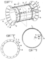
- Fig. 1 the grouting sleeve 1 of the invention is shown in its uncoiled expanded and locked position. For the sake of simplicity of illustration, only the sleeve is shown in Fig. 1, no grout being located on the outer surface 2 of the sleeve 1.
- an outwardly projecting flare 3 including an outer flare surface 4 which generally provides an extension of the outer surface 2 of the sleeve.
- the angle of the flares or flare portions 3 relative to the outer surface 2 of the sleeve is shown to be approximately 45°, other angles can be utilized and still enable the sleeve to meet the objectives further described below.
- the dimensions of the sleeve can be any of a variety of dimensions, dependent upon the internal diameter and the length of the damaged or weakened area of the conduit section to be repaired.
- the invention can be used to repair and/or seal polyvinyl chloride (PVC) and clay pipe, for example, including 15.2cm (six inch) PVC pipe and standard 25.4cm (10 inch) clay pipe, having an internal diameter of 24.8cm (9.75 inches).
- PVC polyvinyl chloride
- clay pipe for example, including 15.2cm (six inch) PVC pipe and standard 25.4cm (10 inch) clay pipe, having an internal diameter of 24.8cm (9.75 inches).
- the invention is suitable for internally repairing conduits, pipes, and sections thereof having a wide range of diameters.
- a sleeve could have a length of 30.5cm (12 inches), 61.0cm (24 inches), or 91.4cm (36 inches), for example, and an outer diameter of 15.2, 20.3, 25.4, 30.5, 38.1, 53.3 or 61.0cm (6, 8, 10, 12, 15, 21 or 24 inches), when expanded to the uncoiled installation position.
- the material from which the sleeve is formed can have a thickness of from 26 through 18 gauge, preferably 22 or 24, and can be formed from stainless steel, in which type 304 could be considered standard, although type 316 could also be used.
- the sleeve 1 can be made from non-stainless steel, aluminum, plastic, such as PVC, for example. In short, a range of materials and dimensions could be used in constructing the sleeve, the selection being limited only to the extent that the function of the sleeve, as described herein, would be significantly impaired.
- Fig. 2 shows the grouting sleeve of Fig. 1 viewed from an end thereof in the direction of arrow II.
- the flared portions 3 of the sleeve 1 are constructed by having made a series of spaced cuts 7 along the end of the material from which the sleeve is made, around the periphery of the sleeve 1 when the sheet of material is formed into a coiled tubular configuration as shown in Fig. 1, thereby producing a series of flare elements 8.
- the cuts 7 are transformed into the V shape shown in the end view of Fig. 2.
- a locking arrangement is provided by means of which the longitudinal edge regions 9, 10 of the sleeve are locked together as further described below. Any adequate locking arrangement can be utilized, although the present invention contemplates the use of a locking arrangement which is "self-actuable", i.e., one that is engaged without direct manipulation thereof.
- tangs or projecting members 5a can be punched from the sleeve itself, thereby projecting away from the surface of the sleeve.
- generally triangular openings 5b can be seen in the upper surface of the sleeve 1, the openings from which the projecting members 5a are formed.
- a portion of the longitudinal edge region 10 can be seen through the openings 5b.
- the projecting members are shown projecting inwardly, whereby the longitudinal edge of edge region 10 is captured by the projecting members extending from edge region 9.
- other locking configurations can be utilized, if desired.
- the grouting sleeve 1 has been described as being movable from a coiled pre-installation position to an uncoiled installation position.
- the latter position refers to the configuration of the sleeve as shown in Figs. 1 and 3, for example. It is clearly shown that even in the "uncoiled" position, the longitudinal edge regions 9, 10 of the sleeve are overlapped to a slight degree (or to a significant degree in later described embodiments) and, therefore, could be described as being “coiled” to various degrees. Nevertheless, the sleeve in the installation position is referred herein as being "uncoiled" relative to the pre-installation position.
- edge portions or regions 9 and 10 extend depend upon the type of sleeve under consideration and could extend substantially around the sleeve member if significant portions of the sleeve member are overlapped, as will be more apparent as the description proceeds.
- the embodiment of Fig. 15 is one such example.
- Fig. 5 illustrates the grouting sleeve 1 in its coiled pre-installation position, without grout therearound, similar to Fig. 1 in this regard.
- the grouting sleeve 1 is shown positioned within a damaged or weakened conduit section 11.
- a quantity of grout is located in a grouting area 12 defined by the outer 2 surface of the sleeve 1, the outer surfaces 4 of the flare portions 3, and the inner surface 11a of the conduit section 11.
- the outer surface of the sleeve could have placed thereon a layer of material, such as a foam of open or closed cells to reduce the volume of the grouting area and, therefore, the amount of grout needed to be applied.
- the "grouting area" is defined in the aforementioned manner, but should be considered to include an embodiment having the application of the aforementioned layer of material on the sleeve outer surface.
- Fig. 6 also shows stop material 13, which is optional, and is provided to assist in sealing the grout within the grouting area 12.
- the stop material 13 comprises a pair of bands, having triangular cross-sections, for example, for placement in the area between the outer surface 4 of the flare portions 3 and the inner surface lla of the conduit section to be repaired.
- the stop material 13 can be made from any of a number of materials, as long as the material performs the function of sealing the grout within the grouting area and, preferably, is inert to the material or composition thereof from which the grout is made.
- a nozzle comprising a grout needle 14, connected to a grout hose 15, connected to a source of grout which is injected into the grouting area 12 after the expansion of the sleeve 1 to its uncoiled installation position, the expansion being described further below.
- a hose section could extend along the entire length, or along substantially the entire length of the grouting area 12, and the hose could have perforations spaced along its length.
- the grout upon injection of grout through the hose 15 and into the hose section within the grouting area, the grout would be injected through the spaced perforations from the hose section within the grouting area, thereby generally evenly spreading the grout along the length of the grouting area.
- the surface of the sleeve could be prepared in advance by providing an adhesively secured layer of material, such as a foamed material, in which longitudinally spaced annular grooves are provided which align with the aforementioned longitudinally spaced perforations in the hose section.
- an adhesively secured layer of material such as a foamed material
- the grout upon injection of the grout via the hose section, the grout would exit the perforations into the spaced annular grooves and would then progress around the sleeve circumference within each of the respective grooves.
- This embodiment would reduce the amount of grout needed for completing an installation. Further, the reduced amount of grouting needed makes possible the use of a conventional manually actuated "caulking gun" for injection of the grout.
- Fig. 7 schematically illustrates the final installation of the grout sleeve 1 of the invention and dimensions shown therein should not be considered as limiting or representative of a typical installation.
- the resulting reduction in the effective diameter of the conduit 11 at the area in which the sleeve is installed is not as significant as shown.
- the thickness of the installed sleeve is on the order of 0.826cm (0.325 inches), but could range, for example, from approximately 1.3cm to 0.63cm (0.5 inches to 0.25 inches), if desired.
- the height of the grouting area 12 at the bottom 17 of the conduit 11 can be typically less than that at the top 18 of the conduit. Therefore, the final assembly of the sleeve and grout is effective to provide only a slight increase in the height of the lower surface of the conduit.
- Figs. 8-11 schematically illustrate an embodiment of the invention in which grout is applied to the outer surface of the sleeve 1 prior to positioning same into the conduit to be repaired.
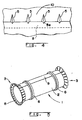
- Fig. 8 illustrates a blanket of material, comprising a porous gasket 19, into which the grout material can be infused.
- the porous gasket can be an open celled plastic material, such as cellulose sponge foam or a polyethylene open-celled foam, or any other material that can absorb a significant quantity of grout, to be explained.
- the primary purpose of the gasket is that of a grout carrier medium. Due to its relatively easy compression transversely, a relatively neglible amount of rebound force is provided by the porous gasket 19 itself against either the sleeve or the inner surface of the conduit under repair.
- the gasket 19 has a width sufficient to extend at least approximately from one flare portion 3 to the other flare portion 3, although this width, as well as the length around the sleeve and thickness of the gasket 19, can be otherwise determined, and is only limited to the extent that an adequate quantity of grout, in the installation position of the sleeve, would be located in the grouting area 12.
- stop elements could be used like those shown in Fig. 6, it is also contemplated that, instead, the outer surfaces of the flare portions could be sealed with a plastic tape 13', extending from a tape roll 13''. If desired the tape can also be used to seal the openings 5b, mentioned above, although little, if any, grouting is found to escape through openings 5b during the installation of the sleeve if they are left open and untaped.
- the gasket 19 is affixed by a contact adhesive or by some appropriate mechanical means, first at one end 20, to the outer surface 2 of the sleeve 1.
- the other end 22 of the gasket 19 is left loose, as illustrated in Fig. 8.
- a thin layer of strengthening material can be applied to the surface of the gasket that would otherwise come in contact with the sleeve.
- the sheet of strengthening material could be made of polyethylene or cellophane or other plastic. The strengthening material could be advantageously placed to the portion of the gasket that will only be sliding upon an adjacent gasket layer and not along the entire length of the gasket.
- the grout could be any of a class of water-reactive types that are commercially available.
- 3M brand 5600 Foam or DeNeef Hydroactive Flex LV can be utilized, the latter with or without a 5% Hydroactive Flex catalyst to speed the time of final installation.
- each roller assembly 23 is affixed to each respective end of the coiled sleeve. As shown in Fig. 9, each roller assembly 23 includes a plug 24 that is inserted into each end of the coiled sleeve. A roller 25 is affixed to each plug 24 for preventing grout from penetrating into the interior of the coiled sleeve and for enabling the coiled sleeve, with gasket thereon, to be rolled in the grout tray 26 by means of handles 27 which project longitudinally from each of the rollers 25.
- the grout tray 26 contains a quantity of grout 28.
- the handles 27 are grasped and slowly rotated about their longitudinal axis, thereby rolling the gasket 19 onto the outer surface 2 of the grouting sleeve 1 and soaking the gasket in the grout 28 contained in the grout tray 26.
- This step is similar in principle to applying paint to a paint roller in a paint tray, with the additional step of rolling the gasket around the sleeve while rotating the handles.
- the sleeve 1 with gasket 19 thereabout is removed from the tray 26.
- the roller assemblies 23 are removed from the ends of the sleeve and, as illustrated in Fig. 9, one or more elastic bands 29 are then placed around the gasket 19 to retain the gasket on the sleeve 1.
- the use of elastic bands 29 is optional. They are utilized merely as a convenience to avoid the inadvertent loosening of the gasket, having just been removed from the grout tray 26.
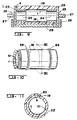
- the grout-impregnated gasket 19/sleeve 1 combination, illustrated in Figs. 10 and 11, in the coiled pre-installation position, is now ready for repair of the damaged and/or leaking conduit or conduit joint.
- Fig. 12 illustrates the approximate quantities of grout needed for three different sleeve lengths and seven different sleeve diameters, in the installed position.
- a means for expanding the sleeve from the coiled pre-installation position to the uncoiled installation position is applied to the gasket/sleeve combination.
- an expandable compressed air-actuable assembly 31 commonly referred to as a "sewer plug”
- a standard unreinforced 5-10B type plug can be used.
- the sewer plug is preferably sprayed with a release agent, such as a silicone spray, prior to insertion into the coiled sleeve. The sewer plug is then expanded enough to "grab" onto the sleeve.
- Fig. 13 schematically illustrates in a cross-sectional elevation view, a location at which a conduit system is being repaired.
- the repair site 30 is part of a conduit system 32, such as a sewer system, extending below ground surface 33.
- Ground surface 33 could comprise a road surface in an urban area, whereby access to the sewer system is had via manholes 34, 35, for example. Since the invention avoids the need for excavation in the repair of the conduit system, the road surface 33 is not destroyed and traffic flow is not significantly interrupted. All materials needed in the repair are transferred through manholes 34, 35.
- the sewer Prior to introduction of the sleeve assembly and associated materials into the sewer system, the sewer is preferably flushed, removing calcite and other debris. The locations of deterioration are inspected and recorded, together with any locations that might pose a problem for passing the sleeve assembly through and, if possible, eliminated. All cables 36, e.g., are prepared and readied in position for pulling the sleeve, sewer plug 31, cctv camera 40, and water line 38 and spray 38a into position. The video camera 40 is utilized to assist the positioning of the assembly and generally to monitor the installation process remotely.
- the sleeve/gasket/air bag assembly i.e., the "sleeve assembly” is located on skid assemblies 39 (or wheeled dollies) or other vehicle to prevent the sleeve from dragging along the invert and to keep it spaced away from any water. It is then transported to the repair site 30.
- the water spray 38a is activated to begin the foaming reaction of the grout.
- the sewer plug is then begun to be inflated at approximately 6.9 kNm -2 S -1 (one psi/sec) to approximately 241 kNm -2 (35 psi).
- the sewer plug is then deflated and the sleeve is locked into the uncoiled installation position.
- the sleeve is locked into the uncoiled installation position.
- the installation is inspected, either manually or via the cctv, to verify that the sleeve has become locked. If the sleeve has not become locked, or if the sleeve has not become completely locked, the sewer plug can again be inflated to accomplish same.
- Figs. 14a - 14d schematically illustrate the steps in moving the sleeve/gasket combination from the coiled pre-installation position to the uncoiled installation position.
- the sewer plug is shown only in Fig. 14a, but is not shown in Figs. 14b - 14d.
- Fig. 14a the sleeve 1 is shown in transport to the repair site, mouted on sewer plug 31.
- the sewer plug supports the sleeve and is mounted on skids 39 via supports 41 that surround the ends of the sewer plug 31.
- sleeve 1 is shown with the gasket 19 thereon, positioned on the bottom of the inside surface lla of the conduit section 11 to be repaired.
- the sleeve/gasket could be located at the site of a joint between two adjacent conduit sections to be sealed.
- the sleeve 1 in Fig. 14b is partially expanded, as depicted in the slightly enlarged internal diameter of sleeve 1 in Fig. 14b.
- the step of applying water can be omitted, permitting the grout to react with the moisture or water resident in the surrounding soil and/or environment at the repair site.
- This latter-mentioned alternative method would lengthen the total process but, however, inasmuch as the sleeve is locked in place by means of the present invention, it would remain secured until the grout completely cures.
- skid assemblies 39 or other vehicle can support the sleeve.
- skid assemblies 39 can be located on either each end of the sleeve beneath end assemblies 41 of the sewer plug during the expansion of the sleeve, to support the sleeve from the lower surface of the conduit section. This ensures that an adequate amount of grout is retained beneath the sleeve in the final installation position of the sleeve and is not squeezed out.
- sleeve 1 is shown in a slightly over-expanded position, a position that is attained prior to the deflation and removal of the air bag.
- the slight over-expansion of the sleeve is necessary to effect the locking of the edge portions of the sleeve, i.e., as mentioned above with regard to Figs. 3 and 4, the locking assembly 5 being located along the length of the sleeve.
- edge region 10 is withdrawn from beneath the members projecting inwardly from edge region 9. Thereafter, upon deflation of the sewer plug, the edge of the edge region 10 is moved toward the coiled position, but is captured by the longitudinally spaced members on edge region 9.
- Fig. 14d illustrates the sleeve in the uncoiled installation position, in which the sleeve 1 has recoiled slightly from the overexpanded position shown in Fig. 14c.
- the complete installation can be performed in as little as thirty minutes.
- Figs. 15-17 schematically illustrate an embodiment in which the sleeve is coated with a layer of thermoplastic material 44.
- the sleeve has perforations 45 within which the thermoplastic layer can flow when heated, thereby fusing adjacent layers of the sleeve when cooled or, alternatively, through which solvents can flow for fusing the adjacent sleeve layers in the final installation position.
- These perforations can be located merely near the edge portions 9' and 10', as shown, or, preferably, they extend throughout the extent of the sleeve.
- projecting "teeth” can be formed in the sleeve, e.g., every 1.9cm (0.75 inches) around the circumference of the sleeve, the sleeve being made of a steel mesh to catch the teeth upon a slight recoil movement.
- the length of the sleeve 1' can be made to be somewhat longer than sleeve 1.
- two overlapping layers of the sleeve are located throughout the circumference thereof, or sustantially throughout the circumference, to facilitate fusing thereof.
- an air bag or sewer plug 31' is provided, similar to sewer plug 31 previously described, but additionally having a heating jacket 42 therearound for the purpose of heating the thermoplastic layer during expansion.
- An outer insulation jacket 43 can be placed around the sewer plug 31' and heating jacket 42 to assist in retaining the heat and to seal the assembly from moisture.
- resistance wires 47 can be embedded within the thermoplastic material so that, upon placement of the sleeve at the site of the conduit section to be repaired, an electrical current is applied, via an electric line, to thereby melt the thermoplastic material, thereby sealing and/or strengthening the damaged and/or weakened conduit section as the heat is removed.
- Fig. 17 schematically illustrates resistance wires 47 embedded in a criss-crossing arrangement within the layer of thermoplastic material 44.
- a non-woven fabric mat made of electrically conductive fibers can be embedded in the layer of thermoplastic material 44 which is then connected to a source of electric current for melting the thermoplastic layer.
- the sleeve could be made to have a shape like that described above with regard to Figs. 15 - 17, but made from PVC, rather than a thermoplastic coated material, whereby, upon inflation of the sleeve to the uncoiled installation position, a solvent, such as toluene or other aromatic hydrocarbon, is applied to the sleeve, upon expansion of the sleeve, flowing along the surface of the sleeve, through openings thereof, thereby partially dissolving overlapping layers, fusing same upon evaporation of the solvent.
- a solvent such as toluene or other aromatic hydrocarbon
- the sleeve could be made of polyethylene.
- the heat could be applied only to the areas of overlap of the edge regions.
- the resistance wires could be embedded for less than the entire length around the circumference of the sleeve, that is, only locally at areas of overlap. Further, the openings or perforations in the sleeve could be also only localized at areas of overlap.
- thermoplastic or solvent fusing for example, a locking arrangement like that described above, can be omitted, together with the need to over-expand the sleeve to effect the locking. Thus, even less pressure from the sewer plug is needed to complete the installation.
- sleeve fusion embodiments can be used in place of other sleeve embodiments generally known, or they can be used in conjunction with certain of the features of other embodiments of the repair apparatus, previously described.
- a grout is located in a grouting area, in the manner described in the preceding embodiments of the invention. That is, stop elements, flared end portions attached to the sleeve, are utilized in the manner described above.
- the sleeve 1 is shown to have a flare portion on each end. It is also contemplated that only one of the ends can be flared for length-wise attachment to previously installed sleeves for the purpose of providing continuous repairs for longer lengths, for example.
Landscapes
- Engineering & Computer Science (AREA)
- General Engineering & Computer Science (AREA)
- Mechanical Engineering (AREA)
- Pipe Accessories (AREA)
- Application Of Or Painting With Fluid Materials (AREA)
- Earth Drilling (AREA)
Applications Claiming Priority (3)
| Application Number | Priority Date | Filing Date | Title |
|---|---|---|---|
| US849217 | 1992-03-10 | ||
| US07/849,217 US5351720A (en) | 1992-03-10 | 1992-03-10 | Apparatus for repairing conduits |
| PCT/CA1993/000086 WO1993018334A1 (en) | 1992-03-10 | 1993-03-09 | Method and apparatus for repairing conduits |
Publications (2)
| Publication Number | Publication Date |
|---|---|
| EP0630458A1 EP0630458A1 (en) | 1994-12-28 |
| EP0630458B1 true EP0630458B1 (en) | 1997-09-17 |
Family
ID=25305331
Family Applications (1)
| Application Number | Title | Priority Date | Filing Date |
|---|---|---|---|
| EP93906413A Expired - Lifetime EP0630458B1 (en) | 1992-03-10 | 1993-03-09 | Method and apparatus for repairing conduits |
Country Status (12)
| Country | Link |
|---|---|
| US (1) | US5351720A (da) |
| EP (1) | EP0630458B1 (da) |
| JP (1) | JPH07507125A (da) |
| AT (1) | ATE158392T1 (da) |
| AU (1) | AU672784B2 (da) |
| CA (1) | CA2131291C (da) |
| DE (1) | DE69314011T2 (da) |
| DK (1) | DK0630458T3 (da) |
| ES (1) | ES2109480T3 (da) |
| HK (1) | HK1003143A1 (da) |
| SG (1) | SG48966A1 (da) |
| WO (1) | WO1993018334A1 (da) |
Cited By (1)
| Publication number | Priority date | Publication date | Assignee | Title |
|---|---|---|---|---|
| EP0867653A1 (de) | 1997-03-27 | 1998-09-30 | Rainer Roos | Sanierungsschale für Rohrleitungen |
Families Citing this family (70)
| Publication number | Priority date | Publication date | Assignee | Title |
|---|---|---|---|---|
| WO1995015460A1 (de) * | 1993-12-02 | 1995-06-08 | Helmar Haas | Sanierungselement für kanäle, drainage-deponierrohre und dgl. |
| ES2119038T3 (es) * | 1993-12-03 | 1998-10-01 | Uhrig Kanaltechnik Gmbh | Dispositivo para la estanqueidad de fugas internas de tubos y procedimiento de estanqueidad de fugas. |
| WO1996016790A1 (en) * | 1994-12-02 | 1996-06-06 | Sure Grip North America, L.L.C. | A lining system and method for installing a plastic liner |
| ATE199675T1 (de) * | 1995-06-26 | 2001-03-15 | Nextrom Holding Sa | Extrusionsvorrichtung, tubenförmiger gegenstand und rohr |
| US5967192A (en) * | 1995-08-04 | 1999-10-19 | Kanal Technik Ingenieurburo | Process and device for refurbishing drains |
| TW347455B (en) * | 1995-11-09 | 1998-12-11 | Link Pipe Inc | Conduit lining system and method of lining a conduit |
| DE19610477A1 (de) * | 1996-03-16 | 1997-09-18 | Rico Mikroelektronik Gmbh | Aufweitbare Schale zur innenseitigen Kanalrohrsanierung |
| DE29806603U1 (de) * | 1998-04-09 | 1998-07-23 | Hecht, Reinhard, 93167 Falkenstein | Dichtelement zur Abdichtung von Rohrleitungen |
| US6240965B1 (en) | 1998-04-24 | 2001-06-05 | Link-Pipe (H.K.), Ltd. | Apparatus for repair of high temperature and pressure conduits, method for repairing high temperature and pressure conduits, and a sealing device for repairing high temperature and pressure conduits |
| US6138718A (en) * | 1998-10-30 | 2000-10-31 | Link-Pipe (H. K.), Ltd. | Apparatus and method for repairing pressure pipes |
| US6095197A (en) * | 1999-10-11 | 2000-08-01 | Cascade Waterworks Manufacturing Co., Inc. | Pipe coupling stiffener |
| AU770050B2 (en) * | 2000-01-31 | 2004-02-12 | Alois Gruber Gmbh | Synthetic panel, especially for lining concrete building components |
| US6569283B1 (en) * | 2000-03-15 | 2003-05-27 | Sealed Air Corporation (Us) | Inflator/sealer device for inflatable packaging cushion |
| US6276532B1 (en) | 2000-03-15 | 2001-08-21 | Sealed Air Corporation (Us) | Inflatable packaging cushion with a resistance wire |
| WO2001075269A2 (en) | 2000-03-31 | 2001-10-11 | Link Pipe, Inc. | Tunnel lining apparatus and method |
| GB2373830B (en) * | 2001-03-30 | 2004-05-26 | Price Brothers | A method of repairing a prestressed concrete pipe |
| US7004681B2 (en) * | 2001-05-18 | 2006-02-28 | Penza G Gregory | Method and apparatus for routing cable in existing pipelines |
| US6712556B2 (en) | 2001-05-18 | 2004-03-30 | G. Gregory Penza | Method and apparatus for routing cable in existing pipelines |
| US20030175520A1 (en) * | 2002-03-13 | 2003-09-18 | Grutta James T. | Formed composite structural members and methods and apparatus for making the same |
| US20030173715A1 (en) * | 2002-03-13 | 2003-09-18 | Grutta James T. | Resistive-heated composite structural members and methods and apparatus for making the same |
| MXPA05004590A (es) | 2002-10-30 | 2005-09-12 | J R Pipeline Co Inc | Aparato y metodo para la instalacion de revestimiento de tuberias. |
| US6973969B2 (en) * | 2003-08-08 | 2005-12-13 | Halliburton Energy Services, Inc. | Apparatus and methods for preventing or limiting rotation of cementing plugs |
| US20050173115A1 (en) * | 2004-02-06 | 2005-08-11 | Link-Pipe, Inc. | Apparatus and method for repair of underground conduits |
| KR20050098689A (ko) * | 2004-04-08 | 2005-10-12 | 주식회사 케이티 | 통신관로 부분보수용 슬리브 |
| DE112006000575T5 (de) * | 2005-03-16 | 2008-01-24 | Hangangcc Co. Ltd., Namyangju | Material zur aushubfreien Reparatur eines Rohrs und Reparaturverfahren |
| FI119658B (fi) * | 2005-06-10 | 2009-01-30 | Kwh Pipe Ab Oy | Taloliittymämoduuli ja menetelmä sen valmistamiseksi |
| DE102005048689B3 (de) * | 2005-10-11 | 2007-05-03 | Uhrig Kanaltechnik Gmbh | Wärmetauscher zur Abwasserwärmenutzung |
| US7905255B2 (en) * | 2006-08-28 | 2011-03-15 | Iwasaki-Higbee Jeffrey L | Installation of sealant materials for repair of underground conduits |
| US7896032B2 (en) * | 2006-09-28 | 2011-03-01 | Lmk Enterprises, Inc. | Method and device for lining pipe |
| MX2010001463A (es) * | 2007-08-07 | 2010-06-01 | Allan Cecil Goldring | Dispositivo para prevencion de robo de cables. |
| AT506932B1 (de) * | 2008-05-19 | 2010-03-15 | Kuebel Johann Ing | Verfahren zum abdichten eines rohrabschnittes |
| US9052051B2 (en) * | 2009-04-20 | 2015-06-09 | Link-Pipe, Inc. | Apparatus and method for internal repair of conduits |
| US20100282408A1 (en) * | 2009-05-07 | 2010-11-11 | Kuipers Kirk E | Method and device for lining a pipe |
| US8186385B2 (en) * | 2009-07-06 | 2012-05-29 | Iwasaki-Higbee Jeffrey L | Packer for installing sealant in defective conduits |
| US9568139B2 (en) * | 2010-02-26 | 2017-02-14 | Trelleborg Pipe Seals Duisburg Gmbh | Lining element and method of manufacturing a lining element |
| US9689522B2 (en) * | 2010-02-26 | 2017-06-27 | Trelleborg Pipe Seals Duisburg Gmbh | Lining element, and method of manufacturing a lining element |
| US9551449B2 (en) * | 2010-05-26 | 2017-01-24 | Lmk Technologies, Llc | Method for creating a seal between pipe liners |
| CA140497S (en) * | 2011-05-06 | 2013-12-23 | Richard A Tools Co Outils Richard A Co | Plug for paint roller cover |
| DE202012012667U1 (de) * | 2012-11-23 | 2013-08-09 | GRAF Patentverwertungs GbR (vertretungsberechtigte Gesellschafter: Jürgen Graf, 78073 Bad Dürrheim, Joachim Graf, 78073 Bad Dürrheim) | Dichtungsinnenmanschette mit verbessertem Arretierungsmechanismus |
| CN103216204B (zh) * | 2013-04-28 | 2015-07-15 | 成都科盛石油科技有限公司 | 用于修复油水井内凹套管的工装 |
| US20160146396A1 (en) * | 2014-11-26 | 2016-05-26 | Smart Lock Pty Ltd. | Expandable Pipeline Point-Repair Device |
| JP5903178B1 (ja) * | 2015-03-31 | 2016-04-13 | 関東天然瓦斯開発株式会社 | 円管及び立坑の内壁への被覆部材の取付方法 |
| US9945505B2 (en) * | 2015-05-15 | 2018-04-17 | Lmk Technologies, Llc | Method and apparatus for repairing a pipe using a transition tube |
| EP3239584A1 (en) * | 2016-04-28 | 2017-11-01 | 3M Innovative Properties Company | Method of sealing a pipe |
| DE102016006561B4 (de) * | 2016-05-25 | 2022-07-28 | Uhrig Kanaltechnik Gmbh | Dichtungsmanschette für Rohrversätze |
| US10605398B2 (en) * | 2017-02-06 | 2020-03-31 | Stress Engineering Services, Inc. | Remotely controlled pipeline section internal repair device and installation method |
| US20180266416A1 (en) | 2017-03-20 | 2018-09-20 | Recyca-Pipe Of America L.L.C. | Grouting material delivery and application system |
| RU2677913C1 (ru) | 2017-10-02 | 2019-01-22 | Александр Георгиевич Чуйко | Устройство Чуйко для внутренней монолитной изоляции сварного соединения трубопровода (варианты) |
| US10641427B2 (en) | 2018-04-03 | 2020-05-05 | Mueller International, Llc | Stents and methods for repairing pipes |
| WO2019239298A1 (en) * | 2018-06-11 | 2019-12-19 | Link-Pipe, Inc. | Trenchless mechanical lining apparatus for continuous repair of underground pipes and culverts, and method of installation |
| EP3928022B1 (en) | 2019-02-19 | 2025-01-29 | Mueller International, LLC | Stent springs and stents for repairing pipes |
| CN111664314A (zh) * | 2019-03-08 | 2020-09-15 | 上海宇联给水工程有限公司 | 不锈钢胀环堵漏节 |
| US11079058B2 (en) | 2019-03-15 | 2021-08-03 | Mueller International , LLC | Stent with coiled spring |
| US11187366B2 (en) | 2019-03-15 | 2021-11-30 | Mueller International, Llc | Stent for repairing a pipe |
| US11326731B2 (en) | 2019-04-24 | 2022-05-10 | Mueller International, Llc | Pipe repair assembly |
| CN110425376B (zh) * | 2019-08-07 | 2020-09-08 | 武汉理工大学 | 一种管道泄漏监测及应急堵漏装置 |
| US11391405B2 (en) | 2019-08-09 | 2022-07-19 | Mueller International, Llc | Deployment probe for pipe repair device |
| US11802646B2 (en) | 2019-08-09 | 2023-10-31 | Mueller International, Llc | Pipe repair device |
| CN110645440A (zh) * | 2019-09-25 | 2020-01-03 | 郑州大学 | 用于大管径混凝土排水管脱节的非开挖修复装置及方法 |
| EP4038304B1 (de) * | 2019-10-01 | 2025-07-02 | Pipetronics GmbH & Co. KG | Vorabdichtung vor dem sanieren einer leitung |
| BR112022018077A2 (pt) * | 2020-03-23 | 2022-10-25 | Isealate As | Ferramenta de assentamento para um aparelho de fundo de poço para reparar uma parede de um conduto e um método de reparar um conduto |
| CA3112125C (en) * | 2021-03-17 | 2022-10-04 | Hc Properties Inc. | Support structure and method of forming a support structure |
| CN113063052A (zh) * | 2021-03-17 | 2021-07-02 | 中核四平市政工程有限公司 | 一种管道内衬注浆修复方法 |
| CN114941760B (zh) * | 2022-05-13 | 2024-07-16 | 广东华士特威石油工程设备有限公司 | 一种石油管道堵漏装置 |
| CN115404968B (zh) * | 2022-10-13 | 2025-06-13 | 中国安能集团第一工程局有限公司 | 一种不锈钢快速锁修复管道装置及施工方法 |
| US20240175534A1 (en) * | 2022-11-30 | 2024-05-30 | Mueller International, Llc | Pipe repair stent with structural chassis |
| US12492550B2 (en) * | 2023-04-18 | 2025-12-09 | Dupont Safety & Construction, Inc. | Foam envelope for sealing large volumes |
| US12492551B2 (en) * | 2023-04-18 | 2025-12-09 | Dupont Safety & Construction, Inc. | Foam envelope for sealing large volumes |
| US12454822B2 (en) * | 2023-04-18 | 2025-10-28 | Ddp Specialty Electronic Materials Us, Llc | Foam envelope for sealing large volumes |
| US12559935B2 (en) * | 2023-04-18 | 2026-02-24 | Dupont Safety & Construction, Inc. | Foam envelope for sealing large volumes |
Family Cites Families (27)
| Publication number | Priority date | Publication date | Assignee | Title |
|---|---|---|---|---|
| US646804A (en) * | 1899-11-13 | 1900-04-03 | Marcellus Miller | Boiler-tube stopper. |
| US1301285A (en) * | 1916-09-01 | 1919-04-22 | Frank W A Finley | Expansible well-casing. |
| US2583316A (en) * | 1947-12-09 | 1952-01-22 | Clyde E Bannister | Method and apparatus for setting a casing structure in a well hole or the like |
| US2977994A (en) * | 1957-12-26 | 1961-04-04 | Cons Edison Co New York Inc | Method and apparatus for sealing pipe joints |
| US3678560A (en) * | 1970-05-06 | 1972-07-25 | Northern Illinois Gas Co | Internal pipe sealing system |
| US3700265A (en) * | 1972-02-04 | 1972-10-24 | Northern Illinois Gas Co | Internal pipe sealing device |
| US3834422A (en) * | 1973-01-19 | 1974-09-10 | Cherne Ind Inc | Sewer repair apparatus |
| US3946761A (en) * | 1974-06-24 | 1976-03-30 | The Penetryn System, Inc. | Packer for sealing pipe leaks |
| GB1594573A (en) * | 1976-11-05 | 1981-07-30 | Raychem Sa Nv | Sealing and insulating heat-recoverable article and method |
| US4124985A (en) * | 1977-09-28 | 1978-11-14 | Lembit Maimets | Collapsible tunnel liner section and method of lining a tunnel |
| USRE30929E (en) * | 1977-09-28 | 1982-05-11 | Collapsible tunnel liner section and method of lining a tunnel | |
| IE49962B1 (en) * | 1979-08-09 | 1986-01-22 | Johnston Constr Ltd | Lining or relining of tunnels |
| US4346922A (en) * | 1980-03-21 | 1982-08-31 | Hisao Ohtsuga | Device for preventing leakage at pipe joints |
| FR2480901B1 (fr) * | 1980-04-18 | 1985-10-11 | Coopetanche Sa | Procede de garnissage interne d'une conduite |
| GB2136912A (en) * | 1983-03-16 | 1984-09-26 | Michael Francis Barry | Sealing pipes |
| EP0159300A1 (en) * | 1984-03-30 | 1985-10-23 | Stig Westman | Repair sleeve for piping |
| US4602659A (en) * | 1984-04-16 | 1986-07-29 | William A. Parkyn, Sr. | Repair in holes and cracks in clay sewer pipe |
| DE8707049U1 (de) * | 1987-05-15 | 1987-07-02 | Riezler, Josef, 8985 Hirschegg | Einrichtung zum Abdichten lokaler Leckstellen in Rohrleitungen |
| US4956032A (en) * | 1988-04-28 | 1990-09-11 | Keller Industries Ltd. | Method of grouting using a vacuum |
| JP2719831B2 (ja) * | 1988-10-31 | 1998-02-25 | リンク―パイプ テクノロジーズ インコーポレイテッド | 管補修のためのスリーブ、ライナー、装置および方法 |
| US5119862A (en) * | 1988-10-31 | 1992-06-09 | Link-Pipe Technlogies, Inc. | Conduit repair apparatus |
| US5042532A (en) * | 1989-08-01 | 1991-08-27 | Cues, Inc. | Expandable tube apparatus for repairing pipelines |
| AU630482B2 (en) * | 1989-08-14 | 1992-10-29 | Kabushiki Kaisha Iseki Kaihatsu Koki | Liner for pipeline repair and method for repairing pipelines |
| JPH0830555B2 (ja) * | 1989-08-15 | 1996-03-27 | 東亜グラウト工業株式会社 | 管路の漏水防止方法および漏水防止用被覆体 |
| US4995761A (en) * | 1989-08-23 | 1991-02-26 | Barton Kenneth S | Method and apparatus for repairing ruptures in underground conduits |
| US5049003A (en) * | 1989-08-23 | 1991-09-17 | Kenneth Barton | Method and apparatus for repairing ruptures in underground conduits |
| KR970001692B1 (ko) * | 1990-02-15 | 1997-02-13 | 신기찌 오오까 | 관로의 지수방법과 관로의 연결부 구조체 및 지수재 |
-
1992
- 1992-03-10 US US07/849,217 patent/US5351720A/en not_active Expired - Lifetime
-
1993
- 1993-03-09 WO PCT/CA1993/000086 patent/WO1993018334A1/en not_active Ceased
- 1993-03-09 SG SG1996004369A patent/SG48966A1/en unknown
- 1993-03-09 AU AU37429/93A patent/AU672784B2/en not_active Ceased
- 1993-03-09 DE DE69314011T patent/DE69314011T2/de not_active Expired - Fee Related
- 1993-03-09 JP JP5515202A patent/JPH07507125A/ja active Pending
- 1993-03-09 EP EP93906413A patent/EP0630458B1/en not_active Expired - Lifetime
- 1993-03-09 HK HK98101981A patent/HK1003143A1/en not_active IP Right Cessation
- 1993-03-09 CA CA002131291A patent/CA2131291C/en not_active Expired - Lifetime
- 1993-03-09 AT AT93906413T patent/ATE158392T1/de not_active IP Right Cessation
- 1993-03-09 DK DK93906413.5T patent/DK0630458T3/da active
- 1993-03-09 ES ES93906413T patent/ES2109480T3/es not_active Expired - Lifetime
Cited By (1)
| Publication number | Priority date | Publication date | Assignee | Title |
|---|---|---|---|---|
| EP0867653A1 (de) | 1997-03-27 | 1998-09-30 | Rainer Roos | Sanierungsschale für Rohrleitungen |
Also Published As
| Publication number | Publication date |
|---|---|
| JPH07507125A (ja) | 1995-08-03 |
| WO1993018334A1 (en) | 1993-09-16 |
| DK0630458T3 (da) | 1998-05-11 |
| AU3742993A (en) | 1993-10-05 |
| EP0630458A1 (en) | 1994-12-28 |
| ATE158392T1 (de) | 1997-10-15 |
| DE69314011D1 (de) | 1997-10-23 |
| DE69314011T2 (de) | 1998-04-16 |
| HK1003143A1 (en) | 1998-10-09 |
| ES2109480T3 (es) | 1998-01-16 |
| US5351720A (en) | 1994-10-04 |
| SG48966A1 (en) | 1998-05-18 |
| AU672784B2 (en) | 1996-10-17 |
| CA2131291A1 (en) | 1993-09-16 |
| CA2131291C (en) | 2004-05-04 |
Similar Documents
| Publication | Publication Date | Title |
|---|---|---|
| EP0630458B1 (en) | Method and apparatus for repairing conduits | |
| HK1003143B (en) | Method and apparatus for repairing conduits | |
| US5186215A (en) | Apparatus for repairing pipelines | |
| US5042532A (en) | Expandable tube apparatus for repairing pipelines | |
| US4049480A (en) | Method and apparatus for forming a joint in a confined space between two abutting ends of conduit liners | |
| CA2173127C (en) | Method and apparatus for repairing a pipeline | |
| US5096206A (en) | Pipe joint sealer | |
| US4162093A (en) | Heat-insulated pipe-lines | |
| US6021815A (en) | Method for preparing a repair assembly for pipe repair | |
| CA2790704C (en) | Apparatus and method to repair the junction of a sewer main line and lateral pipe | |
| ES2343185T3 (es) | Revestimiento endurecido en el lugar con capa impermeable interior integral y metodo continuo de fabricacion. | |
| IE71184B1 (en) | Improvements in methods for installing a substantially rigid thermoplastic pipe in an existing conduit | |
| US20040173272A1 (en) | Reinforcing element of underground pipe, and trenchless repairing and reinforcing method using the same | |
| US4752431A (en) | Permanent conforming pipe for conducting fluids and the like and method for producing the same | |
| CA2365665C (en) | Method and installation for laying a cylindrical pipe on a support | |
| KR101480260B1 (ko) | 하수관 부분 보수 장치 및 공법 | |
| EP0216766B1 (en) | A permanent conforming pipe for conducting fluids and the like and method for producing the same | |
| US20100237606A1 (en) | End seal for pipeline | |
| JP3691880B2 (ja) | 管路の補修用被覆体 | |
| EP1426671A1 (en) | Method for using a lateral liner and main liner to repair pipeline | |
| JPH08109672A (ja) | 既設管渠における継目部の更生工法及びその工法に使用する更生用被覆体 | |
| JP3188943B2 (ja) | 地中管補修方法 | |
| Koerner et al. | Geosynthetic use in trenchless pipe remediation and rehabilitation | |
| AU742515B2 (en) | Apparatus for repairing a pipeline and method for using same | |
| JP3165227B2 (ja) | 管路の内張り材 |
Legal Events
| Date | Code | Title | Description |
|---|---|---|---|
| PUAI | Public reference made under article 153(3) epc to a published international application that has entered the european phase |
Free format text: ORIGINAL CODE: 0009012 |
|
| 17P | Request for examination filed |
Effective date: 19941004 |
|
| AK | Designated contracting states |
Kind code of ref document: A1 Designated state(s): AT BE CH DE DK ES FR GB GR IE IT LI LU MC NL PT SE |
|
| 17Q | First examination report despatched |
Effective date: 19960103 |
|
| GRAG | Despatch of communication of intention to grant |
Free format text: ORIGINAL CODE: EPIDOS AGRA |
|
| GRAH | Despatch of communication of intention to grant a patent |
Free format text: ORIGINAL CODE: EPIDOS IGRA |
|
| GRAH | Despatch of communication of intention to grant a patent |
Free format text: ORIGINAL CODE: EPIDOS IGRA |
|
| GRAA | (expected) grant |
Free format text: ORIGINAL CODE: 0009210 |
|
| AK | Designated contracting states |
Kind code of ref document: B1 Designated state(s): AT BE CH DE DK ES FR GB GR IE IT LI LU MC NL PT SE |
|
| PG25 | Lapsed in a contracting state [announced via postgrant information from national office to epo] |
Ref country code: IT Free format text: LAPSE BECAUSE OF FAILURE TO SUBMIT A TRANSLATION OF THE DESCRIPTION OR TO PAY THE FEE WITHIN THE PRESCRIBED TIME-LIMIT;WARNING: LAPSES OF ITALIAN PATENTS WITH EFFECTIVE DATE BEFORE 2007 MAY HAVE OCCURRED AT ANY TIME BEFORE 2007. THE CORRECT EFFECTIVE DATE MAY BE DIFFERENT FROM THE ONE RECORDED. Effective date: 19970917 Ref country code: GR Free format text: LAPSE BECAUSE OF FAILURE TO SUBMIT A TRANSLATION OF THE DESCRIPTION OR TO PAY THE FEE WITHIN THE PRESCRIBED TIME-LIMIT Effective date: 19970917 Ref country code: AT Effective date: 19970917 |
|
| REF | Corresponds to: |
Ref document number: 158392 Country of ref document: AT Date of ref document: 19971015 Kind code of ref document: T |
|
| REG | Reference to a national code |
Ref country code: CH Ref legal event code: EP |
|
| REF | Corresponds to: |
Ref document number: 69314011 Country of ref document: DE Date of ref document: 19971023 |
|
| PG25 | Lapsed in a contracting state [announced via postgrant information from national office to epo] |
Ref country code: PT Effective date: 19971217 |
|
| REG | Reference to a national code |
Ref country code: CH Ref legal event code: NV Representative=s name: PATENTANWAELTE SCHAAD, BALASS, MENZL & PARTNER AG |
|
| REG | Reference to a national code |
Ref country code: ES Ref legal event code: FG2A Ref document number: 2109480 Country of ref document: ES Kind code of ref document: T3 |
|
| ET | Fr: translation filed | ||
| REG | Reference to a national code |
Ref country code: IE Ref legal event code: FG4D Free format text: 76525 |
|
| PG25 | Lapsed in a contracting state [announced via postgrant information from national office to epo] |
Ref country code: LU Free format text: LAPSE BECAUSE OF NON-PAYMENT OF DUE FEES Effective date: 19980309 Ref country code: IE Free format text: LAPSE BECAUSE OF NON-PAYMENT OF DUE FEES Effective date: 19980309 |
|
| REG | Reference to a national code |
Ref country code: DK Ref legal event code: T3 |
|
| PLBE | No opposition filed within time limit |
Free format text: ORIGINAL CODE: 0009261 |
|
| STAA | Information on the status of an ep patent application or granted ep patent |
Free format text: STATUS: NO OPPOSITION FILED WITHIN TIME LIMIT |
|
| 26N | No opposition filed | ||
| PG25 | Lapsed in a contracting state [announced via postgrant information from national office to epo] |
Ref country code: MC Free format text: LAPSE BECAUSE OF NON-PAYMENT OF DUE FEES Effective date: 19980930 |
|
| REG | Reference to a national code |
Ref country code: GB Ref legal event code: IF02 |
|
| PGFP | Annual fee paid to national office [announced via postgrant information from national office to epo] |
Ref country code: NL Payment date: 20050303 Year of fee payment: 13 |
|
| PGFP | Annual fee paid to national office [announced via postgrant information from national office to epo] |
Ref country code: SE Payment date: 20050304 Year of fee payment: 13 Ref country code: DE Payment date: 20050304 Year of fee payment: 13 |
|
| PGFP | Annual fee paid to national office [announced via postgrant information from national office to epo] |
Ref country code: FR Payment date: 20050308 Year of fee payment: 13 |
|
| PGFP | Annual fee paid to national office [announced via postgrant information from national office to epo] |
Ref country code: GB Payment date: 20050309 Year of fee payment: 13 |
|
| PGFP | Annual fee paid to national office [announced via postgrant information from national office to epo] |
Ref country code: DK Payment date: 20050314 Year of fee payment: 13 |
|
| PGFP | Annual fee paid to national office [announced via postgrant information from national office to epo] |
Ref country code: CH Payment date: 20050316 Year of fee payment: 13 |
|
| PGFP | Annual fee paid to national office [announced via postgrant information from national office to epo] |
Ref country code: ES Payment date: 20050425 Year of fee payment: 13 |
|
| PGFP | Annual fee paid to national office [announced via postgrant information from national office to epo] |
Ref country code: BE Payment date: 20050509 Year of fee payment: 13 |
|
| PG25 | Lapsed in a contracting state [announced via postgrant information from national office to epo] |
Ref country code: GB Free format text: LAPSE BECAUSE OF NON-PAYMENT OF DUE FEES Effective date: 20060309 |
|
| PG25 | Lapsed in a contracting state [announced via postgrant information from national office to epo] |
Ref country code: SE Free format text: LAPSE BECAUSE OF NON-PAYMENT OF DUE FEES Effective date: 20060310 Ref country code: ES Free format text: LAPSE BECAUSE OF NON-PAYMENT OF DUE FEES Effective date: 20060310 |
|
| PG25 | Lapsed in a contracting state [announced via postgrant information from national office to epo] |
Ref country code: LI Free format text: LAPSE BECAUSE OF NON-PAYMENT OF DUE FEES Effective date: 20060331 Ref country code: DK Free format text: LAPSE BECAUSE OF NON-PAYMENT OF DUE FEES Effective date: 20060331 Ref country code: CH Free format text: LAPSE BECAUSE OF NON-PAYMENT OF DUE FEES Effective date: 20060331 Ref country code: BE Free format text: LAPSE BECAUSE OF NON-PAYMENT OF DUE FEES Effective date: 20060331 |
|
| PG25 | Lapsed in a contracting state [announced via postgrant information from national office to epo] |
Ref country code: NL Free format text: LAPSE BECAUSE OF NON-PAYMENT OF DUE FEES Effective date: 20061001 |
|
| PG25 | Lapsed in a contracting state [announced via postgrant information from national office to epo] |
Ref country code: DE Free format text: LAPSE BECAUSE OF NON-PAYMENT OF DUE FEES Effective date: 20061003 |
|
| REG | Reference to a national code |
Ref country code: DK Ref legal event code: EBP |
|
| REG | Reference to a national code |
Ref country code: CH Ref legal event code: PL |
|
| EUG | Se: european patent has lapsed | ||
| GBPC | Gb: european patent ceased through non-payment of renewal fee |
Effective date: 20060309 |
|
| NLV4 | Nl: lapsed or anulled due to non-payment of the annual fee |
Effective date: 20061001 |
|
| REG | Reference to a national code |
Ref country code: FR Ref legal event code: ST Effective date: 20061130 |
|
| REG | Reference to a national code |
Ref country code: ES Ref legal event code: FD2A Effective date: 20060310 |
|
| BERE | Be: lapsed |
Owner name: *LINK-PIPE INC. Effective date: 20060331 |
|
| PG25 | Lapsed in a contracting state [announced via postgrant information from national office to epo] |
Ref country code: FR Free format text: LAPSE BECAUSE OF NON-PAYMENT OF DUE FEES Effective date: 20060331 |