EP0630585A1 - Procédé et dispositif de contrôle de la résistance à l'aspiration des tiges de filtres - Google Patents
Procédé et dispositif de contrôle de la résistance à l'aspiration des tiges de filtres Download PDFInfo
- Publication number
- EP0630585A1 EP0630585A1 EP94107087A EP94107087A EP0630585A1 EP 0630585 A1 EP0630585 A1 EP 0630585A1 EP 94107087 A EP94107087 A EP 94107087A EP 94107087 A EP94107087 A EP 94107087A EP 0630585 A1 EP0630585 A1 EP 0630585A1
- Authority
- EP
- European Patent Office
- Prior art keywords
- pressure
- article
- measuring
- tensile resistance
- measuring chamber
- Prior art date
- Legal status (The legal status is an assumption and is not a legal conclusion. Google has not performed a legal analysis and makes no representation as to the accuracy of the status listed.)
- Ceased
Links
- 238000012360 testing method Methods 0.000 title claims abstract description 31
- 238000000034 method Methods 0.000 title claims abstract description 28
- 238000005259 measurement Methods 0.000 claims abstract description 32
- 238000012545 processing Methods 0.000 claims abstract description 9
- 241000208125 Nicotiana Species 0.000 claims abstract description 7
- 235000002637 Nicotiana tabacum Nutrition 0.000 claims abstract description 7
- 238000004519 manufacturing process Methods 0.000 claims description 21
- 238000011156 evaluation Methods 0.000 claims description 14
- 238000009530 blood pressure measurement Methods 0.000 claims description 9
- 238000007789 sealing Methods 0.000 claims description 5
- 230000002123 temporal effect Effects 0.000 claims description 4
- 238000012546 transfer Methods 0.000 claims description 3
- 238000003780 insertion Methods 0.000 claims description 2
- 230000037431 insertion Effects 0.000 claims description 2
- 238000012432 intermediate storage Methods 0.000 claims description 2
- 235000019504 cigarettes Nutrition 0.000 description 11
- 238000011161 development Methods 0.000 description 3
- 230000018109 developmental process Effects 0.000 description 3
- 238000010586 diagram Methods 0.000 description 3
- 238000007664 blowing Methods 0.000 description 2
- 238000013461 design Methods 0.000 description 2
- 230000001105 regulatory effect Effects 0.000 description 2
- 230000004323 axial length Effects 0.000 description 1
- 230000033228 biological regulation Effects 0.000 description 1
- 230000001419 dependent effect Effects 0.000 description 1
- 239000012528 membrane Substances 0.000 description 1
- 230000035699 permeability Effects 0.000 description 1
- 238000011144 upstream manufacturing Methods 0.000 description 1
- 238000009423 ventilation Methods 0.000 description 1
- 230000037303 wrinkles Effects 0.000 description 1
Images
Classifications
-
- A—HUMAN NECESSITIES
- A24—TOBACCO; CIGARS; CIGARETTES; SIMULATED SMOKING DEVICES; SMOKERS' REQUISITES
- A24C—MACHINES FOR MAKING CIGARS OR CIGARETTES
- A24C5/00—Making cigarettes; Making tipping materials for, or attaching filters or mouthpieces to, cigars or cigarettes
- A24C5/32—Separating, ordering, counting or examining cigarettes; Regulating the feeding of tobacco according to rod or cigarette condition
- A24C5/34—Examining cigarettes or the rod, e.g. for regulating the feeding of tobacco; Removing defective cigarettes
- A24C5/3418—Examining cigarettes or the rod, e.g. for regulating the feeding of tobacco; Removing defective cigarettes by pneumatic means
-
- G—PHYSICS
- G01—MEASURING; TESTING
- G01N—INVESTIGATING OR ANALYSING MATERIALS BY DETERMINING THEIR CHEMICAL OR PHYSICAL PROPERTIES
- G01N15/00—Investigating characteristics of particles; Investigating permeability, pore-volume or surface-area of porous materials
- G01N15/08—Investigating permeability, pore-volume, or surface area of porous materials
- G01N15/082—Investigating permeability by forcing a fluid through a sample
- G01N15/0826—Investigating permeability by forcing a fluid through a sample and measuring fluid flow rate, i.e. permeation rate or pressure change
Definitions
- the invention relates to a method and a device for measuring the tensile resistance of filter rods or other rod-shaped articles of the tobacco processing industry.
- the draw resistance is an important quality criterion of cigarettes and other smokable articles, which the smoker immediately perceives and decisively shapes his impression of the product.
- the draw resistance of filter cigarettes is largely influenced by the draw resistance of the filter section. It is therefore of crucial importance for the production of products or articles that are qualitatively acceptable in this respect to provide filter sections or filter rods with defined and as constant as possible tensile resistance. There is therefore a desire and need to measure the tensile resistance of filter rods before they are further processed, if possible during their manufacture, in order to be able to intervene in the filter manufacturing process in the sense of producing filter rods with constant tensile resistances.
- the invention has for its object to provide a method and an apparatus for measuring the tensile resistance of filter rods or other rod-shaped articles of the tobacco processing industry, which also meet high requirements for uniqueness, accuracy and reproducibility and which are used economically in the manufacture of articles for tension resistance control can be.
- this object is achieved according to the invention in that an article is positioned in a measuring chamber and its covering is sealed from the outside, that a pressure which differs from the ambient pressure is applied to one end of the article, that a pressure is applied by the Article caused pressure drop is measured and that a test signal representing the tensile resistance of the article is generated from the pressure measurement.
- a certain initial pressure is applied to an article end and a corresponding air flow is started through the article. At least two pressure measurements are carried out in succession and corresponding measurement signals are formed. The measurement signals are processed into a test signal representing the tensile resistance.
- an initial pressure different from the ambient pressure is built up in a pressure volume, that the pressure volume is connected to one end of the measuring chamber and the initial pressure is reduced through the article positioned therein, that at least two pressure measurements are carried out in succession and corresponding measurement signals are formed that the temporal course of the change in the initial pressure is determined from the chronological sequence and the size of the measurement signals and that the tensile resistance of the article is determined from the temporal course of the pressure change and a corresponding test signal is generated.
- the invention thus provides a new method for determining the pulling resistance of cigarettes or filter rods, in which a pressure built up in a pressure chamber is reduced through the article after the connection of the pressure container to the pressure source has been interrupted.
- the change in pressure in the pressure vessel over time depends only on the tensile resistance of the article in the connected measuring chamber. By detecting the change over time of the pressure in the pressure chamber, a clear and very precise measurement of the tensile resistance of the article in the measuring chamber is possible.
- a further development or variant of the method according to the invention is that in a pressure volume connected to one end of the measuring chamber, a pressure volume that differs from the ambient pressure Initial pressure is generated that the pressure volume is opened towards the measuring chamber and this causes an air flow through the article which changes the initial pressure as a function of the tensile resistance, so that at least three different pressure values are specified, which lie between the initial pressure and the ambient pressure, so that the pressure in the Pressure volume existing residual pressure is measured and corresponding residual pressure signals are generated in each case, that the time spans are recorded that pass from the specified pressure values to the next when the pressure drops, that the chronological sequence of the exceeding of the specified pressure values determines the time course of the pressure change in the pressure vessel and that a test signal representing the tensile resistance of the article is generated from the time course of the pressure change.
- the manufacture of the articles is influenced in the sense of keeping the tensile resistance constant, depending on the test signals. This results in a reliable draw resistance regulation during the manufacture of the articles.
- a further continuation of the invention provides that the covering of the article positioned in the measuring chamber is sealed to the outside by flat application of an air-impermeable, hose-like sleeve, that a gas space is provided between the side of the sleeve facing away from the article and the inner wall of a measuring head housing holding the sleeve a first and a second gas connection axially offset from this is formed, that a pressure different from the ambient pressure is applied to a gas connection, so that a gas flow is generated between this and the other connection, that the pressure resulting from the gas flow is measured and a corresponding one Pressure signal is formed and that the pressure signal is processed into a diameter signal representing the article diameter.
- the method according to the invention also offers the possibility of checking the article diameter. This is particularly valuable because of the sleeve sealing the article cover for articles whose cover is porous or perforated for the purpose of ventilation.
- Tested and classified as properly articles are returned according to the invention in the manufacturing process. They are therefore not lost to production.
- this device comprises a measuring chamber with means for positioning and holding an article to be tested in a measuring position, means for sealing the outer shell of the positioned article, means for applying a pressure which is different from the ambient pressure to one end of the positioned article while its other end is open to the environment, means for detecting a pressure drop by the article and for generating a corresponding pressure signal and an evaluation arrangement for processing the pressure signal into a test signal representing the tensile resistance.
- Claims 10 and 11 relate to the design of the device for measuring the tensile resistance of the articles.
- Claim 12 relates to the design of the measuring chamber for testing the tensile resistance and the article diameter.
- Claim 13 relates to a preferred arrangement for measuring the article diameter.
- Claims 14 to 17 relate to further refinements of the device according to the invention.
- the invention offers the advantage of a very precise tensile resistance measurement with high reproducibility. This makes it possible to regulate the manufacturing process of filter rods or other rod-shaped articles of the tobacco processing industry exactly to constant tensile resistance of the articles.
- the device for measuring the tensile resistance is not very expensive, since a previously expensive flow measurement has been eliminated.
- a precise diameter measurement value can be obtained in a simple manner, the invention having proven itself in this respect particularly in the case of articles with a porous or perforated covering.
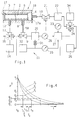
- Figure 1 shows a schematic representation of a device according to the invention for measuring the tensile resistance of filter rods or other rod-shaped articles of the tobacco processing industry. Essential components of the arrangement are shown as blocks. The pneumatic connections are drawn with thick lines, the electrical connections with thin lines. This also applies to the representation in the other figures.
- a measuring head 1 for testing the tensile resistance of a filter rod 2 is shown in section.
- the measuring head 1 has a measuring head housing 3 with an essentially circular cylindrical chamber 4.
- a hose-like sleeve 6 is inserted into the measuring chamber 4, the axial length of which is approximately equal to the length of the filter rods 2 to be tested.
- the diameter of the sleeve 6 is somewhat smaller than the diameter of the article to be tested, so that it lies tightly around the outer envelope of the article to be tested without gaps or wrinkles.
- the sleeve 6 is firmly and tightly connected at its two ends to the inner wall of the measuring chamber 4, so that a gas space 7 is formed between the inner wall of the measuring chamber 4 and the sleeve 6.
- This gas space 7 is connected via a first connection 8 and a valve 9 to a gas supply device 11 and via a second connection 12 and a valve 13 to a vacuum device 14.
- the vacuum device 14 serves to widen the sleeve 6 by sucking air out of the gas space 7, so that a filter rod can be inserted or removed.
- the gas space 7 is vented via a connection 16, so that the sleeve 6 relaxes tightly and tightly around the filter rod 2 introduced into the measuring chamber 4.
- One end 17 of the measuring chamber 4 is open to the atmosphere.
- the other measuring chamber end 17a is closed airtight by a cover 18.
- An air connection line 19 leads through the measuring chamber cover 18 and connects the measuring chamber end 17a via a first valve 21 to a pressure vessel 22 with a pressure sensor 23, which in turn is connected via a second valve 24 to a vacuum source.
- the suction side of a pump 26 can be provided as the vacuum source.
- the pressure sensor 23 of the pressure vessel 22 is connected to an evaluation and control arrangement 27, which is connected on the output side to actuators of the valves 21 and 24.
- the actuators of the valves 9 and 13 are also connected to the evaluation and control arrangement 27.
- the gas or air supply device 11 has a pre-pressure container 29 provided with a pressure sensor 28.
- This admission pressure container 29 is connected via a throttle 31 to an overpressure source 32, which can be the pressure side of the pump 26.
- the pressure of the pressure source 32 is detected upstream of the throttle 31 with a pressure sensor 33, which, like the pressure sensor 28, is connected to the evaluation and control arrangement 27, and is constantly regulated.
- the sleeve 6 is first widened by applying a negative pressure to the gas space 7, so that the filter rod 2 can be inserted comfortably.
- the valve 9 is closed, while the valve 13 opens the connection to the vacuum source 14.
- the suction side of the pump 26, which is connected via corresponding lines and valves, can again serve as the vacuum source 14, which is not shown here.
- stop means are provided, which are also shown in the drawing are not shown.
- a sensing element not shown, is provided, which determines the presence of a filter rod in the correct position.
- the gas space 7 is released via the connection 16, so that the sleeve 6 relaxes and lies tightly around the outer casing of the filter rod 2.
- a vacuum is built up in the pressure vessel 22 from the vacuum source 26 via the open valve 24. If a predetermined vacuum is reached, this is applied to the measuring chamber 4 by closing the valve 24 and opening the valve 21 as the initial pressure P0 (see FIG. 4). As a result, air is drawn from the open end 17 of the measuring chamber through the filter rod into the pressure vessel 22, the negative pressure of which is thereby reduced.
- the pressure P in the pressure volume 22 is plotted against the time t from the opening of the valve 21 at the time t0.
- the pressure curve in the pressure volume 22 is detected by several pressure measurements in succession with the pressure sensor 23 and analyzed by the evaluation and control system.
- the time course of the pressure change in the pressure vessel 22 is determined from the chronological sequence of the pressure measurements of the pressure sensor 23 and from the size of the respective pressure measurement values.
- the evaluation and control arrangement 27 calculates the tensile resistance of the filter rod 2 in the measuring chamber 4 from this time course of the pressure change.
- the procedure is as follows. As soon as a first filter rod is positioned in the measuring chamber 4, as described above, and the predetermined negative pressure (initial pressure P0) is built up in the pressure volume 22, the valve 24 closed and the valve 21 opened. An air flow now flows through the filter rod 2, which depends solely on the tensile resistance of the filter rod and causes a characteristic exponential decrease in the vacuum. The time course of the decrease in vacuum is shown as curve F1 in FIG. 4. It results from the initial pressure P0 and from a residual pressure P E1 existing in the pressure volume at the predetermined time t E.
- the pulling resistance of the first filter rod is calculated from the time constant of the curve shape F1 with the aid of the evaluation and control arrangement 27 and made available as a corresponding test signal.
- the same procedure is followed with the following filter rods.
- the tensile resistance of the second filter rod is expressed in the curve F2, which has the residual pressure P E2 at time t E.
- the curve F2 of the decrease in vacuum via the second filter rod shows that this tensile resistance differs from that of the first and also from that of the third, which is represented by the curve F3 and the residual pressure P E3 at time t E.
- the tensile resistance of the filter rods can be determined in a simple manner by ascertaining the pressure curve in the pressure volume 22 in a predetermined fixed period of time, which in the present example begins at t dem, the time at which the valve 21 opens, and ends at t E .
- t0 does not have to coincide with the opening of the valve 21
- the measuring time t0 - t E can also begin after the opening of the valve 21, whereby the pressure prevailing at the time in the pressure volume 22 must be taken into account as the initial pressure P0.
- the method according to the invention also includes the following variant, in which the time is measured, the pressure required to drop to predetermined constant pressure values P1, P2 and P3. For a first filter rod, this is based on the curve F1 explained in more detail in FIG. 4. In this case, three constant pressure values P1, P2 and P3 are given. If the negative pressure now drops after opening the valve 21 from the initial pressure P so, it reaches the first predetermined pressure value P1 at time t1, the second pressure value P2 at time t2 and the third pressure value P3 at time t3.
- the time T1 between t1 and t2 and the time T2 between t2 and t3 are measured. From these times and the specified pressure values, the exponential time course F1 of the pressure change results, from which the tensile resistance of the filter rod is determined.
- the evaluation and control arrangement 27 generates test signals which can be used for regulating the tensile resistance of the filter rod production. Filter rods with unacceptable tension resistance can be removed on the basis of the measurement. Acceptable filter rods are returned to the manufacturing process.
- the measuring head 2 shown is also excellently suitable for measuring the diameter of a filter rod 2 positioned in the measuring chamber 4.
- a constant overpressure is generated by means of the pressure source 32 and monitored with the pressure sensor 33, which is connected via the throttle 31 to the pre-pressure container 29 is created. If the valve 9 is now opened with the valve 13 open to the atmosphere, an air flow arises in the gas space 7, the size of which is directly dependent on the diameter of the clamped filter rod 2.
- This air flow is decisive for the pressure in the pre-pressure container 29, which is detected by the pressure sensor 28, which generates a corresponding measurement signal and outputs it to the evaluation and control arrangement.
- the evaluation and control arrangement processes this measurement signal to a diameter of Filter rod 2 representing the diameter signal.
- a two-way valve can be used as the valve 24, which connects the suction side of the pump 26 provided as a vacuum source on the one hand to the pressure vessel 22 and on the other hand either to the atmosphere or to a second measuring device 34 for the tension resistance measurement.
- the pressure vessel of the second measuring device 34 is brought to a negative pressure by the negative pressure source 26, while the tensile resistance test on the filter rod 2 takes place in the measuring head 1.
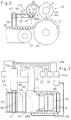
- FIGS. 2 and 3 show the arrangement of two test heads for measuring the tensile resistance in a machine for the production of filter rods, of which only the last conveyor drum 36 and an outfeed belt 38 guided around a deflection roller 37 are shown.
- a transfer means 39 is assigned to the last conveyor drum 36, which has a removal conveyor 42 rotating in the direction of the arrow 41 and parallel to the last conveyor drum 36 as well as an intermediate storage 43.
- an axially parallel receptacle 44 is provided, each of which receives an article 2 from the series of articles conveyed by the conveying drum 36.
- the removal conveyor 42 delivers the article 2 to a guide screen 45 of the clipboard 43, on which along the article in the direction of the arrow 46 it enters an insertion trough 47 which is axially aligned with the measuring chamber 4 of the measuring head 1.
- the filter rod is pushed longitudinally axially into the measuring chamber 4 of the measuring head by means of a blast of air from a blowing nozzle 48a connected to a pressure source 48 (see FIG. 3), while the sleeve 6 in the above in connection with FIG. 1 described way is expanded.
- the measuring head 1 is attached to a swivel arm 49 which the Measuring head 1 swings out of its push-in position shown in FIG. 2 into a measuring position and back.
- the swivel arm 49 carries a second measuring head 52, which is constructed in the same way as the first measuring head 1 and which alternately accommodates filter rods for measuring the tensile resistance.
- the second measuring head 52 belongs to the second measuring device 34 indicated in FIG. 1.
- the pivot arm 49 can be pivoted about an axis 53 parallel to the axes of the drum 36 and the removal conveyor 42.
- the tensile resistance measurement described above takes place in the measuring head 52.
- the tested filter rod is ejected from the measuring head 52 by means of a blast of air from a blowing nozzle 54a (FIG. 3) connected to a pressure source 54 and returned to the flow of the filter rods on the belt 38.
- guide plates 56 and a stop 57 are provided which form a chute leading to the filter rod and opening on the cantilever belt 38. This ensures that the tensile resistance measurement does not lead to unnecessary rejects.
- FIG. 3 again shows some of the various pressure sources which are connected to the movable test heads via flexible hose lines 19, 19a, 58, 59.
- the method according to the invention takes advantage of the knowledge that it is not necessary to measure the tensile resistance of each individual filter rod in order to obtain a reliable statement about the tensile resistance of all filter rods.
- Experience has shown that the draw resistance and the density of the filter rods change only very slowly during filter manufacture, so that sudden changes in draw resistance are not to be expected.
- Changes in tensile resistance can therefore also be detected if only about one percent of the filter rods are checked in a highly productive production machine. This means that there is enough time for each individual train resistance measurement to achieve very precise and reliable measurement results.
- the test signals obtained on the basis of this tensile resistance measurement can be used to display the tensile resistance and / or to regulate the manufacture of the filter rod to a constant tensile resistance.
- the pressure ratios can also be reversed in the tensile resistance and diameter measurement.
- an overpressure can be generated in the pressure vessel 22, which is reduced via the filter rod 2 for the measurement of the tensile resistance.
- the measurement process is the same as described above.
- a negative pressure can be produced in the pre-pressure container 29 for the diameter measurement without the measuring process being changed.
Landscapes
- Chemical & Material Sciences (AREA)
- Physics & Mathematics (AREA)
- Analytical Chemistry (AREA)
- Dispersion Chemistry (AREA)
- Health & Medical Sciences (AREA)
- Life Sciences & Earth Sciences (AREA)
- Fluid Mechanics (AREA)
- Biochemistry (AREA)
- General Health & Medical Sciences (AREA)
- General Physics & Mathematics (AREA)
- Immunology (AREA)
- Pathology (AREA)
- Investigating Strength Of Materials By Application Of Mechanical Stress (AREA)
- Measuring Fluid Pressure (AREA)
- Manufacturing Of Cigar And Cigarette Tobacco (AREA)
Applications Claiming Priority (2)
| Application Number | Priority Date | Filing Date | Title |
|---|---|---|---|
| DE4316723 | 1993-05-19 | ||
| DE19934316723 DE4316723A1 (de) | 1993-05-19 | 1993-05-19 | Verfahren und Vorrichtung zum Prüfen des Zugwiderstandes von Filterstäben |
Publications (1)
| Publication Number | Publication Date |
|---|---|
| EP0630585A1 true EP0630585A1 (fr) | 1994-12-28 |
Family
ID=6488445
Family Applications (1)
| Application Number | Title | Priority Date | Filing Date |
|---|---|---|---|
| EP94107087A Ceased EP0630585A1 (fr) | 1993-05-19 | 1994-05-06 | Procédé et dispositif de contrôle de la résistance à l'aspiration des tiges de filtres |
Country Status (3)
| Country | Link |
|---|---|
| EP (1) | EP0630585A1 (fr) |
| JP (1) | JPH0755690A (fr) |
| DE (1) | DE4316723A1 (fr) |
Cited By (10)
| Publication number | Priority date | Publication date | Assignee | Title |
|---|---|---|---|---|
| EP0815750A1 (fr) * | 1996-06-25 | 1998-01-07 | Hoechst Celanese Corporation | Dispositif pour tester la chute de pression des tiges de filtre |
| ES2157693A1 (es) * | 1996-03-08 | 2001-08-16 | Univ Catalunya Politecnica | Un aparato para la determinacion de aeropermeabilidad de medios filtrantes. |
| GB2397486A (en) * | 2003-01-24 | 2004-07-28 | Molins Plc | Sleeves for use in pressure drop devices and/or ventilation measuring devices |
| EP1519186A1 (fr) * | 2003-09-27 | 2005-03-30 | Bayerische Motoren Werke Aktiengesellschaft | Méthode et appareil de test pour des matériaux perméables à l'air |
| GB2423461A (en) * | 2005-02-25 | 2006-08-30 | Molins Plc | Device for occluding holes in smoking articles |
| CN102564892A (zh) * | 2011-12-09 | 2012-07-11 | 浙江中烟工业有限责任公司 | 吸阻标准棒压降减少值的测量方法以及该值用于检测吸阻仪抽吸管路设计是否合理的方法 |
| CN102708304A (zh) * | 2012-06-15 | 2012-10-03 | 川渝中烟工业有限责任公司 | 一种预测滤棒吸阻的方法 |
| CN104344926A (zh) * | 2013-07-29 | 2015-02-11 | Fnc科技株式会社 | 过滤器的水头损失水力学试验装置及方法 |
| CN118663586A (zh) * | 2024-07-09 | 2024-09-20 | 苏州濯英机电科技有限公司 | 一种烟用滤棒自动检测挑选装置 |
| CN119406764A (zh) * | 2024-12-06 | 2025-02-11 | 河北白沙烟草有限责任公司 | 滤棒检测剔除装置及方法 |
Families Citing this family (9)
| Publication number | Priority date | Publication date | Assignee | Title |
|---|---|---|---|---|
| DE102006041191C5 (de) * | 2006-08-30 | 2016-08-04 | Tews Elektronik Dipl.-Ing. Manfred Tews | Filtermeßstabstation sowie Verfahren zur Messung der Masse eines Weichmachers in einem Filterstab |
| DE202007001196U1 (de) | 2006-08-30 | 2007-05-31 | Tews Elektronik Dipl.-Ing. Manfred Tews | Filterstabmeßstation zur Messung der Masse eines Weichmachers, der Feuchtigkeit und/oder des trockenen Filtermaterials in einem Filterstab |
| RU2428083C1 (ru) * | 2009-12-28 | 2011-09-10 | Государственное научное учреждение Всероссийский научно-исследовательский институт табака, махорки и табачных изделий Российской академии сельскохозяйственных наук (ГНУ ВНИИТТИ Россельхозакадемии) | Способ оценки степени усилия для вдыхания табачного дыма и контроля качества сигарет |
| DE102010063593A1 (de) | 2010-12-20 | 2012-06-21 | Hauni Maschinenbau Ag | Faservliesherstellung |
| CN102590057B (zh) * | 2011-12-20 | 2014-06-04 | 浙江中烟工业有限责任公司 | 吸阻标准棒吸阻值的测量方法和用于验证吸阻标准棒校准值的方法 |
| DE102012102337A1 (de) * | 2012-03-20 | 2013-10-10 | Hauni Maschinenbau Ag | Messanordnung, ausgebildet und eingerichtet zum Messen von in Strangeinheiten der Tabak verarbeitenden Industrie hergestellten Strängen und/oder Strangabschnitten sowie Strangeinheit mit einer solchen Messanordnung und Verfahren zum Messen |
| CN102692205B (zh) * | 2012-06-15 | 2015-09-09 | 川渝中烟工业有限责任公司 | 一种评价丝束纵向表面积的方法及其应用 |
| CN109945943B (zh) * | 2019-04-19 | 2023-09-26 | 中国人民解放军海军工程大学 | 适用于不同流体设备的双向流阻测试系统及方法 |
| CN110411738B (zh) * | 2019-08-20 | 2021-07-06 | 合肥通用机械研究院有限公司 | 一种模块化阀门流量流阻测试系统及测试方法 |
Citations (7)
| Publication number | Priority date | Publication date | Assignee | Title |
|---|---|---|---|---|
| US3395570A (en) * | 1964-12-18 | 1968-08-06 | Hauni Werke Koerber And Co K G | Method and apparatus for testing cigarettes or the like |
| DE2813315A1 (de) * | 1978-03-28 | 1979-10-11 | Hauni Werke Koerber & Co Kg | Vorrichtung zum pruefen des zugwiderstandes von stabfoermigen artikeln der tabakverarbeitenden industrie |
| GB2018433A (en) * | 1978-03-22 | 1979-10-17 | Cir Spa Divisione Sasib | Method for testing cigarettes |
| GB2061527A (en) * | 1979-10-19 | 1981-05-13 | Imp Group Ltd | Testing Air-permeable Rod-like Articles |
| GB2068870A (en) * | 1980-01-24 | 1981-08-19 | Baumgartner Papiers Sa | Sampling apparatus for a production line |
| US4341109A (en) * | 1980-07-07 | 1982-07-27 | Eastman Kodak Company | Method and apparatus for determining cigarette filter rod pressure drop |
| FR2551632A1 (fr) * | 1983-09-12 | 1985-03-15 | Gd Spa | Procede pour prelever des echantillons de cigarettes sur une machine d'assemblage de filtres |
-
1993
- 1993-05-19 DE DE19934316723 patent/DE4316723A1/de not_active Withdrawn
-
1994
- 1994-05-06 EP EP94107087A patent/EP0630585A1/fr not_active Ceased
- 1994-05-17 JP JP10301094A patent/JPH0755690A/ja not_active Withdrawn
Patent Citations (7)
| Publication number | Priority date | Publication date | Assignee | Title |
|---|---|---|---|---|
| US3395570A (en) * | 1964-12-18 | 1968-08-06 | Hauni Werke Koerber And Co K G | Method and apparatus for testing cigarettes or the like |
| GB2018433A (en) * | 1978-03-22 | 1979-10-17 | Cir Spa Divisione Sasib | Method for testing cigarettes |
| DE2813315A1 (de) * | 1978-03-28 | 1979-10-11 | Hauni Werke Koerber & Co Kg | Vorrichtung zum pruefen des zugwiderstandes von stabfoermigen artikeln der tabakverarbeitenden industrie |
| GB2061527A (en) * | 1979-10-19 | 1981-05-13 | Imp Group Ltd | Testing Air-permeable Rod-like Articles |
| GB2068870A (en) * | 1980-01-24 | 1981-08-19 | Baumgartner Papiers Sa | Sampling apparatus for a production line |
| US4341109A (en) * | 1980-07-07 | 1982-07-27 | Eastman Kodak Company | Method and apparatus for determining cigarette filter rod pressure drop |
| FR2551632A1 (fr) * | 1983-09-12 | 1985-03-15 | Gd Spa | Procede pour prelever des echantillons de cigarettes sur une machine d'assemblage de filtres |
Cited By (13)
| Publication number | Priority date | Publication date | Assignee | Title |
|---|---|---|---|---|
| ES2157693A1 (es) * | 1996-03-08 | 2001-08-16 | Univ Catalunya Politecnica | Un aparato para la determinacion de aeropermeabilidad de medios filtrantes. |
| EP0815750A1 (fr) * | 1996-06-25 | 1998-01-07 | Hoechst Celanese Corporation | Dispositif pour tester la chute de pression des tiges de filtre |
| GB2397486A (en) * | 2003-01-24 | 2004-07-28 | Molins Plc | Sleeves for use in pressure drop devices and/or ventilation measuring devices |
| GB2397486B (en) * | 2003-01-24 | 2005-07-13 | Molins Plc | Improved measuring device |
| EP1519186A1 (fr) * | 2003-09-27 | 2005-03-30 | Bayerische Motoren Werke Aktiengesellschaft | Méthode et appareil de test pour des matériaux perméables à l'air |
| GB2423461A (en) * | 2005-02-25 | 2006-08-30 | Molins Plc | Device for occluding holes in smoking articles |
| CN102564892A (zh) * | 2011-12-09 | 2012-07-11 | 浙江中烟工业有限责任公司 | 吸阻标准棒压降减少值的测量方法以及该值用于检测吸阻仪抽吸管路设计是否合理的方法 |
| CN102564892B (zh) * | 2011-12-09 | 2015-05-06 | 浙江中烟工业有限责任公司 | 吸阻标准棒压降减少值的测量方法以及该值用于检测吸阻仪抽吸管路设计是否合理的方法 |
| CN102708304A (zh) * | 2012-06-15 | 2012-10-03 | 川渝中烟工业有限责任公司 | 一种预测滤棒吸阻的方法 |
| CN102708304B (zh) * | 2012-06-15 | 2015-07-22 | 川渝中烟工业有限责任公司 | 一种预测滤棒吸阻的方法 |
| CN104344926A (zh) * | 2013-07-29 | 2015-02-11 | Fnc科技株式会社 | 过滤器的水头损失水力学试验装置及方法 |
| CN118663586A (zh) * | 2024-07-09 | 2024-09-20 | 苏州濯英机电科技有限公司 | 一种烟用滤棒自动检测挑选装置 |
| CN119406764A (zh) * | 2024-12-06 | 2025-02-11 | 河北白沙烟草有限责任公司 | 滤棒检测剔除装置及方法 |
Also Published As
| Publication number | Publication date |
|---|---|
| DE4316723A1 (de) | 1994-11-24 |
| JPH0755690A (ja) | 1995-03-03 |
Similar Documents
| Publication | Publication Date | Title |
|---|---|---|
| EP0630585A1 (fr) | Procédé et dispositif de contrôle de la résistance à l'aspiration des tiges de filtres | |
| DE2434736C3 (de) | Verfahren und Anordnung zum Prüfen der Umhüllung stabf örmiger Artikel der tabakverarbeitenden Industrie | |
| DE1295443B (de) | Verfahren und Vorrichtung zum Feststellen von Fehlern in der Fuellung und der Umhuellung von Zigaretten oder anderen stabfoermigen Gegenstaenden | |
| DE2839927A1 (de) | Verfahren und vorrichtung zum messen der physikalischen eigenschaften von zigarettenfiltern | |
| DE2813315A1 (de) | Vorrichtung zum pruefen des zugwiderstandes von stabfoermigen artikeln der tabakverarbeitenden industrie | |
| CH661126A5 (de) | Verfahren und vorrichtung zum pruefen von stangenartigen gasdurchlaessigen gegenstaenden. | |
| DE2653733A1 (de) | Verfahren und anordnung zum pruefen einer zone gewuenschter luftdurchlaessigkeit in einer umhuellung stabfoermiger rauchartikel | |
| DE2348825A1 (de) | Verfahren und vorrichtung zum erzeugen eines gasdrucksignals | |
| DE1025173B (de) | Vorrichtung zum Bestimmen des Zugwiderstandes von Zigaretten | |
| DE2003691C3 (de) | Vorrichtung zum Prüfen des Füllgrades von Zigaretten | |
| DE3017023A1 (de) | Pruefvorrichtung fuer filterzigaretten | |
| DE19805236C2 (de) | Verfahren und Vorrichtung zur Ermittlung des Volumens eines keramischen Probenkörpers | |
| DE2760354C2 (fr) | ||
| DE69410670T2 (de) | norrichtung zur Porositätsmessung eines Filterelementes | |
| DE2403072A1 (de) | Verfahren und vorrichtung zum pruefen des zugwiderstandes von zigaretten oder dergleichen stabfoermigen artikeln | |
| DE1532255C3 (de) | Vorrichtung zur Prüfung von Zigaretten auf Nebenluft bzw. Undichtigkeit | |
| DE2444708C2 (fr) | ||
| EP1495684B1 (fr) | Eclusage de tiges de filtre au dehors d'une conduite de transport | |
| WO1988009492A1 (fr) | Procede et dispositif de determination de la teneur en suie de gaz de fumee | |
| DE2550536B2 (de) | Zigarettenprüfvorrichtung | |
| DE2648773B2 (de) | Verfahren und Vorrichtung zum Prüfen von fertiggestellten Zigaretten oder ähnlichen Produkten | |
| EP0852711B1 (fr) | Dispositif permettant de determiner des profils de concentration de substances liquides ou gazeuses le long d'une section | |
| DE2103603A1 (de) | Prüfgerät fur Zigaretten und Filter | |
| DE2109412C3 (de) | Zigarettenpriifeinrichtung | |
| DE3786074T2 (de) | Apparat zum Prüfen von Behälter. |
Legal Events
| Date | Code | Title | Description |
|---|---|---|---|
| PUAI | Public reference made under article 153(3) epc to a published international application that has entered the european phase |
Free format text: ORIGINAL CODE: 0009012 |
|
| AK | Designated contracting states |
Kind code of ref document: A1 Designated state(s): AT BE CH DE ES FR GB IT LI NL SE |
|
| 17P | Request for examination filed |
Effective date: 19950603 |
|
| RAP1 | Party data changed (applicant data changed or rights of an application transferred) |
Owner name: HAUNI MASCHINENBAU AKTIENGESELLSCHAFT |
|
| 17Q | First examination report despatched |
Effective date: 19961206 |
|
| GRAG | Despatch of communication of intention to grant |
Free format text: ORIGINAL CODE: EPIDOS AGRA |
|
| STAA | Information on the status of an ep patent application or granted ep patent |
Free format text: STATUS: THE APPLICATION HAS BEEN REFUSED |
|
| 18R | Application refused |
Effective date: 19980528 |