EP0630700B1 - Oberes Werkzeug für Biegepresse - Google Patents
Oberes Werkzeug für Biegepresse Download PDFInfo
- Publication number
- EP0630700B1 EP0630700B1 EP19940107730 EP94107730A EP0630700B1 EP 0630700 B1 EP0630700 B1 EP 0630700B1 EP 19940107730 EP19940107730 EP 19940107730 EP 94107730 A EP94107730 A EP 94107730A EP 0630700 B1 EP0630700 B1 EP 0630700B1
- Authority
- EP
- European Patent Office
- Prior art keywords
- upper tool
- wedge
- support plate
- engage
- actuated member
- Prior art date
- Legal status (The legal status is an assumption and is not a legal conclusion. Google has not performed a legal analysis and makes no representation as to the accuracy of the status listed.)
- Expired - Lifetime
Links
- 230000002265 prevention Effects 0.000 claims description 3
- 238000010276 construction Methods 0.000 description 9
- 238000005452 bending Methods 0.000 description 2
- 230000000694 effects Effects 0.000 description 2
- 239000012530 fluid Substances 0.000 description 2
- 239000002184 metal Substances 0.000 description 2
- 238000006243 chemical reaction Methods 0.000 description 1
- 230000006835 compression Effects 0.000 description 1
- 238000007906 compression Methods 0.000 description 1
- 238000006073 displacement reaction Methods 0.000 description 1
- 230000005489 elastic deformation Effects 0.000 description 1
- 238000004519 manufacturing process Methods 0.000 description 1
- 238000000034 method Methods 0.000 description 1
- 230000000717 retained effect Effects 0.000 description 1
Images


Classifications
-
- B—PERFORMING OPERATIONS; TRANSPORTING
- B21—MECHANICAL METAL-WORKING WITHOUT ESSENTIALLY REMOVING MATERIAL; PUNCHING METAL
- B21D—WORKING OR PROCESSING OF SHEET METAL OR METAL TUBES, RODS OR PROFILES WITHOUT ESSENTIALLY REMOVING MATERIAL; PUNCHING METAL
- B21D5/00—Bending sheet metal along straight lines, e.g. to form simple curves
- B21D5/02—Bending sheet metal along straight lines, e.g. to form simple curves on press brakes without making use of clamping means
- B21D5/0209—Tools therefor
- B21D5/0236—Tool clamping
-
- B—PERFORMING OPERATIONS; TRANSPORTING
- B21—MECHANICAL METAL-WORKING WITHOUT ESSENTIALLY REMOVING MATERIAL; PUNCHING METAL
- B21D—WORKING OR PROCESSING OF SHEET METAL OR METAL TUBES, RODS OR PROFILES WITHOUT ESSENTIALLY REMOVING MATERIAL; PUNCHING METAL
- B21D5/00—Bending sheet metal along straight lines, e.g. to form simple curves
- B21D5/02—Bending sheet metal along straight lines, e.g. to form simple curves on press brakes without making use of clamping means
- B21D5/0209—Tools therefor
Definitions
- the present invention relates to an upper tool in combination with an upper tool holder for a press brake according to the preamble of claim 1.
- the structure of a press brake is such that an upper table (referred to as an upper apron, sometimes) and a lower table (referred to as a lower apron, sometimes) are provided so as to be opposed vertically to each other and further any one of the upper and lower tables is moved up and down relative to the other as a ram.
- an upper table referred to as an upper apron, sometimes
- a lower table referred to as a lower apron, sometimes
- an upper tool is attached to the lower portion of the upper table and a lower tool is attached to the upper portion of the lower table.
- work disposed between the upper and lower tools can be bent when both the tools are engaged with each other by moving the movable-side table up and down.
- a number of upper tool holder devices are attached to the lower portion of the upper table, and further a number of tools are removably supported by a number of the upper tool holder devices, respectively.
- an upper tool clamp is mounted on a holder body attached to the lower portion of the upper table, and the upper portion of the upper tool is strongly fastened and fixed between the holder body and the upper tool clamp when the upper clamp is fastened with fastening bolts.
- the present invention provides an upper tool in combination with an upper tool holder for a press brake according to claim 1.
- the push actuating means is a lower surface of an engage groove portion extending horizontally and formed in any of a front or rear surface of the upper tool.
- the push actuating means is a lower surface of an engage groove portion extending horizontally and formed in any of front and rear surfaces of the upper tool, an upper surface of the engage groove portion being engageable with a part of the actuated member.
- the push actuating means is a lower surface of an engage groove portion extending horizontally and formed in any of front and rear surfaces of the upper tool, the engage groove portion being formed between a vertical position roughly the same as a holder contact surface formed at a shoulder portion of the upper tool and another vertical position slightly lower than an upper end of the upper tool.
- the push actuating means is a lower surface of an engage groove portion rectangular in cross section and formed in any of front and rear surfaces of the upper tool, the upper surface of said engage groove portion being engageable with a projecting portion rectangular in cross section of the actuated member, and a vertical dimension of the rectangular projecting portion of the actuated member being determined to be slightly larger than that of the engage groove portion.
- the upper tool can be mounted to the upper tool holder device easily and securely without use of any tool.
- the upper tool is removably attached between an support plate provided at a lower portion of a holder body of an upper tool holder device mounted on an upper table of the press brake and an upper tool clamp pivotally attached to the upper holder body so as to push the upper tool against the support plate, wherein the upper tool is formed with: a contact surface brought into tight contact with a lower surface of the support plate; a slide surface brought into slidable contact with any of front and rear surfaces of the support plate; a wedge pushing-up portion for pushing upward a wedge-shaped member provided movably up and down at a lower portion of the upper tool clamp, in order to increase an upper tool clamping force by the upper tool clamp when the upper tool is moved upward relative to the support plate so that the contact surface of the upper tool can be brought into tight contact with the lower surface of the support plate; and a processing portion for processing work in cooperation with a lower tool.
- the wedge pushing-up portion is a lower surface formed in an engage groove portion formed in the upper tool so as to be engageable with and disengageable from an engage projecting portion of the wedge-shaped member.
- the engage groove portion is formed with an upper engage surface engageable with an upper surface of the engage projecting portion of the wedge-shaped member for prevention of the upper tool from being dropped from the upper tool holder device.
- the wedge pushing-up portion is an upper surface formed in an engage projecting portion formed in the upper tool so as to be engageable with and disengageable from an engage groove portion formed in the wedge-shaped member.
- the upper tool is removably attached between an support plate provided at a lower portion of a holder body of an upper tool holder device mounted on an upper table of the press brake and an upper tool clamp pivotally attached to the upper holder body so as to push the upper tool against the support plate
- the upper tool is formed with: a contact surface brought into tight contact with a lower surface of the support plate; a slide surface brought into slidable contact with any of front and rear surfaces of the support plate; a wedge pushing-up portion for pushing upward a wedge-shaped member provided movably up and down at a lower portion of the upper tool clamp in order to increase an upper tool clamping force by the upper tool clamp when the upper tool is moved upward relative to the support plate so that the contact surface of the upper tool can be brought into tight contact with the lower surface of the support plate; and a processing portion for processing work in cooperation with a lower tool, and wherein under the condition that the wedge pushing-up portion is brought into loose contact with the wedge-shaped member to push the wedge-shaped member upward,
- A denotes a dimension between a pivotal center of the upper tool clamp and an elastic member for pushing the upper tool clamp
- B denotes an average dimension between the same pivotal center and a push actuating portion at which the upper tool clamp pushes the upper tool against the support plate via the wedge-shaped member
- P denotes a pushing force for pushing the upper tool against the support plate
- K denotes the elastic modulus of the elastic member
- ⁇ denotes an inclination angle of the wedge-shaped member.
- the upper portion of the upper tool is pinched between the support plate of the upper tool holder device and the pivotal upper tool clamp; the engage groove portion formed in the upper tool is engaged with the engage projecting portion of the wedge-shaped member provided movably up and down at the lower portion of the upper tool clamp; and the upper tool is moved upward relative to the support plate to move upward the wedge-shaped member by the wedge pushing-up portion formed at the lower surface of the engage groove portion of the upper tool.
- the clamping force increases gradually by an elastic force of the elastic member, with the result that it is possible to clamp the upper tool securely.
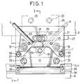
- the upper tool holder device 1 is removably attached to the lower portion of an upper table 3 of a press brake (not shown).
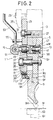
- the upper tool holder device 1 is provided with a holder body 5 removably attached to the upper table 3, an upper tool clamp 11 pivotally attached to the holder body 5 to push and fix an upper portion 9U of an upper tool 9 against and to a support plate 7 formed integrally with the lower portion of the holder body 5, a clamping force adjusting mechanism 13 for adjusting the clamping force to the upper tool clamp 11, a clamp releasing mechanism 15 for releasing the upper tool 9 clamped by the upper tool clamp 11, and a wedge-shaped member 17 (actuated member) movable up and down relative to the lower portion of the upper clamp 11 and formed with an engage projecting portion 17K engageable with an engage groove portion 9K (push actuating means) formed in the upper tool 9.
- the holder body 5 is formed with an upper block portion 5B having a thick wall extending in the front and rear direction (the right and left direction in Fig. 2) and a support plate 7 having a thin wall extending in the same direction and formed integral with the upper block portion 5B. Further, a mounting plate 21 is attached onto the front surface (on the left side surface in Fig. 2) of the upper block 5B of the holder body 5 with a plurality (two) of bolts 19 (see Fig. 1) so as to project upward away from the upper end portion of the holder body 5.
- a wedge member 27 extending horizontally is interposed between the upper surface of the holder body 5 and the lower surface of the upper table 3.
- a fixing bolt 31 is passed through a slot 29 formed in the mounting plate 21 so as to extend in the horizontal direction, and screwed into the wedge member 27 (see Fig. 2).
- the above-mentioned upper tool clamp 11 is a plate member having a width (in the right and left direction in Fig. 1) roughly the same as that of the holder body 5, and pivotally attached to the holder body 5 so as to fasten and fix the upper portion 9U of the upper tool 9 between the upper tool clamp 11 and the support plate 7 (as shown in Fig. 2) and to the support plate 7.
- the upper clamp 11 is supported so as to be pivotal in the front and rear direction by a plurality of mounting bolts 33 passing through a plurality (two) of through holes 11H formed at roughly the vertically middle portion of the upper tool clamp 11 and fixedly fastened toward the support plate 7 in the horizontal direction.
- a spherical washer 35 is interposed between each head of the mounting bolts 33 and the upper tool clamp 11, as shown in Fig.2.
- two coil springs 37 are elastically interposed between the upper tool clamp 11 and the support plate 7 so as to be urged away from each other.
- the upper tool clamp 11 is formed with an inclined surface 11S at the lower portion thereof, whose upper end portion is inclined toward the support plate 7.
- the wedge-shaped member (actuated member) 17 is disposed so as to be movable up and down relative to the inclined surface 11S.
- the upper tool clamp 11 is formed with two slots 11LH extending in the vertical direction on the left and right sides at the lower end portion thereof. Further, two mounting bolts 39 passing through these slots 11LH, respectively are screwed into the wedge-shaped member (actuated member) 17, so that the wedge-shaped member 17 can be attached to the upper tool clamp 11 so as to be movable up and down, because the two mounting bolts 29 are movable within the slots 11LH. Further, the wedge-shaped member 17 is formed with the engage projecting portion 17K at an appropriate position thereof so as to be removably engageable with a horizontal engage groove portion 9K formed in the upper tool 9.
- the engage projecting portion 17K is a projecting portion projecting outward from the wedge-shaped member (actuated member) 17, the cross-sectional shape of the engage projecting portion 17K is rectangular in shape, as shown in Fig. 2.
- clamping force adjusting mechanism 13 is provided in a horizontal hole 5H formed in the upper block portion 5B of the holder body 5, so as to apply an adjustable clamping force to the upper tool 9 clamped between the upper clamp 11 and the support plate 7.
- the clamping force adjusting mechanism 13 is composed of an adjust screw 41, a ring member 43 loosely fitted to the adjust screw 41, a nut member 45 in mesh with the adjust screw 41 to adjust the position of the ring member 43, and an elastic member 47 such as a spring disposed between a head portion 41H of the adjust screw 41 and the ring member 43.
- the head portion 41H of the adjust screw 41 is in contact with the inner bottom wall portion of the hole 5H, and further a cylindrical push member 49 (into which the nut member 45 is inserted) is in contact with the ring member 43. Further, the end portion of the fastening screw 51 of the clamping force releasing mechanism 15 provided on the upper tool clamp 11 is in contact with the push member 49.
- the clamp releasing mechanism 15 is composed of the fastening screw 51 passing through and screwed into the upper portion of the upper tool clamp 11 and a lever 53 formed integral with the fastening screw 51.
- a plurality of small restriction pieces (or members) 57 are attached to the holder body 5 with bolts 59 so as to be in contact with the upper surface of the upper tool clamp 11. Accordingly, the upper clamp 11 can fasten or fix the upper tool 9 at any predetermined position stably without being moved up and down.
- the upper tool 9 removably attached to the upper tool holder device 1 constructed as described above is formed with a contact surface 9F brought into contact with a lower end surface 7E of the support plate 7. Further, the upper tool 9 is formed with the upper portion 9U projecting upward from the contact surface 9F and with a slide surface 9S brought into slidable contact with the front surface of the support plate 7. Further, the upper tool 9 is formed with an engage groove portion (push actuating means) 9K on the surface opposite to the slide surface 9S. Further, the upper tool 9 is formed with a work processing portion 9M at the lower end portion thereof to bend a work K in cooperation with a lower tool 63 attached to the lower table 61 of the press brake.
- the engage groove of the engage groove portion 9K is formed into a rectangular shape in cross section in such a way that the upper surface of the engage groove portion (push actuating means) 9K serves as an engage surface engageable with the upper surface of the engage projecting portion 17K of the wedge-shaped member (actuated member) 17, and further the lower surface thereof parallel to the upper surface thereof serves as a push actuating means or a wedge pushing-up portion for pushing up the lower surface of the engage projecting portion 17K of the wedge-shaped member 17. Accordingly, the engage projecting portion 17K of the wedge-shaped member 17 can be engaged with the engage groove portion 9K of the upper tool 9. Further, the vertical dimension of the engage groove portion 9K is determined to be slightly larger than that of the engage projecting portion 17K so that the wedge-shaped member 17 is not moved up and down excessively relative to the upper tool 9.
- the upper tool 9 in the case where the upper tool 9 has been removed from the upper tool holder device 1, the upper tool 9 can be attached again to the upper tool holder device 1 as follows:
- the lever 53 of the clamp releasing mechanism 15 is pivoted clockwise in Fig. 1 to the rightward position (R) to fasten the fastening screw 51.
- R rightward position
- the movable side of the upper and lower tables 3 and 61 of the press brake is moved up and down to engage the upper and lower tools 9 and 63 correctly with each other.
- the upper tool 9 is generally moved upward relative to the holder body 5.
- the upper tool clamp 11 can clamp the upper portion 9U of the upper tool 9 more strongly and tightly due to the increased elastic force of the elastic member 47 of the clamping force adjusting mechanism 13, with the result that it is possible to attach the upper tool 9 easily to the upper tool holder device 1.
- the upper tool 9 in the case where the upper tool 9 has been already attached to the upper tool holder device 1, the upper tool 9 can be removed from the upper tool holder device 1 as follows:
- the lever 53 of the clamp releasing mechanism 15 is pivoted to the leftward position (L) in Fig. 1 to unfasten the fastening screw 51, so that the upper tool 9 is released from the fastening condition by the upper tool clamp 11.
- both the upper tool 9 and the wedge-shaped member 17 drop to the lowermost position due to their weights, respectively.
- an upper surface of the engage groove portion 9K of the upper tool 9 is engaged with the engage projecting portion 17K of the wedge-shaped member 17, it is possible to prevent the upper tool 9 from being further dropped, thus maintaining the safety.
- the upper tool and tool holder device 1 As understood already, in the upper tool and tool holder device 1 according to the present invention, it is possible to attach and remove the upper tool 9 to and from the upper tool holder device 1 easily, without use of any tool, in spite of the simple construction.
- the structure is such that when the lower surface of the engage groove portion 9K (push actuating means) of the upper tool 9 pushes upward the engage projecting portion 17K of the wedge-shaped member (actuated member) 17, the clamping force (push force) of the upper tool clamp 11 against the support plate 7 increases gradually with increasing upward movement of the wedge-shaped member 17. Therefore, the wedge-shaped member 17, the upper clamp 11 and the clamp force adjusting mechanism 13, etc. construct a sort of clamp force increasing mechanism for increasing the clamping force gradually when the wedge-shaped member 17 (which serves as an actuated member) is moved upward relative to the support plate 7.
- a clamping force adjusting mechanism 13 including the elastic member 47 As a part of the above-mentioned clamping force increasing mechanism, there is provided a clamping force adjusting mechanism 13 including the elastic member 47.
- a hydraulic cylinder filled with a compressive fluid e.g., gas
- the upper tool clamp 11 itself by a leaf spring without use of the clamping force adjusting mechanism 13.
- the elastic deformation of the upper tool clamp 11 itself is used to generate the clamping force.
- the clamping force increasing mechanism of the upper tool holder device can be constructed in various ways.
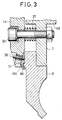
- Fig. 3 shows a second embodiment of the upper tool holder device 1, in which the wedge-shaped member (actuated member) 17 is formed with an engage groove portion 17K, and the upper tool 9 is formed with an engage projecting portion 9K (push actuating means) so as to be engageable with the engage groove portion 17K of the wedge-shaped member 17.
- the wedge-shaped member 17 Is pushed upward by the engage projecting portion 9K of the upper tool 9.
- Fig. 4 shows a third embodiment of the upper tool holder device 1, in which the wedge-shaped member (actuated member) 17 is additionally formed with an upper engage projecting portion 17P.
- the wedge-shaped member 17 is pushed upward by the upper surface of the upper tool 9.
- Figs. 5 to 7 show the fourth embodiment of the upper tool holder device 1 according to the present invention, in which both the surfaces of the upper tool 9 can be reversed relative to each other and further an additional upper tool 9 can be attached to the rear surface side of the support plate 7 in cooperation with another rear side upper tool clamp 65. Accordingly, the same reference numerals have been retained for the similar parts or elements which have the same functions as with the case of the first embodiment, and only the points different from the first embodiment will be described hereinbelow, without repeating the similar detailed description thereof.
- the rear side upper tool clamp 65 is provided on the rear side of the support plate 7.
- a stud 67 formed with a semi-spherical head 67H is provided horizontally by use of a mounting bolt 69 on the rear surface of the support plate 7 of the holder body 5.
- the rear side upper tool clamp 65 is pivotally supported by this stud 67.
- a tool hole 11T is formed in the front side upper tool clamp 11. Further, a rotation-stop pin 71 is attached to the head portion 67H of the stud 67 so as to be engaged with a groove 65G formed in the rear side upper tool clamp 65. Therefore, even when the mounting bolt 69 is rotated, the stud 67 will not be rotated.
- a small-diameter hole 73 is formed in the bottom wall portion of the hole 5H of the holder body 5. Further, a contact member 75 mounted on the upper portion of the rear side upper tool clamp 65 is passed through this small-diameter hole 73 and brought into contact with the head portion 41H of the adjusting screw 41.
- a ring nut 77 is screwed into the hole 5H on the left side (in Fig. 2) to restrict the movement of the push member 49 of the clamping force adjusting mechanism 13.
- the fourth embodiment it is possible to selectively attach the upper tool 9 reversed in the front and rear direction to the support plate 7 according to the bending shape of the work W. Further, the upper tool 9 can be attached to and removed from the upper tool holder device 1 easily for tool exchange.
- the upper tool holder device 1 and the upper tool 9 according to the present invention it is possible to attach and remove the upper tool 9 to and from the upper tool holder device 1 easily in spite of the simple construction, without dropping the upper tool 9 even when the upper tool 9 is released from the upper tool holder device 1, thus improving the safety of the upper tool exchange work.
- the upper tool 9 can be moved upward relative to the support plate 7 of the tool holder device 1, and the tool clamping force by the upper tool clamp 11 can be increased gradually when the wedge-shaped member (actuated member) 17 is pushed upward. Therefore, when the contact surface 9F of the upper tool 9 is brought into contact with the lower end surface 7E of the support plate 7, it is possible to obtain a sufficiently large clamping force.
- A denotes a dimension between the pivotal center of the upper tool clamp 11 and the elastic means 47 of the clamping force adjusting mechanism 13 for pushing the upper tool clamp 11;
- B denotes an average dimension between the same pivotal center and the push actuating portion at which the upper tool clamp 11 pushes the upper tool 9 against the support plate 7 via the wedge-shaped member 17;
- P denotes a pushing force for pushing the upper tool 9 against the support plate 7;
- K denotes the elastic modulus of the elastic means 47; and
- ⁇ denotes an inclination angle of the wedge-shaped member 17.
- Fig. 9 shows a fifth embodiment of the upper tool holder device 101 and the upper tool 9 according to the present invention.
- an upper tool holder device 101 is provided with a work cylinder 103. Further, the upper tool 9 is provided with a push actuating member (means) 107 for pushing upward an actuated rod (actuated member) 103P of the work cylinder 103.
- actuated member actuated member
- an upper clamp 111 is pivotally supported by a support plate 109 via a pin 113. This upper clamp 111 pushes and fixes the upper portion 9U of the upper tool 9 against and to the support plate 109 of the upper tool holder device 101.
- a piston rod 115P is provided at the upper portion of the upper tool clamp 111.
- the end of this piston rod 115P is reciprocatingly inserted into a clamp cylinder 115 attached to the support plate 109.
- the cylinder 115 is linked with the work cylinder 103 provided with the actuated rod 103P via a hydraulic circuit composed of a check valve CV, an open/close valve V, and an accumulator ACC.
- Fig. 10 shows a sixth embodiment of the present invention.
- the upper surface of the upper portion 9U of the upper tool 9 is used as a push actuating means. That is, when an actuated (rod) member 121 (movable up and down) is pushed upward by this push actuating means (the upper surface) of the upper tool 9, since an upper wedge member 125 is pushed upward via an elastic member 123 disposed on the upper portion of the actuated rod member 121, the upper clamping 111 is pivoted in the counterclockwise direction in Fig. 10, so that the upper tool 9 can be pushed against and fixed to the support plate 109.
- the upper tool and tool holder for a press brake comprises push actuating means (9K, 107, 9U) for actuating upward an actuated member (17, 103P, 121) movable up and down, in a clamping force increasing mechanism such that an upper tool clamping force can be increased gradually when the actuated member (17, 103P, 121) mounted on an upper holder device (1) of the press brake is moved upward. Therefore, it is possible to clamp the upper tool securely to the upper tool holder device without use of any tool.
- the upper tool is formed with only the push actuating means for pushing upward the actuated member. In other words, it is unnecessary to form the upper tool into a special shape.
- the push actuating means is a lower surface of an engage groove portion (9K) extending horizontally and formed in any of a front or rear surface of the upper tool (9). Therefore, the shape of the push actuating means is simple.
- the push actuating means is a lower surface of an engage groove portion (9K) extending horizontally and formed in any of front and rear surfaces of the upper tool (9), and an upper surface of the engage groove portion (9K) is engageable with a part of the actuated member (17). Therefore, the upper and lower surfaces of the engage groove portion formed in the upper tool can be utilized effectively.
- the push actuating means is a lower surface of an engage groove portion (9K) extending horizontally and formed in any of front and rear surfaces of the upper tool (9), and the engage groove portion (9K) is formed between a vertical position roughly the same as a holder contact surface (9F) formed at a shoulder portion of the upper tool (9) and another vertical position slightly lower than an upper end of the upper tool. Therefore, when the upper tool is clamped between the upper tool clamp and the support plate, no moment for pivoting the upper tool will not be generated, so that it is possible to fix and clamp the upper tool more securely.
- the upper tool and tool holder for a press brake comprises push actuating means (9K) for actuating upward an actuated member (17) movable up and down, in a clamping force increasing mechanism such that an upper tool clamping force can be increased gradually when the actuated member (17) mounted on an upper holder device (1) of the press brake is moved upward.
- the push actuating means (9K) is a lower surface of an engage groove portion (9K) rectangular in cross section and formed in any of front and rear surfaces of the upper tool (9); the upper surface of the engage groove portion (9K) is engageable with an engage projecting portion (17K) rectangular in cross section of the actuated member (17); and a vertical dimension of the rectangular engage projecting portion (17k) of the actuated member is determined to be slightly larger than that of the engage groove portion. Therefore, the upper tool can be removably attached to the upper tool holder device without applying an excessive vertical movement of the upper tool relative to the upper tool holder device, with the result that the upper tool can be exchanged stably.
- an upper tool for a press brake removably attached between an support plate (7) provided at a lower portion of a holder body (5) of an upper tool holder device (1) mounted on an upper table (3) of the press brake and an upper tool clamp (11) pivotally attached to the upper holder body (5) so as to push the upper tool (9) against the support plate (7)
- the upper tool is formed with: a contact surface (9F) brought into tight contact with a lower surface of the support plate (7); a slide surface (9S) brought into slidable contact with any of front and rear surfaces of the support plate; a wedge pushing-up portion (9K) for pushing upward a wedge-shaped member (17) provided movably up and down at a lower portion of the upper tool clamp (11), in order to increase an upper tool clamping force by the upper tool clamp (11) when the upper tool (9) is moved upward relative to the support plate (7) so that the contact surface (9F) of the upper tool can be brought into tight contact with the lower surface of the support plate; and a processing portion (9
- the wedge pushing-up portion (9K) is a lower surface formed in an engage groove portion (9K) formed in the upper tool so as to be engageable with and disengageable from an engage projecting portion (17K) of the wedge-shaped member (17). Further, the engage groove portion (9K) is formed with an upper engage surface engageable with an upper surface of the engage projecting portion (17K) of the wedge-shaped member (17) for prevention of the upper tool from being dropped from the upper tool holder device (1). Further, the wedge pushing-up portion (9K) is an upper surface formed in an engage projecting portion (9K) formed in the upper tool so as to be engageable with and disengageable from an engage groove portion (17K) formed in the wedge-shaped member (17).
- the upper tool and tool holder for a press brake it is possible to facilitate mounting and dismounting of the upper tool to and from the upper tool holder device, in the mechanism by which the upper tool clamping force can be increased gradually when the upper tool is moved upward relative to the support plate of the upper tool holder device. Further, since a sufficient clamping force can be obtained whenever the upper tool is mounted to the upper tool holder device, it is possible to prevent the upper tool from being dropped from the upper tool holder device due to insufficient clamping force, while preventing that the upper tool is difficult to be dismounted from the upper tool holder device due to an excessive tool clamping force. Furthermore, since the upper tool is kept held by the upper tool holder device whenever the upper tool is being replaced, it is possible to improve the safety of upper tool exchange work.
Landscapes
- Engineering & Computer Science (AREA)
- Mechanical Engineering (AREA)
- Bending Of Plates, Rods, And Pipes (AREA)
- Mounting, Exchange, And Manufacturing Of Dies (AREA)
Claims (13)
- Oberwerkzeug (9) in Verbindung mit einem Oberwerkzeughalter (1) für eine Presse, wobei das Oberwerkzeug (9) in Eingriff mit diesem Werkzeughalter (1) bringbar ist, dadurch gekennzeichnet, daß dieser Werkzeughalter (1) ein keilförmiges, betätigtes Element (17) beinhaltet, das auf und ab bewegbar ist,
wobei das Oberwerkzeug (9) eine Druckbetätigungseinrichtung (9K) aufweist zum Eingriff mit diesem betätigten Element (17) zum Bewirken einer nach aufwärts gerichteten Bewegung des betätigten Elementes (17), und zum Verhindern eines Herabfallens des Oberwerkzeuges (9) von dem Werkzeughalter (1), selbst wenn das Oberwerkzeug (9) von einem Klemmzustand gelöst ist, und wobei die Druckbetätigungseinrichtung (9K) mit diesem betätigten Element (17) zusammenwirkt, derart, daß eine Oberwerkzeug-Klemmkraft allmählich zunimmt, wenn das betätigte Element (17) nach oben bewegt wird. - Oberwerkzeug in Verbindung mit einem Oberwerkzeughalter für eine Presse nach Anspruch 1, wobei diese Druckbetätigungseinrichtung (9K) eine untere Oberfläche eines Eingriffsnutabschnittes ist, der sich horizontal erstreckt und in der vorderen oder hinteren Oberfläche des Oberwerkzeuges (9) ausgebildet ist.
- Oberwerkzeug in Verbindung mit einem Oberwerkzeughalter für eine Presse nach Anspruch 1 oder 2, wobei eine obere Oberfläche des Eingriffsnutabschnittes mit einem Teil des betätigten Elementes (17) in Eingriff bringbar ist.
- Oberwerkzeug in Verbindung mit einem Oberwerkzeughalter für eine Presse nach Anspruch 2 oder 3, wobei der Eingriffsnutabschnitt zwischen einer vertikalen Position, die ungefähr die gleiche ist wie die Position einer Halter-Kontaktoberfläche (9E), ausgebildet an einem Schulterabschnitt des Oberwerkzeuges (9), und einer anderen vertikalen Position geringfügig unterhalb eines oberen Endes des Oberwerkzeuges (9) ausgebildet ist.
- Oberwerkzeug in Verbindung mit einem Oberwerkzeughalter für eine Presse nach einem der Ansprüche 1 bis 4, wobei dieser Eingriffsabschnitt im Querschnitt rechteckig ist, die obere Oberfläche des Eingriffsnutabschnittes in Eingriff bringbar ist mit einem vorspringenden Abschnitt (17K) des betätigten Elementes (17), der im Querschnitt rechteckig ist, und eine vertikale Abmessung des rechteckigen, vorspringenden Abschnitts (17K) des betätigten Elementes (17) so festgelegt ist, daß sie geringfügig größer ist als diejenige des Eingriffsnutabschnittes.
- Oberwerkzeug in Verbindung mit einem Oberwerkzeughalter für eine Presse nach Anspruch 1, wobei dieser Oberwerkzeughalter (1) aufweist eine Tragplatte (7), die an einem unteren Abschnitt eines Haltekörpers (5) vorgesehen ist, um auf einem unteren Tisch (3) der Presse befestigt zu sein, und eine Oberwerkzeug-Klemmeinrichtung (11), die schwenkbar an dem oberen Haltekörper (5) angebracht ist, um das Oberwerkzeug (9) gegen die Tragplatte (7) zu drücken, wobei das Oberwerkzeug (9) aufweist:eine Kontaktoberfläche (9F), um in engen Kontakt mit einer unteren Oberfläche (7E) der Tragplatte (7) gebracht zu werden;eine Gleitoberfläche (9S), um in Gleitkontakt mit der vorderen oder hinteren Oberfläche der Tragplatte (7) gebracht zu werden;einen Keil-Aufwärtsdruckabschnitt, der diese Druckbetätigungseinrichtung bildet zum Aufwärtsdrücken dieses keilförmigen, betätigten Elementes (17), das aufwärts und abwärts bewegbar an einem unteren Abschnitt der Oberwerkzeug-Klemmeinrichtung (11) vorgesehen ist, um eine Oberwerkzeug-Klemmkraft durch die Oberwerkzeug-Klemmeinrichtung (11) zu erhöhen, wenn das Oberwerkzeug (9) nach oben relativ zu der Tragplatte (7) bewegt wird, so daß die Kontaktoberfläche (9F) des Oberwerkzeuges (9) in engen Kontakt mit der unteren Oberfläche (7E) der Tragplatte (7) gebracht werden kann; undeinen Bearbeitungsabschnitt (9M) zum Bearbeiten eines Werkstückes im Zusammenwirken mit dem Unterwerkzeug.
- Oberwerkzeug in Verbindung mit einem Oberwerkzeughalter für eine Presse nach Anspruch 6, wobei dieser Keil-Aufwärtsdruckabschnitt eine untere Oberfläche ist, die an einem Eingriffsnutabschnitt ausgebildet ist, vorgesehen in dem Oberwerkzeug (9), um in Eingriff mit und außer Eingriff von einem Eingriffsvorsprungabschnitt des keilförmigen, betätigten Elementes (17) zu gelangen.
- Oberwerkzeug in Verbindung mit einem Oberwerkzeughalter für eine Presse nach Anspruch 7, wobei der Eingriffsnutabschnitt mit einer oberen Eingriffsoberfläche ausgebildet ist, die in Eingriff mit einer oberen Oberfläche des Eingriffsvorsprungabschnittes des keilförmigen, betätigten Elements (17) bringbar ist, um ein Herunterfallen des Oberwerkzeuges von dem Oberwerkzeughalter (1) zu verhindern.
- Oberwerkzeug in Verbindung mit einem Oberwerkzeughalter für eine Presse nach Anspruch 6, wobei dieser Keil-Aufwärtsdruckabschnitt eine obere Oberfläche an einem Eingriffsvorsprungabschnitt ist, der an dem Oberwerkzeug (9) ausgebildet ist, um in Eingriff mit und außer Eingriff von einem Eingriffsnutabschnitt zu gelangen, der in dem keilförmigen, betätigten Element (17) ausgebildet ist.
- Oberwerkzeug in Verbindung mit einem Oberwerkzeughalter für eine Presse nach einem der Ansprüche 6 bis 9, wobei unter der Bedingung, daß der Keil-Aufwärtsdruckabschnitt in losen Kontakt mit dem keilförmigen Element gebracht ist, um das keilförmige Element nach oben zu drücken, ein Raum H zwischen der unteren Endoberfläche der Tragplatte und der Kontaktoberfläche des Oberwerkzeuges gegeben ist durch die folgende Formel:A eine Abmessung zwischen einem Schwenkzentrum der Oberwerkzeug-Klemmeinrichtung (11) und einem elastischen Teil (47) zum Drücken der Oberwerkzeug-Klemmeinrichtung (11) bezeichnet;B eine Durchschnittsabmessung zwischen demselben Schwenkzentrum und einem Druckbetätigungsabschnitt bezeichnet, an dem die Oberwerkzeug-Klemmeinrichtung (11) das Oberwerkzeug (9) über das keilförmige, betätigte Element (17) gegen die Tragplatte (7) drückt;P eine Druckkraft zum Drücken des Oberwerkzeuges (9) gegen die Tragplatte (7) bezeichnet;K den Elastizitätsmodul des elastischen Teiles (47) bezeichnet; und den Neigungswinkel des keilförmigen, betätigten Elementes (17) bezeichnet.
- Oberwerkzeug in Verbindung mit einem Oberwerkzeughalter für eine Presse nach einem der Ansprüche 1, 6, 9 oder 10, wobei das keilförmige, betätigte Element (17) eine Stop-Nut zum Eingriff mit dem Oberwerkzeug (9) aufweist, wobei das keilförmige, betätigte Element (17) vertikal beweglich an einem unteren Abschnitt der Oberwerkzeug-Klemmeinrichtung (11) vorgesehen ist, die schwenkbar an dem Oberwerkzeughalter (1) angebracht ist, und wobei das Oberwerkzeug (9) aufweist:eine Kontaktoberfläche (9F), die in Kontakt mit einer unteren Oberfläche einer Tragplatte (7) bringbar ist, die an einem unteren Abschnitt eines Haltekörpers eines Oberwerkzeughalters (1) vorgesehen ist, der anbringbar mit einem Obertisch (3) einer Presse verbindbar ist;eine Gleitoberfläche (9F), die in gleitenden Kontakt mit einer vorderen oder hinteren Oberfläche der Tragplatte (7) bringbar ist;einen Eingriffsvorsprung, der in Eingriff mit und außer Eingriff von der Stop-Nut des keilförmigen, betätigten Elements (17) bringbar ist; undeinem Werkstück-Bearbeitungsabschnitt (9M) zur Bearbeitung eines Werkstückes in Verbindung mit einem Unterwerkzeug.
- Oberwerkzeug in Verbindung mit einem Oberwerkzeughalter für eine Presse nach Anspruch 11, wobei der Eingriffsvorsprung des Oberwerkzeuges (9) eine Druckoberfläche aufweist zum Drücken einer inneren Oberfläche der Stop-Nut des keilförmigen, betätigten Elementes (17), um das keilförmige, betätigte Element zu bewegen.
- Oberwerkzeug in Verbindung mit einem Oberwerkzeughalter für eine Presse nach Anspruch 11 oder 12, wobei dieser Eingriffsvorsprung des Oberwerkzeuges (9) eine, ein Herabfallen verhindernde Oberfläche aufweist, um in Kontakt mit einer inneren Oberfläche der Stop-Nut des keilförmigen, betätigten Elementes (17) zu kommen, um ein Lösen des Oberwerkzeuges (9) von dem keilförmigen, betätigten Element (17) zu verhindern.
Applications Claiming Priority (3)
| Application Number | Priority Date | Filing Date | Title |
|---|---|---|---|
| JP11566593 | 1993-05-18 | ||
| JP11566593 | 1993-05-18 | ||
| JP115665/93 | 1993-05-18 |
Publications (2)
| Publication Number | Publication Date |
|---|---|
| EP0630700A1 EP0630700A1 (de) | 1994-12-28 |
| EP0630700B1 true EP0630700B1 (de) | 1999-08-04 |
Family
ID=14668272
Family Applications (1)
| Application Number | Title | Priority Date | Filing Date |
|---|---|---|---|
| EP19940107730 Expired - Lifetime EP0630700B1 (de) | 1993-05-18 | 1994-05-18 | Oberes Werkzeug für Biegepresse |
Country Status (4)
| Country | Link |
|---|---|
| EP (1) | EP0630700B1 (de) |
| JP (1) | JP3004597U (de) |
| CA (1) | CA2123844A1 (de) |
| DE (1) | DE69419838T2 (de) |
Families Citing this family (4)
| Publication number | Priority date | Publication date | Assignee | Title |
|---|---|---|---|---|
| DE19546969A1 (de) * | 1995-12-15 | 1997-06-19 | Amada Gmbh | Schnellspannvorrichtung für zumindest ein Werkzeug einer Bearbeitungsmaschine |
| AU2003289026A1 (en) * | 2002-12-12 | 2004-06-30 | Aoki, Eisuke | Cope holder device for press brake |
| CN101417303B (zh) * | 2008-12-01 | 2010-11-10 | 米路加(深圳)科技发展有限公司 | 一种模具夹具 |
| CN117428110A (zh) * | 2022-07-14 | 2024-01-23 | 贵州振华群英电器有限公司(国营第八九一厂) | 一种压弯及整形的新型模具结构及使用方法 |
Family Cites Families (3)
| Publication number | Priority date | Publication date | Assignee | Title |
|---|---|---|---|---|
| NL8802402A (nl) * | 1988-09-29 | 1990-04-17 | Wila Maschf Bv | Kleminrichting, bijv. voor het bovengereedschap van een kantpers. |
| FR2643838B1 (fr) * | 1989-03-02 | 1991-05-31 | Treillet Jean | Dispositif de fixation rigide pour des pieces suspendues telles que poincons de presse-plieuse |
| EP0569880B1 (de) * | 1992-05-15 | 1998-01-14 | Amada Metrecs Company, Limited | Oberwerkzeugträger für eine Presse |
-
1994
- 1994-05-17 JP JP1994005336U patent/JP3004597U/ja not_active Expired - Lifetime
- 1994-05-18 EP EP19940107730 patent/EP0630700B1/de not_active Expired - Lifetime
- 1994-05-18 CA CA 2123844 patent/CA2123844A1/en not_active Abandoned
- 1994-05-18 DE DE1994619838 patent/DE69419838T2/de not_active Expired - Fee Related
Also Published As
| Publication number | Publication date |
|---|---|
| DE69419838T2 (de) | 1999-11-25 |
| CA2123844A1 (en) | 1994-11-19 |
| JP3004597U (ja) | 1994-11-22 |
| DE69419838D1 (de) | 1999-09-09 |
| EP0630700A1 (de) | 1994-12-28 |
Similar Documents
| Publication | Publication Date | Title |
|---|---|---|
| US5572902A (en) | Upper tool holder apparatus for press brake and upper tool attachable thereto | |
| US5513514A (en) | Upper tool and upper tool holding device for press brake | |
| EP0682995B1 (de) | Oberwerkzeug und Oberwerkzeugträger mit einem solchen Oberwerkzeug zur Verwendung mit einer Biegepresse und Verfahren zur Befestigung des Oberwerkzeuges | |
| US5619885A (en) | Upper tool holder apparatus for press brake and method of holding the upper tool | |
| US5782308A (en) | Quick clamping device for at least one tool of a machine tool | |
| US5507170A (en) | Upper tool for press brake | |
| US5511407A (en) | Upper tool for press brake | |
| US6003360A (en) | Press brake tool holder | |
| EP0767015B1 (de) | Befestigungsvorrichtung des oberen Werkzeuges einer Biegepresse | |
| EP0644002B1 (de) | Oberes Werkzeug für Biegepresse | |
| US5685191A (en) | Upper tool for press brake | |
| EP0630700B1 (de) | Oberes Werkzeug für Biegepresse | |
| WO2001062407A2 (en) | Tool holder for press brakes | |
| JP3170143B2 (ja) | プレスブレーキ用上型 | |
| JP2740122B2 (ja) | プレスブレーキ用上型 | |
| JP4861904B2 (ja) | 突き上げカム装置 | |
| JP3006018U (ja) | プレスブレーキ用上型 | |
| SU1741953A1 (ru) | Устройство дл креплени штампа на плите | |
| EP0577974A1 (de) | Unteres Werkzeug für Biegepresse | |
| JPH06328135A (ja) | プレスブレーキ用上型ホルダ装置 | |
| SU845965A1 (ru) | Штамп дл гибки | |
| JPH0810852A (ja) | プレスブレーキの上型装着方法及び同方法に使用する上型ホルダ | |
| RU1784377C (ru) | Механизм фиксации заготовок в штампе | |
| SU1274839A1 (ru) | Штамп дл групповой клепки | |
| JPS6313214Y2 (de) |
Legal Events
| Date | Code | Title | Description |
|---|---|---|---|
| PUAI | Public reference made under article 153(3) epc to a published international application that has entered the european phase |
Free format text: ORIGINAL CODE: 0009012 |
|
| AK | Designated contracting states |
Kind code of ref document: A1 Designated state(s): DE FR GB IT |
|
| 17P | Request for examination filed |
Effective date: 19950303 |
|
| 17Q | First examination report despatched |
Effective date: 19961206 |
|
| GRAG | Despatch of communication of intention to grant |
Free format text: ORIGINAL CODE: EPIDOS AGRA |
|
| GRAG | Despatch of communication of intention to grant |
Free format text: ORIGINAL CODE: EPIDOS AGRA |
|
| GRAH | Despatch of communication of intention to grant a patent |
Free format text: ORIGINAL CODE: EPIDOS IGRA |
|
| GRAH | Despatch of communication of intention to grant a patent |
Free format text: ORIGINAL CODE: EPIDOS IGRA |
|
| GRAA | (expected) grant |
Free format text: ORIGINAL CODE: 0009210 |
|
| AK | Designated contracting states |
Kind code of ref document: B1 Designated state(s): DE FR GB IT |
|
| REF | Corresponds to: |
Ref document number: 69419838 Country of ref document: DE Date of ref document: 19990909 |
|
| ITF | It: translation for a ep patent filed | ||
| ET | Fr: translation filed | ||
| PLBE | No opposition filed within time limit |
Free format text: ORIGINAL CODE: 0009261 |
|
| STAA | Information on the status of an ep patent application or granted ep patent |
Free format text: STATUS: NO OPPOSITION FILED WITHIN TIME LIMIT |
|
| 26N | No opposition filed | ||
| REG | Reference to a national code |
Ref country code: GB Ref legal event code: IF02 |
|
| PGFP | Annual fee paid to national office [announced via postgrant information from national office to epo] |
Ref country code: GB Payment date: 20050503 Year of fee payment: 12 |
|
| PGFP | Annual fee paid to national office [announced via postgrant information from national office to epo] |
Ref country code: FR Payment date: 20050518 Year of fee payment: 12 |
|
| PGFP | Annual fee paid to national office [announced via postgrant information from national office to epo] |
Ref country code: DE Payment date: 20050629 Year of fee payment: 12 |
|
| PG25 | Lapsed in a contracting state [announced via postgrant information from national office to epo] |
Ref country code: GB Free format text: LAPSE BECAUSE OF NON-PAYMENT OF DUE FEES Effective date: 20060518 |
|
| PGFP | Annual fee paid to national office [announced via postgrant information from national office to epo] |
Ref country code: IT Payment date: 20060531 Year of fee payment: 13 |
|
| PG25 | Lapsed in a contracting state [announced via postgrant information from national office to epo] |
Ref country code: DE Free format text: LAPSE BECAUSE OF NON-PAYMENT OF DUE FEES Effective date: 20061201 |
|
| GBPC | Gb: european patent ceased through non-payment of renewal fee |
Effective date: 20060518 |
|
| REG | Reference to a national code |
Ref country code: FR Ref legal event code: ST Effective date: 20070131 |
|
| PG25 | Lapsed in a contracting state [announced via postgrant information from national office to epo] |
Ref country code: FR Free format text: LAPSE BECAUSE OF NON-PAYMENT OF DUE FEES Effective date: 20060531 |
|
| PG25 | Lapsed in a contracting state [announced via postgrant information from national office to epo] |
Ref country code: IT Free format text: LAPSE BECAUSE OF NON-PAYMENT OF DUE FEES Effective date: 20070518 |