EP0630711A1 - Busette de coulée immergée - Google Patents
Busette de coulée immergée Download PDFInfo
- Publication number
- EP0630711A1 EP0630711A1 EP94104559A EP94104559A EP0630711A1 EP 0630711 A1 EP0630711 A1 EP 0630711A1 EP 94104559 A EP94104559 A EP 94104559A EP 94104559 A EP94104559 A EP 94104559A EP 0630711 A1 EP0630711 A1 EP 0630711A1
- Authority
- EP
- European Patent Office
- Prior art keywords
- immersion
- immersion spout
- spout according
- chamber
- area
- Prior art date
- Legal status (The legal status is an assumption and is not a legal conclusion. Google has not performed a legal analysis and makes no representation as to the accuracy of the status listed.)
- Granted
Links
Images


Classifications
-
- B—PERFORMING OPERATIONS; TRANSPORTING
- B22—CASTING; POWDER METALLURGY
- B22D—CASTING OF METALS; CASTING OF OTHER SUBSTANCES BY THE SAME PROCESSES OR DEVICES
- B22D41/00—Casting melt-holding vessels, e.g. ladles, tundishes, cups or the like
- B22D41/50—Pouring-nozzles
- B22D41/52—Manufacturing or repairing thereof
-
- B—PERFORMING OPERATIONS; TRANSPORTING
- B22—CASTING; POWDER METALLURGY
- B22D—CASTING OF METALS; CASTING OF OTHER SUBSTANCES BY THE SAME PROCESSES OR DEVICES
- B22D41/00—Casting melt-holding vessels, e.g. ladles, tundishes, cups or the like
- B22D41/50—Pouring-nozzles
-
- B—PERFORMING OPERATIONS; TRANSPORTING
- B22—CASTING; POWDER METALLURGY
- B22D—CASTING OF METALS; CASTING OF OTHER SUBSTANCES BY THE SAME PROCESSES OR DEVICES
- B22D41/00—Casting melt-holding vessels, e.g. ladles, tundishes, cups or the like
- B22D41/14—Closures
Definitions
- the invention relates to an immersion nozzle for pouring liquid metal, in particular steel, into a mold, in particular a thin slab mold, the immersion nozzle having a passageway widened in the immersion zone.
- Such an immersion nozzle is described in DE 41 42 447 A1.
- the flow channel in the immersion zone is expanded; however, it does not reach close to the narrow sides of the mold.
- the immersion spout forms two outflow openings separated by a wedge-shaped base piece.
- the melt enters the middle of the mold without being braked under the effect of the ferrostatic pressure. It must be distributed in the mold. This can lead to turbulence. Such turbulence is undesirable because it can affect the quality of the slab or steel strip.
- DE 40 32 624 A1 describes an immersion spout in which two individual flows are generated, which are directed against one another in front of the outflow opening by one to achieve uniform, stable melt distribution in the mold.
- the molten metal emerges from the outflow opening under the effect of the ferrostatic pressure which is determined by the length of the immersion nozzle. From there it must be distributed over the width of the mold.
- DE 41 32 910 C1 shows an electromagnetic device for controlling and regulating the flow of melt.
- a space is provided within the induction coil between an inlet channel and an outlet channel.
- the pouring jet is to be constricted in the intermediate space by the radial forces of the magnetic field of the induction coil.
- DE 38 05 071 C2 shows a closure of a metallurgical vessel which has an elongated outflow opening for a continuous casting mold.
- a proboscis shape can form an immersion nozzle.
- the object of the invention is to propose an immersion spout of the type mentioned at the outset, which is constructed in such a way that the melt enters the mold as uniformly as possible without swirling and distributed over the cross section.
- the above object is achieved in the case of an immersion nozzle of the type mentioned at the outset in that the flow channel has a channel geometry in the immersion zone that approximates the inner cross section of the mold, that the flow channel has a sump-forming chamber arranged in the vicinity of the immersion zone between its inlet area and its outlet area the flow channel in the outlet area in the flow direction behind the sump-forming chamber has approximately the same channel geometry as in the immersion zone.
- the melt flowing into it through the inlet area collects and distributes itself in the swamp-forming chamber.
- the melt flows from the sump-forming chamber via an overflow into the outlet area. So that the flow pressure building up in the outlet area remains small, the sump-forming chamber is arranged close to the immersion zone.
- the melt flow in the outlet area does not swirl and occurs practically evenly distributed over the entire cross-section into the mold.
- the melt hardly has to flow laterally in the mold.
- the mold can be a thin slab mold or a strip casting mold.
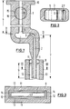
- An immersion spout 1 made of refractory ceramic material has a flow channel 2 for molten metal.
- a swamp-forming chamber 3 is designed in the immersion spout 1. This lies below an inlet area 4 of the flow channel 2, which merges into the chamber 3 from above at an opening 5.
- An overflow edge 6 is formed on the side of the chamber 3, at which the chamber 3 merges into an outlet area 7 of the flow channel 2.
- the overflow edge is rounded in order to achieve a smooth melt flow.
- the immersion spout 1 can be inserted into a mold 8 in the outlet area 7.
- An immersion zone 9 of the outlet area 7 projects into the mold 8.
- the outlet area 7 is considerably shorter than the inlet area 4.
- the sump-forming chamber 3 is substantially closer to the immersion zone 9 than the upper end 10 of the immersion spout 1, which can be connected to a metallurgical vessel.
- the mold 8 has walls 11 on the long side and walls 12 on the narrow side.
- the narrow-side walls 12 are much shorter in a thin slab mold than the long-side walls 11 (see FIG. 3).
- the flow channel 2 has a channel geometry approximating the inner cross section of the mold 8.
- the immersion spout 1 thus has the same cross-section as the mold 8 in the region of the immersion zone 9 except for the necessary long and narrow gaps 13, 14.
- the flow channel 2 in the outlet area 7 has approximately the same cross-sectional geometry as in the immersion zone 9.
- the cross section of the outlet area 7 does not change.
- the outlet area 7 tapers above the immersion zone 9 in its narrow extension.
- the channel cross-sectional geometry in the inlet area 4 can be designed independently of the cross-sectional geometry of the immersion zone 9 or the outlet area 7.
- the cross section in the inlet area 4 is approximately the same as in the outlet area 7.
- the passage channel 2 is therefore also narrow and elongated in the inlet area 4.
- the flow channel 2 in the inlet area 4 is circular in cross section (cf. FIG. 5, FIG. 7).
- the inlet area 4 could also be designed as in the exemplary embodiment according to FIGS. 1, 2.
- the inlet area 4 in FIGS. 1, 2 could also be designed as in the exemplary embodiments according to FIGS to 7.
- the cross-sectional area of the flow channel 2 in the inlet area 4 is approximately as large as the cross-sectional area of the flow channel 2 in the immersion zone 9.
- a closure and / or regulating member 15 is integrated, with which the melt flow can be controlled.
- the closure and / or regulating member 15 is arranged in the inlet area 4. 4
- the closure and / or control member 15 is provided in the chamber 3. 6
- the closure and / or regulating member 15 is provided in the outlet area 7.
- a roller-shaped rotor 16 is mounted in the immersion spout 1 as the closure and / or regulating member 15.
- the rotor 16 has a radial passage slot 17. In the open position shown in Fig. 1, the melt flow is free. If the rotor 16 is rotated about the axis 18, the melt flow is more or less interrupted.
- a rotor 19 is arranged in the chamber 3.
- the rotor 19 forms the bottom of the chamber 3 with a flattening 20.
- the rotor 19 is shown in its open position in FIG. 4. It forms the chamber 3 open to the inlet area 4 and the outlet area 7.
- the melt flow can be interrupted in whole or in part by rotating the rotor 19 about the axis 21. Part of the outer circumference of the rotor 19 moves in front of the mouth 5 of the inlet area 4 and / or the outlet area 7 above the overflow edge 6.
- the closure and / or regulating member 15 is formed by an electromagnetic device with an induction coil 22, which includes the immersion spout 1 at the outlet area 7. If an induction current flows through the coil 22, the melt is acted on in such a way that the ferrostatic pressure is reduced.
- This device can also be arranged in the region of the chamber 3.
- the functionality of the immersion nozzle described is essentially as follows: In the casting operation, 4 melt flows through the inlet area into the sump-forming chamber 3. It soothes and distributes itself in the melt sump existing in chamber 3. The melt then passes over the overflow edge 6 of the chamber 3 into the outlet area 7. It already leaves the chamber 3 at a flow width which essentially corresponds to the longitudinal wall of the mold 8. The melt flows evenly over the cross-section of the outlet area 7, distributed therein into the melt of the mold 8. The melt flows through the outlet area 7 in a substantially laminar manner in a uniform distribution over its cross-section and at essentially the same speed in all cross-sectional areas.
- the melt in the mold 8 does not have to flow over longer distances, so that also the turbulence associated with such flow is avoided.
- melt flow is to be throttled or interrupted, the closure and / or regulating member 15 is actuated.
- the immersion nozzle 1 is shown in one piece to simplify the illustration.
- the immersion nozzle can, however, be made in several parts for structural reasons or for reasons of different loads. Divisions T are indicated in FIGS. 4 and 6.
- the chamber 3 can be heated to prevent the melt from freezing there.
- the chamber 3 can be heated inductively.
Landscapes
- Engineering & Computer Science (AREA)
- Mechanical Engineering (AREA)
- Manufacturing & Machinery (AREA)
- Casting Support Devices, Ladles, And Melt Control Thereby (AREA)
- Nozzles (AREA)
- Continuous Casting (AREA)
Applications Claiming Priority (2)
| Application Number | Priority Date | Filing Date | Title |
|---|---|---|---|
| DE4319966A DE4319966A1 (de) | 1993-06-17 | 1993-06-17 | Eintauchausguß |
| DE4319966 | 1993-06-17 |
Publications (2)
| Publication Number | Publication Date |
|---|---|
| EP0630711A1 true EP0630711A1 (fr) | 1994-12-28 |
| EP0630711B1 EP0630711B1 (fr) | 1997-01-22 |
Family
ID=6490475
Family Applications (1)
| Application Number | Title | Priority Date | Filing Date |
|---|---|---|---|
| EP94104559A Expired - Lifetime EP0630711B1 (fr) | 1993-06-17 | 1994-03-23 | Busette de coulée immergée |
Country Status (5)
| Country | Link |
|---|---|
| US (1) | US5547014A (fr) |
| EP (1) | EP0630711B1 (fr) |
| JP (1) | JPH071094A (fr) |
| KR (1) | KR950000265A (fr) |
| DE (2) | DE4319966A1 (fr) |
Cited By (2)
| Publication number | Priority date | Publication date | Assignee | Title |
|---|---|---|---|---|
| WO2000056484A1 (fr) * | 1999-03-22 | 2000-09-28 | Vesuvius Crucible Company | Element refractaire et vanne rotative pour metal en fusion |
| CN1084233C (zh) * | 1995-03-21 | 2002-05-08 | 曼内斯曼股份公司 | 金属液浇注到结晶器中的方法和设备 |
Families Citing this family (7)
| Publication number | Priority date | Publication date | Assignee | Title |
|---|---|---|---|---|
| DE4344953C2 (de) * | 1993-12-27 | 1996-10-02 | Mannesmann Ag | Verfahren und Vorrichtung zum Angießen eines endabmessungsnahen Metallbandes |
| US5944261A (en) * | 1994-04-25 | 1999-08-31 | Vesuvius Crucible Company | Casting nozzle with multi-stage flow division |
| DE19512208C1 (de) * | 1995-03-21 | 1996-07-18 | Mannesmann Ag | Tauchausguß zum Gießen von Metall |
| UA51734C2 (uk) * | 1996-10-03 | 2002-12-16 | Візувіус Крусібл Компані | Занурений стакан для пропускання рідкого металу і спосіб пропускання рідкого металу через нього |
| FR2763524A1 (fr) * | 1997-05-23 | 1998-11-27 | Vesuvius France Sa | Installation pour la coulee continue d'un metal liquide, et organe pour cette installation |
| KR100711398B1 (ko) * | 2005-12-22 | 2007-04-30 | 주식회사 포스코 | 주형 침적노즐 및 이를 구비하는 연속 주조용 용융금속공급장치 |
| US7543605B1 (en) * | 2008-06-03 | 2009-06-09 | Morando Jorge A | Dual recycling/transfer furnace flow management valve for low melting temperature metals |
Citations (5)
| Publication number | Priority date | Publication date | Assignee | Title |
|---|---|---|---|---|
| DE2105881A1 (en) * | 1971-02-01 | 1972-08-24 | Mannesmann AG, 4000 Düsseldorf | Metal pouring - in continuous casting with bell-shape pouring unit feeding ingot mould |
| EP0155575A1 (fr) * | 1984-03-07 | 1985-09-25 | Concast Standard Ag | Procédé pour le réglage d'écoulement d'un liquide conductible à l'électricité spécialement d'un bain de métal de la coulée continue et dispositif pour la mise en oeuvre du procédé |
| DE3842789A1 (de) * | 1987-12-21 | 1989-07-06 | Ishikawajima Harima Heavy Ind | Giessvorrichtung fuer eine zweiwalzen-stranggiessmaschine |
| DE3809071A1 (de) * | 1988-03-18 | 1989-09-28 | Didier Werke Ag | Dreh- und/oder schieberverschluss fuer einen ausguss eines metallschmelze enthaltenden gefaesses, sowie verschlussteile fuer einen solchen verschluss |
| DE4142447A1 (de) * | 1991-06-21 | 1992-12-24 | Mannesmann Ag | Tauchgiessrohr - duennbramme |
Family Cites Families (16)
| Publication number | Priority date | Publication date | Assignee | Title |
|---|---|---|---|---|
| US3310850A (en) * | 1963-12-13 | 1967-03-28 | Rheinstahl Huettenwerke Ag | Method and apparatus for degassing and casting metals in a vacuum |
| JPS5225811A (en) * | 1975-08-22 | 1977-02-26 | Kawasaki Rozai Kk | Manufacture of burned refractory bricks |
| JPS55136550A (en) * | 1979-04-10 | 1980-10-24 | Nippon Steel Corp | Continuous casting method |
| SU1227321A1 (ru) * | 1984-11-06 | 1986-04-30 | Предприятие П/Я В-2996 | Автоматический регул тор расхода в кристаллизаторе |
| JPS61165257A (ja) * | 1985-01-16 | 1986-07-25 | Mitsubishi Heavy Ind Ltd | 連続鋳造装置における注湯装置 |
| DE3805071A1 (de) * | 1988-02-18 | 1989-08-31 | Didier Werke Ag | Abschluss- und regeleinrichtung fuer das giessen fluessiger metallschmelze |
| DE3811751A1 (de) * | 1988-04-08 | 1989-10-19 | Schloemann Siemag Ag | Tauchgiessrohr zum einleiten von metallschmelze in eine metallbandgiesskokille |
| DE3839214A1 (de) * | 1988-11-19 | 1990-05-23 | Schloemann Siemag Ag | Verfahren und vorrichtung zum einleiten von metallschmelze in eine brammenkokille |
| DE3907003A1 (de) * | 1989-03-04 | 1990-09-06 | Schloemann Siemag Ag | Verfahren und vorrichtung zum einleiten von metallschmelze in eine brammenkokille |
| JPH02258145A (ja) * | 1989-03-31 | 1990-10-18 | Ishikawajima Harima Heavy Ind Co Ltd | 双ロール式連鋳機の注湯装置 |
| DE3918228C2 (de) * | 1989-06-03 | 1996-11-07 | Schloemann Siemag Ag | Tauchgießrohr zum Einleiten von Stahlschmelze in eine Stranggießkokille |
| DE4032624A1 (de) * | 1990-10-15 | 1992-04-16 | Schloemann Siemag Ag | Tauchgiessrohr zum einleiten von stahlschmelze in eine stranggiesskokille |
| DE4104690A1 (de) * | 1991-02-15 | 1992-08-20 | Schloemann Siemag Ag | Tauchgiessrohr zum einleiten von stahlschmelze in eine stranggiesskokille |
| NZ242595A (en) * | 1991-05-23 | 1993-09-27 | Ishikawajima Harima Heavy Ind | Casting metal strip; delivery nozzle for delivering molten metal to nip rollers |
| DE4142477C2 (de) * | 1991-12-20 | 1994-06-01 | Bosch Siemens Hausgeraete | Dunstabzugsvorrichtung |
| JP3007942B2 (ja) * | 1992-04-24 | 2000-02-14 | 石川島播磨重工業株式会社 | 金属ストリップ鋳造方法及び装置 |
-
1993
- 1993-06-17 DE DE4319966A patent/DE4319966A1/de not_active Withdrawn
-
1994
- 1994-03-23 EP EP94104559A patent/EP0630711B1/fr not_active Expired - Lifetime
- 1994-03-23 DE DE59401635T patent/DE59401635D1/de not_active Expired - Fee Related
- 1994-05-04 KR KR1019940009819A patent/KR950000265A/ko not_active Withdrawn
- 1994-05-19 JP JP6139266A patent/JPH071094A/ja active Pending
- 1994-05-31 US US08/251,200 patent/US5547014A/en not_active Expired - Fee Related
Patent Citations (5)
| Publication number | Priority date | Publication date | Assignee | Title |
|---|---|---|---|---|
| DE2105881A1 (en) * | 1971-02-01 | 1972-08-24 | Mannesmann AG, 4000 Düsseldorf | Metal pouring - in continuous casting with bell-shape pouring unit feeding ingot mould |
| EP0155575A1 (fr) * | 1984-03-07 | 1985-09-25 | Concast Standard Ag | Procédé pour le réglage d'écoulement d'un liquide conductible à l'électricité spécialement d'un bain de métal de la coulée continue et dispositif pour la mise en oeuvre du procédé |
| DE3842789A1 (de) * | 1987-12-21 | 1989-07-06 | Ishikawajima Harima Heavy Ind | Giessvorrichtung fuer eine zweiwalzen-stranggiessmaschine |
| DE3809071A1 (de) * | 1988-03-18 | 1989-09-28 | Didier Werke Ag | Dreh- und/oder schieberverschluss fuer einen ausguss eines metallschmelze enthaltenden gefaesses, sowie verschlussteile fuer einen solchen verschluss |
| DE4142447A1 (de) * | 1991-06-21 | 1992-12-24 | Mannesmann Ag | Tauchgiessrohr - duennbramme |
Cited By (2)
| Publication number | Priority date | Publication date | Assignee | Title |
|---|---|---|---|---|
| CN1084233C (zh) * | 1995-03-21 | 2002-05-08 | 曼内斯曼股份公司 | 金属液浇注到结晶器中的方法和设备 |
| WO2000056484A1 (fr) * | 1999-03-22 | 2000-09-28 | Vesuvius Crucible Company | Element refractaire et vanne rotative pour metal en fusion |
Also Published As
| Publication number | Publication date |
|---|---|
| DE4319966A1 (de) | 1994-12-22 |
| DE59401635D1 (de) | 1997-03-06 |
| US5547014A (en) | 1996-08-20 |
| KR950000265A (ko) | 1995-01-03 |
| JPH071094A (ja) | 1995-01-06 |
| EP0630711B1 (fr) | 1997-01-22 |
Similar Documents
| Publication | Publication Date | Title |
|---|---|---|
| DE4142447C3 (de) | Tauchgießrohr - Dünnbramme | |
| EP0254909B1 (fr) | Busette de coulée réfractaire | |
| EP0630711B1 (fr) | Busette de coulée immergée | |
| DE2747746A1 (de) | Zwischenpfannen-giesschnauze | |
| DE4322316C1 (de) | Einlaufsystem für eine Aluminiumstranggußanlage | |
| DE2548939C2 (de) | Verfahren und Vorrichtung zum Stranggießen von Bändern | |
| DE60201539T3 (de) | Stopfenstange | |
| DE2132294A1 (de) | Verfahren und Vorrichtung zum Giessen von Metallschmelze | |
| EP0814929B1 (fr) | Busette immergee pour couler du metal | |
| DE3426107C2 (de) | Schiebeverschluß für den horizontalen Ausguß von Nichteisen-Metallschmelze enthaltenden Gefässen | |
| EP3130414B1 (fr) | Installation metallurgique de fusion, comprenant une lingotiere | |
| EP0902736B1 (fr) | Procede et dispositif de coulee de l'acier dans une rigole de coulee imergee | |
| DE4000656C2 (fr) | ||
| EP0726113B1 (fr) | Système d'entrée pour une installation de coulée continue d'aluminium | |
| DE19811957C2 (de) | Anordnung eines Tauchausgusses in einer Kokille zum Stranggießen von Brammen | |
| EP0151802B1 (fr) | Dispositif pour l'introduction de métal liquide, en particulier d'acier liquide dans une coquille de coulée continue | |
| DE19520897C1 (de) | Strangguß-Verteilerrinne | |
| DE10240491A1 (de) | Feuerfestes keramisches Tauchrohr | |
| DE19505390C2 (de) | Tauchgießrohr | |
| DE19801822C1 (de) | Verfahren und Vorrichtung zum Stranggießen von Metallen | |
| DE2224482A1 (de) | Vorrichtung zum abgiessen aluminiumberuhigter staehle im strang | |
| DE19722890A1 (de) | Tauchausguß | |
| DE3634891C1 (de) | Nachheizeinrichtung bei einer Horizontal-Stranggiessanlage | |
| DE2138394A1 (de) | Strangguss-verfahren und -vorrichtung | |
| DE2119664A1 (en) | Continuous casting process - eliminates clay deposits from the product and the need for deseaming |
Legal Events
| Date | Code | Title | Description |
|---|---|---|---|
| PUAI | Public reference made under article 153(3) epc to a published international application that has entered the european phase |
Free format text: ORIGINAL CODE: 0009012 |
|
| 17P | Request for examination filed |
Effective date: 19940408 |
|
| AK | Designated contracting states |
Kind code of ref document: A1 Designated state(s): BE DE FR GB |
|
| 17Q | First examination report despatched |
Effective date: 19950216 |
|
| GRAG | Despatch of communication of intention to grant |
Free format text: ORIGINAL CODE: EPIDOS AGRA |
|
| GRAH | Despatch of communication of intention to grant a patent |
Free format text: ORIGINAL CODE: EPIDOS IGRA |
|
| GRAH | Despatch of communication of intention to grant a patent |
Free format text: ORIGINAL CODE: EPIDOS IGRA |
|
| GRAA | (expected) grant |
Free format text: ORIGINAL CODE: 0009210 |
|
| AK | Designated contracting states |
Kind code of ref document: B1 Designated state(s): BE DE FR GB |
|
| ET | Fr: translation filed | ||
| GBT | Gb: translation of ep patent filed (gb section 77(6)(a)/1977) |
Effective date: 19970122 |
|
| REF | Corresponds to: |
Ref document number: 59401635 Country of ref document: DE Date of ref document: 19970306 |
|
| PLBE | No opposition filed within time limit |
Free format text: ORIGINAL CODE: 0009261 |
|
| STAA | Information on the status of an ep patent application or granted ep patent |
Free format text: STATUS: NO OPPOSITION FILED WITHIN TIME LIMIT |
|
| 26N | No opposition filed | ||
| PGFP | Annual fee paid to national office [announced via postgrant information from national office to epo] |
Ref country code: BE Payment date: 19980320 Year of fee payment: 5 |
|
| PG25 | Lapsed in a contracting state [announced via postgrant information from national office to epo] |
Ref country code: BE Free format text: LAPSE BECAUSE OF NON-PAYMENT OF DUE FEES Effective date: 19990331 |
|
| BERE | Be: lapsed |
Owner name: DIDIER-WERKE A.G. Effective date: 19990331 |
|
| PGFP | Annual fee paid to national office [announced via postgrant information from national office to epo] |
Ref country code: GB Payment date: 20000222 Year of fee payment: 7 |
|
| PGFP | Annual fee paid to national office [announced via postgrant information from national office to epo] |
Ref country code: DE Payment date: 20000224 Year of fee payment: 7 |
|
| PGFP | Annual fee paid to national office [announced via postgrant information from national office to epo] |
Ref country code: FR Payment date: 20000225 Year of fee payment: 7 |
|
| PG25 | Lapsed in a contracting state [announced via postgrant information from national office to epo] |
Ref country code: GB Free format text: LAPSE BECAUSE OF NON-PAYMENT OF DUE FEES Effective date: 20010323 |
|
| GBPC | Gb: european patent ceased through non-payment of renewal fee |
Effective date: 20010323 |
|
| PG25 | Lapsed in a contracting state [announced via postgrant information from national office to epo] |
Ref country code: FR Free format text: LAPSE BECAUSE OF NON-PAYMENT OF DUE FEES Effective date: 20011130 |
|
| REG | Reference to a national code |
Ref country code: FR Ref legal event code: ST |
|
| PG25 | Lapsed in a contracting state [announced via postgrant information from national office to epo] |
Ref country code: DE Free format text: LAPSE BECAUSE OF NON-PAYMENT OF DUE FEES Effective date: 20020101 |