EP0630773A1 - Dispositif pour transmettre un mouvement angulaire entre deux éléments en rotation avec des axes obliques, en particulier pour les buses d'aération de véhicules automobiles - Google Patents
Dispositif pour transmettre un mouvement angulaire entre deux éléments en rotation avec des axes obliques, en particulier pour les buses d'aération de véhicules automobiles Download PDFInfo
- Publication number
- EP0630773A1 EP0630773A1 EP94109166A EP94109166A EP0630773A1 EP 0630773 A1 EP0630773 A1 EP 0630773A1 EP 94109166 A EP94109166 A EP 94109166A EP 94109166 A EP94109166 A EP 94109166A EP 0630773 A1 EP0630773 A1 EP 0630773A1
- Authority
- EP
- European Patent Office
- Prior art keywords
- rod
- portions
- hinges
- shaped
- valve
- Prior art date
- Legal status (The legal status is an assumption and is not a legal conclusion. Google has not performed a legal analysis and makes no representation as to the accuracy of the status listed.)
- Granted
Links
Images



Classifications
-
- F—MECHANICAL ENGINEERING; LIGHTING; HEATING; WEAPONS; BLASTING
- F16—ENGINEERING ELEMENTS AND UNITS; GENERAL MEASURES FOR PRODUCING AND MAINTAINING EFFECTIVE FUNCTIONING OF MACHINES OR INSTALLATIONS; THERMAL INSULATION IN GENERAL
- F16C—SHAFTS; FLEXIBLE SHAFTS; ELEMENTS OR CRANKSHAFT MECHANISMS; ROTARY BODIES OTHER THAN GEARING ELEMENTS; BEARINGS
- F16C11/00—Pivots; Pivotal connections
- F16C11/04—Pivotal connections
- F16C11/12—Pivotal connections incorporating flexible connections, e.g. leaf springs
-
- B—PERFORMING OPERATIONS; TRANSPORTING
- B60—VEHICLES IN GENERAL
- B60H—ARRANGEMENTS OF HEATING, COOLING, VENTILATING OR OTHER AIR-TREATING DEVICES SPECIALLY ADAPTED FOR PASSENGER OR GOODS SPACES OF VEHICLES
- B60H1/00—Heating, cooling or ventilating devices
- B60H1/00642—Control systems or circuits; Control members or indication devices for heating, cooling or ventilating devices
- B60H1/00814—Control systems or circuits characterised by their output, for controlling particular components of the heating, cooling or ventilating installation
- B60H1/00821—Control systems or circuits characterised by their output, for controlling particular components of the heating, cooling or ventilating installation the components being ventilating, air admitting or air distributing devices
- B60H1/00835—Damper doors, e.g. position control
- B60H1/00857—Damper doors, e.g. position control characterised by the means connecting the initiating means, e.g. control lever, to the damper door
-
- B—PERFORMING OPERATIONS; TRANSPORTING
- B60—VEHICLES IN GENERAL
- B60H—ARRANGEMENTS OF HEATING, COOLING, VENTILATING OR OTHER AIR-TREATING DEVICES SPECIALLY ADAPTED FOR PASSENGER OR GOODS SPACES OF VEHICLES
- B60H1/00—Heating, cooling or ventilating devices
- B60H1/34—Nozzles; Air-diffusers
- B60H1/3414—Nozzles; Air-diffusers with means for adjusting the air stream direction
-
- B—PERFORMING OPERATIONS; TRANSPORTING
- B60—VEHICLES IN GENERAL
- B60H—ARRANGEMENTS OF HEATING, COOLING, VENTILATING OR OTHER AIR-TREATING DEVICES SPECIALLY ADAPTED FOR PASSENGER OR GOODS SPACES OF VEHICLES
- B60H1/00—Heating, cooling or ventilating devices
- B60H1/34—Nozzles; Air-diffusers
- B60H2001/3464—Details of hinges
-
- B—PERFORMING OPERATIONS; TRANSPORTING
- B60—VEHICLES IN GENERAL
- B60H—ARRANGEMENTS OF HEATING, COOLING, VENTILATING OR OTHER AIR-TREATING DEVICES SPECIALLY ADAPTED FOR PASSENGER OR GOODS SPACES OF VEHICLES
- B60H1/00—Heating, cooling or ventilating devices
- B60H1/34—Nozzles; Air-diffusers
- B60H2001/3471—Details of actuators
- B60H2001/3478—Details of actuators acting on additional damper doors
Definitions
- the present invention relates to a device for transmitting angular motion between two rotating elements with oblique axes.
- the device according to the invention is suitable for various uses, one of its typical applications concerns the air vents of motor vehicles, where said device is used, by way of example, to transmit the angular motion from the rotating control knob, located on the front base of the vent, to the butterfly valve which adjusts and interrupts the air flow and is located in the manifold of the vent.
- angular motion is transmitted from the rotating control knob to the cutoff and adjustment valve by means of conventional kinematic systems that include connecting rods with spherical heads, cranks, slot links optionally associated with bevel gear pairs when the axis of the knob and the axis of the valve are at right angles to each other.
- said kinematic systems are subject to breakages or jammings and generally wear tends to stiffen the rotary motion of the control knob.
- the aim of the present invention is to eliminate this and other drawbacks and within the scope of this general purpose the present invention has the important object of providing a transmission device which is economically advantageous from the point of view of manufacturing and assembly costs, has very limited dimensions and allows to transmit angular motion between two rotating elements regardless of their mutual arrangement.
- the device according to the invention allows to transmit angular motion from a rotating control knob to a flow cutoff and adjustment valve whose respective rotation axes are oblique or co-planar but incident.
- Another important object of the invention is to provide a device for transmitting angular motion that can be obtained by molding polymeric thermoplastic material without requiring any further processing.
- the device according to the invention is constituted by a single transmission rod formed by several rod portions which are mutually connected by lamellar hinges; the respective hinging axes of at least two preferably consecutive hinges are mutually perpendicular.
- the rod is made of thermoplastic polymeric material and the laminar hinges are obtained by molding them monolithically with the portions that compose the rod.
- the end portions can be disk-shaped or flange-shaped and the like and can have a prism-shaped bore to key directly with a corresponding prism-shaped hub of the rotating element (knob and/or valve).
- one or both end portions can be shaped like a toothed sector to mesh with corresponding toothed sectors of the knob and/or shaft of the valve.
- the reference numeral 10 designates an air vent for motor vehicles which comprises a manifold 11 that is meant to be connected to the air delivery duct, a flow orientation grille 12 and a front base 13.
- the manifold 11 is elbow-shaped and has, at its inlet section, a butterfly valve 14 for adjusting and interrupting the air flow.
- the valve 14 is rotatably suspended about an axis "a" which is perpendicular to the axis of the manifold within the section that contains the valve.
- a is perpendicular to the axis of the manifold within the section that contains the valve.
- a is perpendicular to the axis of the manifold within the section that contains the valve.
- a knob 15 At the front part of the vent and to the side of the manifold 11 there is a knob 15 for actuating the valve 14 which protrudes to allow grip from a slot 16 of the base 13.
- the knob 15 is rotatably suspended about an axis "b" which is perpendicular to the axis of the manifold in the section that contains the knob.
- the transmission device according to the invention is arranged between the knob 15 and the valve 14.
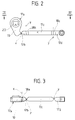
- Said device is substantially constituted by a single transmission rod formed by rod portions 17a-17b-17c-17d which are mutually connected by laminar hinges 18a-18b-18c; the respective hinging axes x-y of at least two of said hinges, preferably consecutive ones such as 18a-18b, are mutually perpendicular.
- the above mentioned laminar hinges are obtained in a known manner by tapering the ends of the rod portions so as to form 45 o planes until said ends are reduced to the thickness of a film measuring 2-4 tenths of a millimeter, which constitutes the hinge.
- the transmission rod 17 is made of thermoplastic polymeric material and the laminar hinges 18a-18b-18c are obtained by molding monolithically with the portions 17a-17b-17c-17d.
- the end portion 17a is flange-shaped, with a crank-like extension 19 that ends with the hinge 18a for articulation to the adjacent portion 17b, whose hinging axis x is parallel to the rotation axis "a" of the valve 14.
- In said flange there is a central prism-shaped bore 20 used to key the end portion 17a directly with a corresponding prism-shaped hub 21 of the valve 14.
- the end portion 17d is in turn shaped like an eyelet and engages an eccentric pivot 22 supported by the knob 15.
- the hinging axes y of the intermediate hinges 18b-18c are mutually parallel and lie at right angles to the axes "a" and/or "b” for the rotation of the valve 14 and respectively of the knob 15 so that the transmission rod 17 can assume a curved configuration (figure 1) that is suitable to compensate any backward motion of the hub 21 with respect to the eccentric pivot 22, said backward motion being due to the angled arrangement of the manifold 11.
- the manifold 111 of the vent 110 has a substantially curved axial configuration, and the valve 114 is rotatable about an axis "c" which lies at right angles to the axis "b" of the control knob 115 that protrudes from the base 113.
- the transmission device 117 is formed by five rod portions 117a-117b-117c-117d-117e connected by two pairs of laminar hinges 118a-118b and 118c-118d with mutually perpendicular hinging axes x-y.
- the end portion 117a which also has a prism-shaped keying bore 120, is flange-shaped and has a crank-like extension 119 that ends with the hinge 118a, whose hinging axis y is parallel to the rotation axis "c" of the valve 114.
- the end portion 117e is shaped like a toothed sector, is rotatably supported by a pivot P, and meshes with a corresponding toothed sector 115a of the knob 115.
- the axis x of the hinge 118d which connects said end portion 117e to the adjacent portion 117d is parallel to the axis "d" of the pivot P.
- the intermediate portion 117c forms an elbow in the vertical plane that contains the rotation axis "c" of the valve in order to compensate for the difference in elevation between the pivot P and the prism-shaped hub of the valve 114.
- the transmission device according to the invention can be structured in various manners within a general inventive concept which entails the use of an articulated rod which is formed by said several portions that have any profile and are mutually connected by hinges formed monolithically with said portions, the respective hinging axes x-y of at least two consecutive hinges being mutually perpendicular.
Landscapes
- Engineering & Computer Science (AREA)
- Mechanical Engineering (AREA)
- General Engineering & Computer Science (AREA)
- Physics & Mathematics (AREA)
- Thermal Sciences (AREA)
- Air-Flow Control Members (AREA)
- Mechanically-Actuated Valves (AREA)
- General Details Of Gearings (AREA)
- Electric Propulsion And Braking For Vehicles (AREA)
- Motor Or Generator Cooling System (AREA)
Applications Claiming Priority (2)
| Application Number | Priority Date | Filing Date | Title |
|---|---|---|---|
| ITTO930450A IT1261306B (it) | 1993-06-22 | 1993-06-22 | Dispositivo di rinvio del moto angolare tra due organi girevoli ad assi sghembi, particolarmente per bocchette di ventilazione di autoveicoli |
| ITTO930450 | 1993-06-22 |
Publications (2)
| Publication Number | Publication Date |
|---|---|
| EP0630773A1 true EP0630773A1 (fr) | 1994-12-28 |
| EP0630773B1 EP0630773B1 (fr) | 1997-05-21 |
Family
ID=11411568
Family Applications (1)
| Application Number | Title | Priority Date | Filing Date |
|---|---|---|---|
| EP94109166A Expired - Lifetime EP0630773B1 (fr) | 1993-06-22 | 1994-06-15 | Dispositif pour transmettre un mouvement angulaire entre deux éléments en rotation avec des axes obliques, en particulier pour les buses d'aération de véhicules automobiles |
Country Status (3)
| Country | Link |
|---|---|
| EP (1) | EP0630773B1 (fr) |
| DE (1) | DE69403279T2 (fr) |
| IT (1) | IT1261306B (fr) |
Cited By (5)
| Publication number | Priority date | Publication date | Assignee | Title |
|---|---|---|---|---|
| EP1288034A1 (fr) * | 2001-09-04 | 2003-03-05 | Dr.Ing. h.c.F. Porsche Aktiengesellschaft | Buse d'aération pour montant de véhicule |
| WO2010011517A1 (fr) | 2008-07-24 | 2010-01-28 | Honda Motor Co., Ltd. | Soupape de fermeture actionnée par engrenage pour un système de ventilation |
| US9758018B2 (en) | 2013-09-10 | 2017-09-12 | Illinois Tool Works Inc. | Control element and assembly for an air vent as well as method for mounting a control element |
| US20220041036A1 (en) * | 2020-08-07 | 2022-02-10 | Mahle International Gmbh | Torque transmission device |
| JP2022134468A (ja) * | 2021-03-03 | 2022-09-15 | フタバ産業株式会社 | 車両用アンダーカバー及び車両用アンダーカバーの製造方法 |
Families Citing this family (1)
| Publication number | Priority date | Publication date | Assignee | Title |
|---|---|---|---|---|
| KR20200117483A (ko) * | 2019-04-04 | 2020-10-14 | 현대자동차주식회사 | 에어벤트 장치 |
Citations (4)
| Publication number | Priority date | Publication date | Assignee | Title |
|---|---|---|---|---|
| US3388611A (en) * | 1966-01-25 | 1968-06-18 | Gen Motors Corp | Control linkage |
| US3405539A (en) * | 1966-06-13 | 1968-10-15 | Gen Motors Corp | Flexible rotary joint |
| EP0180053A2 (fr) * | 1984-10-30 | 1986-05-07 | FOGGINI PROGETTI S.r.l. | Tringlerie, en particulier pour les ouvertures d'air conditionné de véhicules à moteur |
| FR2671520A1 (fr) * | 1991-01-11 | 1992-07-17 | Renault | Aerateur pour systemes de ventilation et de climatisation. |
-
1993
- 1993-06-22 IT ITTO930450A patent/IT1261306B/it active IP Right Grant
-
1994
- 1994-06-15 EP EP94109166A patent/EP0630773B1/fr not_active Expired - Lifetime
- 1994-06-15 DE DE69403279T patent/DE69403279T2/de not_active Expired - Fee Related
Patent Citations (4)
| Publication number | Priority date | Publication date | Assignee | Title |
|---|---|---|---|---|
| US3388611A (en) * | 1966-01-25 | 1968-06-18 | Gen Motors Corp | Control linkage |
| US3405539A (en) * | 1966-06-13 | 1968-10-15 | Gen Motors Corp | Flexible rotary joint |
| EP0180053A2 (fr) * | 1984-10-30 | 1986-05-07 | FOGGINI PROGETTI S.r.l. | Tringlerie, en particulier pour les ouvertures d'air conditionné de véhicules à moteur |
| FR2671520A1 (fr) * | 1991-01-11 | 1992-07-17 | Renault | Aerateur pour systemes de ventilation et de climatisation. |
Cited By (11)
| Publication number | Priority date | Publication date | Assignee | Title |
|---|---|---|---|---|
| EP1288034A1 (fr) * | 2001-09-04 | 2003-03-05 | Dr.Ing. h.c.F. Porsche Aktiengesellschaft | Buse d'aération pour montant de véhicule |
| US6808451B2 (en) | 2001-09-04 | 2004-10-26 | Dr. Ing. H.C.F. Porsche Aktiengesellschaft | Air flow arrangement |
| WO2010011517A1 (fr) | 2008-07-24 | 2010-01-28 | Honda Motor Co., Ltd. | Soupape de fermeture actionnée par engrenage pour un système de ventilation |
| JP2011529168A (ja) * | 2008-07-24 | 2011-12-01 | 本田技研工業株式会社 | 換気システムのギア駆動遮断弁 |
| EP2326462A4 (fr) * | 2008-07-24 | 2011-12-07 | Honda Motor Co Ltd | Soupape de fermeture actionnée par engrenage pour un système de ventilation |
| RU2481197C2 (ru) * | 2008-07-24 | 2013-05-10 | Хонда Мотор Ко., Лтд. | Шестеренный запорный клапан для вентиляционной системы |
| US9758018B2 (en) | 2013-09-10 | 2017-09-12 | Illinois Tool Works Inc. | Control element and assembly for an air vent as well as method for mounting a control element |
| US20220041036A1 (en) * | 2020-08-07 | 2022-02-10 | Mahle International Gmbh | Torque transmission device |
| CN114060592A (zh) * | 2020-08-07 | 2022-02-18 | 马勒国际公司 | 转矩传递装置 |
| JP2022134468A (ja) * | 2021-03-03 | 2022-09-15 | フタバ産業株式会社 | 車両用アンダーカバー及び車両用アンダーカバーの製造方法 |
| JP7538066B2 (ja) | 2021-03-03 | 2024-08-21 | フタバ産業株式会社 | 車両用アンダーカバー及び車両用アンダーカバーの製造方法 |
Also Published As
| Publication number | Publication date |
|---|---|
| ITTO930450A1 (it) | 1994-12-22 |
| ITTO930450A0 (it) | 1993-06-22 |
| IT1261306B (it) | 1996-05-14 |
| DE69403279D1 (de) | 1997-06-26 |
| DE69403279T2 (de) | 1997-10-02 |
| EP0630773B1 (fr) | 1997-05-21 |
Similar Documents
| Publication | Publication Date | Title |
|---|---|---|
| US5470276A (en) | Diffuser air outlet | |
| US5235866A (en) | Rotary temperature control device | |
| EP1375217B1 (fr) | Buse d'aération | |
| US5746651A (en) | Eyeball outlet assembly | |
| US20130078900A1 (en) | Air Outlet Directional Flow Controller with Integrated Shut-Off Door | |
| EP0622257B1 (fr) | Buse de délivrance d'air pour véhicules à moteur | |
| EP0630773B1 (fr) | Dispositif pour transmettre un mouvement angulaire entre deux éléments en rotation avec des axes obliques, en particulier pour les buses d'aération de véhicules automobiles | |
| US5056420A (en) | Grilles for air conditioning | |
| WO2004043720A2 (fr) | Orifice d'evacuation d'un conduit d'air avec commande des volets au moyen d'une manette | |
| EP0978398A2 (fr) | Sortie d'air à double cylindre | |
| EP0180053A2 (fr) | Tringlerie, en particulier pour les ouvertures d'air conditionné de véhicules à moteur | |
| US5238448A (en) | Air-conditioning grille | |
| US2630692A (en) | Flexible coupling | |
| US6176775B1 (en) | Fresh air nozzle device for a vehicle | |
| EP0707992A1 (fr) | Base pour délivrer et orienter le flux d'air conditionné dans des véhicules automobiles | |
| US5129858A (en) | Air-conditioning grille | |
| US7371161B2 (en) | Sliding film valve driven at edge | |
| US3060832A (en) | Louver vane assembly | |
| US4777870A (en) | Adjustable air sweep mechanism for a room air conditioner | |
| US4635395A (en) | Louver assembly particularly useful for air-conditioning units or other like appliances | |
| US4656880A (en) | Control-motion transmission assembly for air control system of automotive vehicle | |
| EP1312494A1 (fr) | Appareil de climatisation d'un véhicule comprenant un membre de régulation en forme de plaque pour contrôler un flux d'air | |
| EP0405379A1 (fr) | Diffuseur orientable, en particulier pour les systÀ¨mes de climatisation de véhicules à moteur | |
| EP0433245B1 (fr) | Dispositif pour commander des parties mobiles d'un système de climatisation de véhicule automobile | |
| KR200252012Y1 (ko) | 자동차 냉난방장치의 에어벤트 윙 구조 |
Legal Events
| Date | Code | Title | Description |
|---|---|---|---|
| PUAI | Public reference made under article 153(3) epc to a published international application that has entered the european phase |
Free format text: ORIGINAL CODE: 0009012 |
|
| AK | Designated contracting states |
Kind code of ref document: A1 Designated state(s): DE FR GB |
|
| 17P | Request for examination filed |
Effective date: 19950408 |
|
| GRAG | Despatch of communication of intention to grant |
Free format text: ORIGINAL CODE: EPIDOS AGRA |
|
| 17Q | First examination report despatched |
Effective date: 19960627 |
|
| GRAH | Despatch of communication of intention to grant a patent |
Free format text: ORIGINAL CODE: EPIDOS IGRA |
|
| GRAH | Despatch of communication of intention to grant a patent |
Free format text: ORIGINAL CODE: EPIDOS IGRA |
|
| GRAA | (expected) grant |
Free format text: ORIGINAL CODE: 0009210 |
|
| AK | Designated contracting states |
Kind code of ref document: B1 Designated state(s): DE FR GB |
|
| REF | Corresponds to: |
Ref document number: 69403279 Country of ref document: DE Date of ref document: 19970626 |
|
| ET | Fr: translation filed | ||
| PLBE | No opposition filed within time limit |
Free format text: ORIGINAL CODE: 0009261 |
|
| STAA | Information on the status of an ep patent application or granted ep patent |
Free format text: STATUS: NO OPPOSITION FILED WITHIN TIME LIMIT |
|
| 26N | No opposition filed | ||
| PGFP | Annual fee paid to national office [announced via postgrant information from national office to epo] |
Ref country code: GB Payment date: 19980615 Year of fee payment: 5 |
|
| PGFP | Annual fee paid to national office [announced via postgrant information from national office to epo] |
Ref country code: FR Payment date: 19980616 Year of fee payment: 5 |
|
| PGFP | Annual fee paid to national office [announced via postgrant information from national office to epo] |
Ref country code: DE Payment date: 19980715 Year of fee payment: 5 |
|
| PG25 | Lapsed in a contracting state [announced via postgrant information from national office to epo] |
Ref country code: GB Free format text: LAPSE BECAUSE OF NON-PAYMENT OF DUE FEES Effective date: 19990615 |
|
| PG25 | Lapsed in a contracting state [announced via postgrant information from national office to epo] |
Ref country code: FR Free format text: THE PATENT HAS BEEN ANNULLED BY A DECISION OF A NATIONAL AUTHORITY Effective date: 19990630 |
|
| GBPC | Gb: european patent ceased through non-payment of renewal fee |
Effective date: 19990615 |
|
| PG25 | Lapsed in a contracting state [announced via postgrant information from national office to epo] |
Ref country code: DE Free format text: LAPSE BECAUSE OF NON-PAYMENT OF DUE FEES Effective date: 20000503 |
|
| REG | Reference to a national code |
Ref country code: FR Ref legal event code: ST |