EP0631032B1 - Vollfrontseiten-Vortriebsmaschine - Google Patents
Vollfrontseiten-Vortriebsmaschine Download PDFInfo
- Publication number
- EP0631032B1 EP0631032B1 EP94401323A EP94401323A EP0631032B1 EP 0631032 B1 EP0631032 B1 EP 0631032B1 EP 94401323 A EP94401323 A EP 94401323A EP 94401323 A EP94401323 A EP 94401323A EP 0631032 B1 EP0631032 B1 EP 0631032B1
- Authority
- EP
- European Patent Office
- Prior art keywords
- shield
- flap
- tunnelling machine
- machine according
- flaps
- Prior art date
- Legal status (The legal status is an assumption and is not a legal conclusion. Google has not performed a legal analysis and makes no representation as to the accuracy of the status listed.)
- Expired - Lifetime
Links
- 230000005641 tunneling Effects 0.000 title description 2
- 230000000694 effects Effects 0.000 claims abstract description 11
- 230000002093 peripheral effect Effects 0.000 claims abstract description 11
- 230000003100 immobilizing effect Effects 0.000 claims description 2
- 230000001747 exhibiting effect Effects 0.000 claims 1
- 238000005520 cutting process Methods 0.000 abstract description 9
- 238000000605 extraction Methods 0.000 abstract 2
- 238000004519 manufacturing process Methods 0.000 abstract 1
- 238000005192 partition Methods 0.000 description 23
- 238000003307 slaughter Methods 0.000 description 15
- 230000007246 mechanism Effects 0.000 description 6
- 238000006073 displacement reaction Methods 0.000 description 5
- 239000002689 soil Substances 0.000 description 5
- 230000008901 benefit Effects 0.000 description 3
- 230000000295 complement effect Effects 0.000 description 3
- 238000003466 welding Methods 0.000 description 3
- 239000012530 fluid Substances 0.000 description 2
- 239000007788 liquid Substances 0.000 description 2
- 230000033001 locomotion Effects 0.000 description 2
- 238000003754 machining Methods 0.000 description 2
- 239000000463 material Substances 0.000 description 2
- 125000006850 spacer group Chemical group 0.000 description 2
- 230000006978 adaptation Effects 0.000 description 1
- 230000005540 biological transmission Effects 0.000 description 1
- 230000006835 compression Effects 0.000 description 1
- 238000007906 compression Methods 0.000 description 1
- 230000001419 dependent effect Effects 0.000 description 1
- 238000001035 drying Methods 0.000 description 1
- 210000001061 forehead Anatomy 0.000 description 1
- 230000005484 gravity Effects 0.000 description 1
- 238000005259 measurement Methods 0.000 description 1
- 238000000034 method Methods 0.000 description 1
- 230000004048 modification Effects 0.000 description 1
- 238000012986 modification Methods 0.000 description 1
- 230000035515 penetration Effects 0.000 description 1
- 239000011435 rock Substances 0.000 description 1
- 238000007789 sealing Methods 0.000 description 1
- 238000009416 shuttering Methods 0.000 description 1
- 239000010802 sludge Substances 0.000 description 1
- 230000009466 transformation Effects 0.000 description 1
- 230000007704 transition Effects 0.000 description 1
Images


Classifications
-
- E—FIXED CONSTRUCTIONS
- E21—EARTH OR ROCK DRILLING; MINING
- E21D—SHAFTS; TUNNELS; GALLERIES; LARGE UNDERGROUND CHAMBERS
- E21D9/00—Tunnels or galleries, with or without linings; Methods or apparatus for making thereof; Layout of tunnels or galleries
- E21D9/06—Making by using a driving shield, i.e. advanced by pushing means bearing against the already placed lining
- E21D9/08—Making by using a driving shield, i.e. advanced by pushing means bearing against the already placed lining with additional boring or cutting means other than the conventional cutting edge of the shield
- E21D9/0875—Making by using a driving shield, i.e. advanced by pushing means bearing against the already placed lining with additional boring or cutting means other than the conventional cutting edge of the shield with a movable support arm carrying cutting tools for attacking the front face, e.g. a bucket
- E21D9/0879—Making by using a driving shield, i.e. advanced by pushing means bearing against the already placed lining with additional boring or cutting means other than the conventional cutting edge of the shield with a movable support arm carrying cutting tools for attacking the front face, e.g. a bucket the shield being provided with devices for lining the tunnel, e.g. shuttering
Definitions
- the present invention relates to a digging tunnel boring machine full section front, of the type described in the preamble to claim 1.
- a TBM of this type is known from document DE-A-1966242.
- This TBM has the disadvantages that the flap mounting mode allows only one tilt limited and as well as a low angle of cut of the flaps and involves an obstruction of the flow paths of cuttings.
- the object of the present invention is to propose a tunnel boring machine which overcomes the aforementioned drawbacks of tunnel boring machines known.
- the TBM according to the invention has the features that are set out in the characterizing part of the claim.
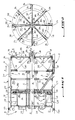
- the sign reference T designates a device or "tunnel boring machine", planned to dig in the ground S galleries such that the one which is designated in G.
- the tunnel boring machine T is this commonly known as a tunnel boring machine full face or felling shield full section.
- the TBM has a body 1 of form substantially cylindrical and whose cross-section transverse, that is to say along a plane perpendicular to its longitudinal axis XX ', is roughly almost identical to the section of the gallery or tunnel G which is carried out in soil S.
- the section of this gallery G can be modified and in particular enlarged, using equipment or tools any following tunnel boring machine T as measurement of its advance in soil S.
- the progression or advance in the floor of tunnel boring machine T runs from left to right, as indicated by arrow A.
- the orientation in the ground of the advance or advance A of the tunnel boring machine T corresponds to a trajectory planned for gallery G, and which is at least in the straight sections of this gallery G, substantially parallel or tangent to the axis XX ′.
- the body 1 has on the one hand an end 11 called "front”, and on the other hand an end 12 called "rear”.
- the end before 11 comes opposite and in contact with a front of size F of gallery G, i.e. of an area of the ground S substantially perpendicular X-X ', and from which matter (earth, stones, rocks, ...) must be torn off to advance the following tunnel boring machine T AT.
- Such a wrenching operation is, in the case of a at least full-size tunnel boring machine, called slaughter.
- slaughter the size F front progresses along A, and the tunnel boring machine T follows this progression, moving to continue digging gallery G.
- shoring elements commonly called “segments” such as those designated in B on the Figure 1 and which often consist of precast and push-in concrete elements hydraulic or concreted as it advances in the case of galleries with large sections, are placed behind the rear end 12 of the body 1 in gallery G, to consolidate it.
- the slaughter carried out by TBM generates a certain quantities of spoil, i.e. material torn from front F, and that these cuttings must be evacuated using an appropriate system from the gallery G, through the rear end 12 of the body 1.
- the periphery of the body 1 defines, at its front end 11, a peripheral cutter 110 inside which a felling shield 130 is rotatably mounted.
- the shield 130 of the tunnel boring machine T is mounted in the body 1 so that it can rotate around an axis substantially parallel to X-X ', and preferably confused with this one.
- the shield slaughterhouse 130 is made integral in rotation with a drive mechanism 3, while a device for displacement is also planned to advance the body 1 following the envisaged trajectory of the gallery G.
- TBM T is equipped with a body displacement device 1 following the advance of the cut face F of the gallery.
- This device which can be of any conventional type appropriate, will not be described here.
- the shield 130 comprises at minus one section (designated by the numerical references 141 to 148 in the figures) able to pivot around a radial axis of body 1 and on which one or more tools 14 are arranged so that the angle tilt of these tools can be adjusted by relative to the longitudinal direction X-X 'of the body 1 due to the pivoting of the shutter around its axis, and / or the shield has at least one opening (designated by the references 161 to 168) opening into front view of size F and closable by at least a flap (141 to 148, respectively) able to pivot around a radial axis of the body 1 under the effect of one or several cylinders or the like, so that the area of the opening (161-168) in a plane perpendicular to the longitudinal direction X-X 'of the body 1, can be adjusted, preferably even during rotation of the shield.
- both main characteristics set out above the invention aim to solve the same problem technique, namely the adaptation of the shield 130 to the size F front structure (either by adjusting the machining angle of the tools 14 either by modification of the opening for the passage of cuttings towards the interior of the body 1) as the advancement of the tunnel boring machine T in the gallery G which he digs, a tunnel boring machine T visible in FIGS. 1, 2 and 4 to 9 which combines these two characteristics, now be described. Nevertheless, it is clear that a tunnel borer independently presenting one or the other of these characteristics, also conforms to the invention.
- the shield 130 is made up of at least three components, and more precisely by eight flaps 141 to 148 which are integral in rotation with a central shaft 15 making part of the body 1.
- the tree 15 which has a shape roughly cylindrical and extending concentrically at X-X ', is mounted in body 1 using bearings rotation guide 151, 152 and 153, themselves installed in transverse partitions 251, 252 and 253 of body 1, respectively.
- Partitions 251, 252 and 253 which extend approximately perpendicular to X-X ', are arranged so that the end of the shaft central 15 which is integral with the shield 130 is in cantilevered.
- the partition 251 which is arranged at near the rear end 12, as well as the partition 252, define inside the body 1 a zone or airlock which allows to isolate the gallery G from the inner part of the body 1 located between the front of size F and the transverse partition 252. Thanks to this arrangement, it is possible to vary the pressure compressed air inside the tunnel boring machine T, by example using compression devices.
- a control cabin 26 is provided between the partitions cross 251 and 252. This cabin has a door 261 of access by gallery G, as well as a door 262 to access the front end 11 of the body 1. Good safe, doors 261 and 262 of the control cabin 26 can be hermetically sealed.
- the rotational drive of the shaft 15 around the axis XX ' is carried out using 32 motors arranged in appropriate compartments of the area defined by the transverse partitions 251 and 252.
- the output shaft of a motor 32 which extends approximately parallel to X-X ', is provided with a toothed pinion 33, which drives through a gear, a transmission chain 34 or the like, a wheel central tooth 35 fixed on the shaft 15.
- a toothed pinion 331 is rotatably mounted on the transverse partition 252, in order to balance the efforts within the drive mechanism 3.
- the reference numeral general 4 designates a cuttings evacuation system outside the body 1.
- the system 4 comprises chain conveyors in series 41, 42 and 43, which form together a discontinuous chain going roughly from the front end 11 to the rear end 12 of the body 1.
- the chain conveyor 41 which is diametrically opposite to the control cabin 26, is arranged so that the cuttings torn from the front of size F can be grouped under the effect of gravity, towards the upper surface of this conveyor 41.
- the conveyor 42 extends from the end of the conveyor 41 opposite the slaughter shield 130, up to inside the area defined by partitions 251 and 252, and therefore crosses the partitions 252 and 253.
- a hermetically closable door 272 is provided at the level of the partition 252, to insulate the passage opening of the conveyor 42 through this partition.
- this door and a other door 271 are illustrated both in their shutter position (right) and in their position opening record.
- the body 1 has an internal envelope 2 and an external envelope 17.
- the external envelope 17 which includes in particular the peripheral cutter 110 at level of the front end 11, is housed in the gallery G.
- the internal envelope 2 which is concentrically mounted in the outer casing 17, constitutes the peripheral wall of the zone defined by the transverse partitions 251 and 252.
- These partitions as well as the partition 253 are fixed for example by welding in the internal envelope 2 of the body 1, this the latter having a substantially cylindrical shape and extending from inside the cutter 110 to the transverse partition 251.
- the envelope outer 17 and inner shell 2 are equipped with positioning and immobilization means 217 relative, thanks to which the angular position of the inner envelope 2 relative to the outer envelope 17, and therefore the angular position in the gallery G of the control cabin 26 and the system outlet 4 in gallery G, can be adjusted and determined precisely, by rotating around X-X ', or by immobilizing in rotation, the inner envelope 2 relative to the outer envelope 17.
- the parts of a tunnel boring machine integral with the slaughter shield tend to rotate the interior of the excavated gallery, which is not desirable.
- the functional elements of the tunnel boring machine T can be replaced in a position where their functioning is optimal, and then maintained in this position.
- These means 217 can for example consist of peripheral teeth which cooperates with one or more motorized pinions and lockable.
- the reference numeral 127 designates relocation means such as for example cylinders, which allow the TBM to be positioned correctly compared to the trajectory planned for gallery G.
- These means of relocation 127 are here cylinders or the like which may stress the rear end 12 of the body 1 at its periphery and more particularly of its envelope external 17 so that permanently the longitudinal axis XX ' of tunnel boring machine T is substantially tangent to the trajectory planned for gallery G.
- the relocation means 27 act on the outer envelope 17 of the body 1 because it is very high rigidity, and includes the cutting edge before 110.
- the reference numeral 177 designates one of the spacers that allow the assembly of the envelope external 17 of body 1, and more particularly the assembly of the cutting edge 110 and the envelope 17 proper. It goes without saying that a plurality spacers 177 are provided on the periphery of the outer envelope 17, so that it is sufficiently rigid and has dimensions along X-X ' appropriate.
- each shutters 141 to 148 of the shield 130 is mounted on the body 1 via three joints, respectively designated at 154, 114 and 54. Thanks to these joints 154, 114 and 54, each flap can pivot between an open state ( Figures 1 and 2) or substantially only the section of this section (141-148) is opposite the size F front, and a closed state ( Figures 8 and 9) in which the shield 130 isolates the interior of the body 1, preferably hermetically, relative to the size F front.
- each flap is arranged in alignment in the direction of a radius of the central shaft 15, and therefore of the body 1, in the vicinity of the face size F, to jointly define the axis pivoting of the corresponding flap (141 to 148).
- the joints 114 and 154 which are regularly distributed around the periphery of the shield 130 and the central shaft 15 respectively, are aligned two by two along a radial axis or radius of the body 1.
- the whole formed by the flaps 141 to 143 and by the shaft 15 -that is to say the shield 130- has the shape of a propeller of which each blade is articulated, and of which all the pivot axes of the flaps extend along the same perpendicular plane to the axis XX '.
- the joints 114 and 154 are simply pivots, the latter being fixed by example by welding, on a diameter of the shaft 15, to roughly to the right of the end cutter 110.
- the joints 154 are eight in number, and the same goes for joints 114 and 54.
- so-called external joints 114 of the pivot axis of each part of the shield 130 are each fixed on the internal face of a crown 134 of the shield 130 connected to the shaft 15 by spokes 135 of which only one is represented in FIG. 2. By internal face, one hear the face of this crown which extends along a plane perpendicular to the axis XX 'which is opposite to the size F front.
- the pivoting tools 14 will be fixed, for example by screwing, not on the edge but on a flank of a shutter coming towards the front of size F in the shutter state of the shield, so to protrude from the slice in question at least in flap positions where you plan to perform a slaughter, but not to obstruct the obturation of openings 161-168 through shutters 141-148.
- the reference numeral 18 denotes a central front part, i.e. a shaped part tapered and oriented towards the front of the body 1, which constitutes the end of the central shaft 15 on the side of the front end 11.
- the central front part 18, which is provided with complementary tools 184 is arranged so as to project outwards from the body 1, that is to say of the peripheral cutter 110. Also, since this central front part 18 revolves around X-X 'when the shaft 15 is rotated, it can perform at the center of the size F forehead a pre-slaughter, or slaughter draft.
- FIG. 3 another embodiment of part central front which can be mounted at the end of a central tree 15, and which is designated at 18 '.
- This 18 'front section which is shown without tools complementary but which can be provided, has for peculiarity of being not fixed on the shaft 15, but sliding guide in the direction of X-X 'under the effect of a double acting cylinder shown schematically at 181 and arranged in the axial recess of the shaft 15, so that it can perform a deeper felling blank as it moves in a direction of advance approximately parallel to A.
- the front part 18 ' can be returned in an opposite direction to that of arrow A towards its rest position illustrated in Figure 3.
- it is possible to use for the displacement of the front part 18 ' the same mechanisms as for the pivoting of the shutters 141 to 148. These mechanisms will now be described.
- each pivoting flap of the shield 130 is constituted by a sliding pivot, of which the pivot and sliding axis - here constituted by a bar- is oriented along a radius of the tree central 15, and therefore of body 1. Consequently, the axis of pivoting of a flap is approximately parallel to the axis of its third articulation 54.
- the mobile part which is here constituted by an eyelet crossed by the guide bar mentioned above, is fixed to the corresponding section. More specifically, like this is clear from Figure 1, each component has the shape a portion of a circle, i.e. a V whose each free end is connected by an arc of a circle.
- each flap 141 to 148 is connected to one of the joints 54, 154 or 114 of this shutter.
- the reference numeral 52 designates a shaped disc of a ray crown, like the partition 253, has manholes, and which is slidably mounted at its central orifice, on the tree 15. It is on this disc 52 that the part fixed articulation in the form of a sliding pivot 54 of each flap is fixed. Obviously, we can also provide guide elements for the external periphery of the disc 52, which would cooperate with the inner envelope 2 of the body 1.
- the disc 52 cooperates with a stop with balls or the like 51, and suitable for allowing their relative rotation along a plane perpendicular to the axis XX '.
- the movable end of the rod of at least one cylinder 5, or the like is fixed to a so-called ring “fixed", although sliding on the shaft 15, from the stop 51.
- This movable part of the jacks 5 constitutes a element that can slide in the direction longitudinal X-X ', under the effect of the supply of cylinders fluid 5. This sliding takes place between a position of the ball stop 51, and therefore of the disc 52 which corresponds to the open state of the shield 130, and a position corresponding to its closed state.
- each of the cylinders 5 are fixed to the transverse partition 252, by example by welding, and cross holes suitable made in the transverse partition 253.
- These cylinders have their longitudinal sliding axis arranged substantially parallel to the axis XX '. he goes self-evident that other arrangements that do not include a sliding pivot and cylinders can also be provided, as long as they allow both the pivoting of the flaps 141 to 148 about their axis, preferably by allowing rotation central shaft 15.
- the flaps 141 to 148 of the shield 130 each extend in a plane roughly parallel to the axis XX ', or at a small angle to it. Fact, the area along a plane perpendicular to X-X 'of openings 161 to 168 of the shield 130 is maximum, and therefore substantially equal to the opening of the cutter 110.
- the rods of the jacks 5 are retracted in the bodies of these, so the length total following X-X 'of these cylinders is minimal. As as seen in Figure 1, this length corresponds to the distance between the transverse partition 252 and the disc 52.
- the integral part of the joint flaps 54 is in its position the closer to the central tree 15.
- FIGS 8 and 9 which show the shutter state of shield 130, it can be seen that after the joints 54 have reached their position maximum distance from axis X-X ', flaps 141 to 148 jointly form a plane perpendicular to the axis XX 'and closing the central opening of the cutter peripheral 110.
- sealing elements may be provided at the periphery of each flap 141 at 148 and / or at the rotary disc 134, so that in their position corresponding to the closed state of the shield 130, the front end 11 of the body 11 either hermetically sealed.
- shutters 141 to 148 can be at least partially blocked, to limit the penetration of cuttings to carpet 41.
- the angle of the tools 14 can be adjusted relative to the direction of X-X ', and this continuously during the advance of the TBM T.
- This tunnel boring machine T is also particularly safe to the extent that it allows, in the event of a collapse of the front F and / or if sludge or liquids had tendency to enter the TBM from the end before 11, shut off the shield 130 until a sufficient soil drying to start again the slaughter is carried out.
- tunnel boring machine T which has been described allows a fast and cost-free transformation from a front type mud in a full section shield type, for example in the case where the ground S where a gallery G must being dug changes its structure as the advance of the following tunnel boring machine A.
- Yet another advantage of the tunnel boring machine specific to the invention is that this offers visibility to its operator, by example if it is in cabin 26, from so that the slaughter and / or advancement parameters of this tunnel boring machine can be adjusted so permanent, depending on the soil structure which constitutes the size F front.
- the TBM according to the invention has advantages considerable. It allows you to vary the slaughter angle depending on the state of the ground. The more the ground is hard, the greater the slaughter angle, the more can open the shutters. When the ground is less hard or soft to a state close to the liquid state, we decrease the felling angle by closing the flaps until complete obturation. The variation of angular position of the flaps also makes it possible to regulate the amount of earth mined. In addition, the shutters produce a guiding effect of the earth which has been removed, so that it is transmitted to the conveyor 41.
Landscapes
- Engineering & Computer Science (AREA)
- Mining & Mineral Resources (AREA)
- Geology (AREA)
- Life Sciences & Earth Sciences (AREA)
- General Life Sciences & Earth Sciences (AREA)
- Geochemistry & Mineralogy (AREA)
- Environmental & Geological Engineering (AREA)
- Excavating Of Shafts Or Tunnels (AREA)
- Electrical Discharge Machining, Electrochemical Machining, And Combined Machining (AREA)
- Separation By Low-Temperature Treatments (AREA)
- Nonmetallic Welding Materials (AREA)
- Lighting Device Outwards From Vehicle And Optical Signal (AREA)
- Prostheses (AREA)
Claims (12)
- Tunnelvortriebsmaschine (T) zum Auffahren einer Strecke (G) in dem Boden (S) und derjenigen Gattung, mit einem etwa zylindrischen Körper (1), dessen eine sogenannte Vorderende (11) der Enden gegenüber eines Abbaustoßes (F) der Strecke (G) eine Umfangsschneide (110), innerhalb von welcher ein Abbauschild (130) drehbar angeordnet ist, bestimmt, wobei dieses Schild in seiner Vorderfläche wenigstens zwei zwischen einer zu dieser Fläche parallelen Stellung und einer in bezug auf dieselbe geneigte Stellung um radiale Achsen schwenkbar angeordnete Klappen (141-148) umfaßt, wobei jede Klappe durch wenigstens einen Kreissektorteil gebildet wird und an seiner Vorderkante mit einer Vielzahl von zum Bohren in dem besagten Abbaustoß (F) geeigneten Werzeugen (14, 134) versehen ist, dadurch gekennzeichnet, daß die Schwenkachsen der Klappen sich in der besagten Vorderfläche des Schildes befinden und jede Klappe (141-148) an den Enden ihrer Vorderkante an der Zentralwelle zum Drehantrieb des Schildes und einem radial äußeren Kranz des Schildes angeordnet ist, zwischen einer Stellung zum Verschließen dieser Vorderfläche und einer geneigten Stellung zum Öffnen dieser Fläche und daß die Mittel zur Betätigung des Schwenkens jeder Klappe mit dem radial äußeren Ende der Hinterkante der Klappe verbunden sind.
- Tunnelvortriebsmaschine gemäß Anspruch 1. dadurch gekennzeichnet, daß das Schild (130) wenigstens drei mit einer Zentralwelle (18) des Körpers (1) drehfest verbundene Klappen (141-148) aufweist, die jeweils zwischen einem offenen Zustand, bei welchem nur der Rand dieser Klappe gegenüber des Abbaustoßes (F) liegt und einem Verschlußzustand, bei welchem das Schild (130) das Innere des Körpers (1) von dem Abbaustoß (F) vorzugsweise abdichtend isoliert, schwenkbar sind, wobei jede Klappe die Gestalt eines Kreissektors mit einem Winkelbereich von 120° aufweist.
- Tunnelvortriebsmaschine nach wenigstens einem der vorangehenden Ansprüche, dadurch gekennzeichnet, daß jede Klappe (141-148) an dem Körper (1) über drei Gelenke (54, 114, 154) angeordnet ist, von denen zwei (114, 154), die in der Nähe des Abbaustoßes (F) fluchtend ausgerichtet sind, die vorgenannte Schwenkachse bilden, während das dritte (54), das die Gestalt eines entlang eines Radius des Körpers (1) gleitenden Schwenkzapfens hat, mit einem Element (52) fest verbunden ist, das in der vorgenannten Längsrichtung (X-X') unter der Wirkung von Kraftzylindern (5) oder dergleichen zwischen einer dem offenen Zustand entsprechenden Stellung und einer dem Verschlußzustand des Schildes (130) entsprechenden Stellung gleitbar ist.
- Tunnelvortriebsmaschine gemäß dem vorangehenden Anspruch, dadurch gekennzeichnet, daß das eine (154) der beiden vorgenannten Gelenken, die die Schwenkachse jeder Klappe (141-148) bilden, an der Zentralwelle (15) angeordnet ist, in bezug auf welcher das Element (52), mit welchem das dritte Gelenk (54) fest verbunden ist, gleitet, während das andere mit einer in der Umfangsschneide (110) drehbar angeordneten Scheibe (134) fest verbunden ist.
- Tunnelvortriebsmaschine nach einem der vorangehenden Ansprüche, dadurch gekennzeichnet, daß die Zentralwelle (15) einen zentralen Vorderteil (18;18') spitz zulaufender Gestalt aufweist und mit wenigstens einem Werkzeug (184) versehen ist, wobei dieser Vorderteil, der nach vorne des Körpers (1) gerichtet ist, nach außen von der Umfangsschneide (110) vorspringt.
- Tunnelvortriebsmaschine gemäß dem vorangehenden Anspruch, dadurch gekennzeichnet, daß der vorgenannte zentrale Vorderteil (18') gleitbar und mit Hilfe eines Kraftzylinders oder dergleichen entlang der Längsachse (X-X') des Körpers (1) verschiebbar angeordnet ist.
- Tunnelvortriebsmaschine gemäß wenigstens einem der vorangehenden Ansprüche, dadurch gekennzeichnet, daß der Körper (1) eine innere Hülle (2) und eine äußere Hülle (17), die konzentrisch angeordnet und mit Mitteln (217) zum relativen Positionieren und Festhalten ineinander ausgerüstet sind, aufweist.
- Tunnelvortriebsmaschine nach dem vorangehenden Anspruch, dadurch gekennzeichnet, daß die innere Hülle (2) des Körpers (1) zwei unabhängige unter Druck stellbare und durch eine Schleuse verbundene Bereiche aufweist.
- Tunnelvortriebsmaschine nach einem der vorangehenen Ansprüche, dadurch gekennzeichnet, daß der vorgenannte Körper (1) in der Höhe seines Hinterendes (12) Mittel (127) zur Wiederlokalisierung der Tunnelvortriebsmaschine (T) in bezug auf einen für die Strecke (G) vorgesehenen vorbestimmten Weg aufweist.
- Tunnelvortriebsmaschine gemäß einem der vorangehenden Ansprüche, dadurch gekennzeichnet, daß eine vorgenannte Klappe (141-148) die Gestalt eines Kreisabschnittes aufweist und daß die Gelenkachse der Klappe sich entlang einer radialen Kante dieser Klappe zwischen der Zentralachse des Körpers (1) und dem Umfang des Schildes (130) erstreckt.
- Tunnelvortriebsmaschine nach Anspruch 10, dadurch gekennzeichnet, daß die dem Abbaustoß (F) der Strecke gegenüberliegende Gesamtstirnfläche durch Klappen in der Gestalt eines Kreisbogenabschnittes gebildet wird, so daß die besagte Stirnfläche die Gestalt einer Schraube, deren Blattflügeln durch die Klappen gebildet sind, aufweist.
- Tunnelvortriebsmaschine nach einem der Ansprüche 3 bis 11, dadurch gekennzeichnet, daß das die drei Gelenke (54) der Klappen tragende Element (52) in der Gestalt eines koaxial und an der Zentralwelle (15) des Körpers (1) der Tunnelvortriebsmaschine axial gleitenden Kranzes gebildet wird.
Applications Claiming Priority (2)
| Application Number | Priority Date | Filing Date | Title |
|---|---|---|---|
| FR9307145A FR2706527B1 (fr) | 1993-06-14 | 1993-06-14 | Tunnelier à creusement frontal pleine section. |
| FR9307145 | 1993-06-14 |
Publications (2)
| Publication Number | Publication Date |
|---|---|
| EP0631032A1 EP0631032A1 (de) | 1994-12-28 |
| EP0631032B1 true EP0631032B1 (de) | 1999-03-24 |
Family
ID=9448104
Family Applications (1)
| Application Number | Title | Priority Date | Filing Date |
|---|---|---|---|
| EP94401323A Expired - Lifetime EP0631032B1 (de) | 1993-06-14 | 1994-06-13 | Vollfrontseiten-Vortriebsmaschine |
Country Status (4)
| Country | Link |
|---|---|
| EP (1) | EP0631032B1 (de) |
| AT (1) | ATE178120T1 (de) |
| DE (1) | DE69417294D1 (de) |
| FR (1) | FR2706527B1 (de) |
Cited By (1)
| Publication number | Priority date | Publication date | Assignee | Title |
|---|---|---|---|---|
| CN109184717A (zh) * | 2018-11-12 | 2019-01-11 | 王康华 | 一种盾构机刀盘 |
Families Citing this family (4)
| Publication number | Priority date | Publication date | Assignee | Title |
|---|---|---|---|---|
| FR2846727B1 (fr) | 2002-10-30 | 2005-02-18 | Claude Bresso | Agencement de joint d'etancheite pour deux pieces articulees |
| FR2846703B1 (fr) | 2002-10-30 | 2006-04-28 | Claude Bresso | Agencement d'abattage de la matiere dans un sol, tel qu'un tunnelier de creusage de galeries |
| CN109184721B (zh) * | 2018-10-18 | 2020-03-17 | 上海隧道工程有限公司 | 盾构刀盘固定转动方向的掘进施工方法 |
| CN113344139B (zh) * | 2021-07-07 | 2025-01-03 | 安徽理工大学 | 一种掘进机截割岩壁岩石硬度智能识别的装置及方法 |
Family Cites Families (9)
| Publication number | Priority date | Publication date | Assignee | Title |
|---|---|---|---|---|
| US3382002A (en) * | 1965-07-23 | 1968-05-07 | John R. Tabor | Rotary cutter wheel tunneling machine |
| FR1506054A (fr) * | 1966-12-23 | 1967-12-15 | Mekh Zd N Deg 5 | Bouclier de creusement mécanisé de galeries |
| DE1966242B2 (de) * | 1969-03-24 | 1975-08-28 | Bade & Co Gmbh, 3160 Lehrte | Bohrkopf fuer eine Schildmaschine zum Auffahren von Tunnelstrecke? |
| DE2745447C2 (de) * | 1977-10-08 | 1985-05-09 | Gewerkschaft Eisenhütte Westfalia, 4670 Lünen | Vortriebseinrichtung mit einem drehbeweglichen Schneidkopf |
| JPS5929757B2 (ja) * | 1979-09-12 | 1984-07-23 | 株式会社イセキ開発工機 | シ−ルドトンネル掘進装置 |
| US4607889A (en) * | 1984-11-29 | 1986-08-26 | Daiho Construction Co., Ltd. | Shield tunnel boring machine |
| JPS61172993A (ja) * | 1985-01-29 | 1986-08-04 | 株式会社 イセキ開発工機 | シ−ルドトンネル掘進装置 |
| DE3936801C1 (en) * | 1989-11-04 | 1991-04-11 | Wayss & Freytag Ag, 6000 Frankfurt, De | Method of driving tunnel - involves forming chamber by bulkhead in which milling disc operates to cut face and loosen earth |
| DE4024819A1 (de) * | 1990-08-04 | 1992-02-06 | Westfalia Becorit Ind Tech | Schildvortriebsmaschine mit einem die ortsbrust stuetzenden schneidrad |
-
1993
- 1993-06-14 FR FR9307145A patent/FR2706527B1/fr not_active Expired - Fee Related
-
1994
- 1994-06-13 DE DE69417294T patent/DE69417294D1/de not_active Expired - Lifetime
- 1994-06-13 EP EP94401323A patent/EP0631032B1/de not_active Expired - Lifetime
- 1994-06-13 AT AT94401323T patent/ATE178120T1/de not_active IP Right Cessation
Cited By (2)
| Publication number | Priority date | Publication date | Assignee | Title |
|---|---|---|---|---|
| CN109184717A (zh) * | 2018-11-12 | 2019-01-11 | 王康华 | 一种盾构机刀盘 |
| CN109184717B (zh) * | 2018-11-12 | 2020-06-05 | 浙江中铁工程装备有限公司 | 一种盾构机刀盘 |
Also Published As
| Publication number | Publication date |
|---|---|
| DE69417294D1 (de) | 1999-04-29 |
| ATE178120T1 (de) | 1999-04-15 |
| FR2706527A1 (fr) | 1994-12-23 |
| EP0631032A1 (de) | 1994-12-28 |
| FR2706527B1 (fr) | 1996-01-05 |
Similar Documents
| Publication | Publication Date | Title |
|---|---|---|
| FR2472058A1 (fr) | Procede et appareil pour creuser dans le sol des tranchees a parois paralleles a peu pres verticales | |
| FR2582473A1 (fr) | Systeme, appareillage et procede pour l'arrosage de champs de geometrie differente | |
| WO2017050839A1 (fr) | Système de maintenance pour tunnelier et tunnelier associé | |
| EP0212316A1 (de) | Bohrstrang zum Ablenken der Bohrrichtung, Verfahren zum Bedienen dieses Stranges und in diesem Strang benutzte Ablenkvorrichtung | |
| BE1000191A3 (fr) | Dispositif de pose de tubes par poussee, en particulier pour tubes de faible diametre. | |
| EP0631032B1 (de) | Vollfrontseiten-Vortriebsmaschine | |
| EP0095795B1 (de) | Maschine zum unterirdischen Streckenvortrieb | |
| FR2525066A1 (fr) | Rouleau de travail du sol | |
| FR2888859A1 (fr) | Installation de realisation de paroi enterree par melange du sol avec un liant et procede de correction de trajectoire de la tete de forage d'une telle installation | |
| FR2798405A1 (fr) | Groupe de fraisage pour le damage de pistes enneigees | |
| FR3050757A1 (fr) | Tunnelier | |
| FR2606051A1 (fr) | Engin de travaux publics pour la realisation de tranchees | |
| EP1632638B1 (de) | Hydraulische Bohrvorrichtung um in beengte Räumlichkeiten zu arbeiten | |
| FR2551014A1 (fr) | Dispositif de levage et de direction pour une roue directrice d'un vehicule | |
| FR2513309A1 (fr) | Machine a bouclier pour forer des tunnels | |
| FR2724411A1 (fr) | Excavateur de tunnel principal-ancillaire et son procede de percage de tunnel | |
| FR3050758B1 (fr) | Tunnelier | |
| FR2459356A1 (fr) | Dispositif de forage pour un forage etage | |
| EP0013058A1 (de) | Hebezeug und Schneideinrichtung dafür | |
| FR3071128A3 (fr) | Dispositif de broyage de residus vegetaux ou autres | |
| EP2206876A1 (de) | Bohrkopf für Tunnelbohrmaschine | |
| EP0520909B1 (de) | Tunnelvortriebsmaschine mit einem in der Position regelbaren Schneidkopf | |
| FR2751676A1 (fr) | Dispositif pour creuser des tranchees, et equipement d'evacuation des deblais, associe audit dispositif | |
| JP2597348B2 (ja) | 掘り取り機類の土砂搬出装置 | |
| FR2604159A1 (fr) | Dispositif extracteur a largeur variable pour l'extraction de gravillons ou matieres granuleuses a l'extremite inferieure d'une tremie et engins equipes d'un ou plusieurs de ces dispositifs |
Legal Events
| Date | Code | Title | Description |
|---|---|---|---|
| PUAI | Public reference made under article 153(3) epc to a published international application that has entered the european phase |
Free format text: ORIGINAL CODE: 0009012 |
|
| AK | Designated contracting states |
Kind code of ref document: A1 Designated state(s): AT BE CH DE DK ES FR GB GR IE IT LI LU MC NL PT SE |
|
| 17P | Request for examination filed |
Effective date: 19950407 |
|
| RAP1 | Party data changed (applicant data changed or rights of an application transferred) |
Owner name: LA COCCINELLE |
|
| 17Q | First examination report despatched |
Effective date: 19970312 |
|
| GRAG | Despatch of communication of intention to grant |
Free format text: ORIGINAL CODE: EPIDOS AGRA |
|
| GRAG | Despatch of communication of intention to grant |
Free format text: ORIGINAL CODE: EPIDOS AGRA |
|
| GRAH | Despatch of communication of intention to grant a patent |
Free format text: ORIGINAL CODE: EPIDOS IGRA |
|
| GRAH | Despatch of communication of intention to grant a patent |
Free format text: ORIGINAL CODE: EPIDOS IGRA |
|
| GRAA | (expected) grant |
Free format text: ORIGINAL CODE: 0009210 |
|
| RIN1 | Information on inventor provided before grant (corrected) |
Inventor name: BRESSO, CLAUDE LOUIS JEAN |
|
| AK | Designated contracting states |
Kind code of ref document: B1 Designated state(s): AT BE CH DE DK ES FR GB GR IE IT LI LU MC NL PT SE |
|
| PG25 | Lapsed in a contracting state [announced via postgrant information from national office to epo] |
Ref country code: SE Free format text: THE PATENT HAS BEEN ANNULLED BY A DECISION OF A NATIONAL AUTHORITY Effective date: 19990324 Ref country code: NL Free format text: LAPSE BECAUSE OF FAILURE TO SUBMIT A TRANSLATION OF THE DESCRIPTION OR TO PAY THE FEE WITHIN THE PRESCRIBED TIME-LIMIT Effective date: 19990324 Ref country code: IT Free format text: LAPSE BECAUSE OF FAILURE TO SUBMIT A TRANSLATION OF THE DESCRIPTION OR TO PAY THE FEE WITHIN THE PRE;WARNING: LAPSES OF ITALIAN PATENTS WITH EFFECTIVE DATE BEFORE 2007 MAY HAVE OCCURRED AT ANY TIME BEFORE 2007. THE CORRECT EFFECTIVE DATE MAY BE DIFFERENT FROM THE ONE RECORDED.SCRIBED TIME-LIMIT Effective date: 19990324 Ref country code: GR Free format text: LAPSE BECAUSE OF NON-PAYMENT OF DUE FEES Effective date: 19990324 Ref country code: GB Free format text: LAPSE BECAUSE OF NON-PAYMENT OF DUE FEES Effective date: 19990324 Ref country code: ES Free format text: THE PATENT HAS BEEN ANNULLED BY A DECISION OF A NATIONAL AUTHORITY Effective date: 19990324 Ref country code: AT Free format text: LAPSE BECAUSE OF FAILURE TO SUBMIT A TRANSLATION OF THE DESCRIPTION OR TO PAY THE FEE WITHIN THE PRESCRIBED TIME-LIMIT Effective date: 19990324 |
|
| REF | Corresponds to: |
Ref document number: 178120 Country of ref document: AT Date of ref document: 19990415 Kind code of ref document: T |
|
| REG | Reference to a national code |
Ref country code: CH Ref legal event code: EP |
|
| REG | Reference to a national code |
Ref country code: IE Ref legal event code: FG4D Free format text: FRENCH |
|
| REF | Corresponds to: |
Ref document number: 69417294 Country of ref document: DE Date of ref document: 19990429 |
|
| PG25 | Lapsed in a contracting state [announced via postgrant information from national office to epo] |
Ref country code: DK Free format text: LAPSE BECAUSE OF FAILURE TO SUBMIT A TRANSLATION OF THE DESCRIPTION OR TO PAY THE FEE WITHIN THE PRESCRIBED TIME-LIMIT Effective date: 19990624 |
|
| PG25 | Lapsed in a contracting state [announced via postgrant information from national office to epo] |
Ref country code: DE Free format text: LAPSE BECAUSE OF FAILURE TO SUBMIT A TRANSLATION OF THE DESCRIPTION OR TO PAY THE FEE WITHIN THE PRESCRIBED TIME-LIMIT Effective date: 19990625 |
|
| NLV1 | Nl: lapsed or annulled due to failure to fulfill the requirements of art. 29p and 29m of the patents act | ||
| GBV | Gb: ep patent (uk) treated as always having been void in accordance with gb section 77(7)/1977 [no translation filed] |
Effective date: 19990324 |
|
| REG | Reference to a national code |
Ref country code: PT Ref legal event code: SC4A Free format text: AVAILABILITY OF NATIONAL TRANSLATION Effective date: 19990622 |
|
| REG | Reference to a national code |
Ref country code: CH Ref legal event code: NV Representative=s name: TROESCH SCHEIDEGGER WERNER AG |
|
| PLBE | No opposition filed within time limit |
Free format text: ORIGINAL CODE: 0009261 |
|
| STAA | Information on the status of an ep patent application or granted ep patent |
Free format text: STATUS: NO OPPOSITION FILED WITHIN TIME LIMIT |
|
| 26N | No opposition filed | ||
| PGFP | Annual fee paid to national office [announced via postgrant information from national office to epo] |
Ref country code: MC Payment date: 20060526 Year of fee payment: 13 |
|
| PGFP | Annual fee paid to national office [announced via postgrant information from national office to epo] |
Ref country code: PT Payment date: 20060614 Year of fee payment: 13 Ref country code: CH Payment date: 20060614 Year of fee payment: 13 |
|
| PGFP | Annual fee paid to national office [announced via postgrant information from national office to epo] |
Ref country code: IE Payment date: 20060616 Year of fee payment: 13 |
|
| PGFP | Annual fee paid to national office [announced via postgrant information from national office to epo] |
Ref country code: FR Payment date: 20060626 Year of fee payment: 13 |
|
| PGFP | Annual fee paid to national office [announced via postgrant information from national office to epo] |
Ref country code: LU Payment date: 20060628 Year of fee payment: 13 |
|
| PGFP | Annual fee paid to national office [announced via postgrant information from national office to epo] |
Ref country code: BE Payment date: 20060817 Year of fee payment: 13 |
|
| REG | Reference to a national code |
Ref country code: PT Ref legal event code: MM4A Free format text: LAPSE DUE TO NON-PAYMENT OF FEES Effective date: 20071213 |
|
| BERE | Be: lapsed |
Owner name: *LA COCCINELLE Effective date: 20070630 |
|
| PG25 | Lapsed in a contracting state [announced via postgrant information from national office to epo] |
Ref country code: PT Free format text: LAPSE BECAUSE OF NON-PAYMENT OF DUE FEES Effective date: 20071213 Ref country code: MC Free format text: LAPSE BECAUSE OF NON-PAYMENT OF DUE FEES Effective date: 20070630 |
|
| REG | Reference to a national code |
Ref country code: CH Ref legal event code: PL |
|
| REG | Reference to a national code |
Ref country code: IE Ref legal event code: MM4A |
|
| PG25 | Lapsed in a contracting state [announced via postgrant information from national office to epo] |
Ref country code: BE Free format text: LAPSE BECAUSE OF NON-PAYMENT OF DUE FEES Effective date: 20070630 |
|
| REG | Reference to a national code |
Ref country code: FR Ref legal event code: ST Effective date: 20080229 |
|
| PG25 | Lapsed in a contracting state [announced via postgrant information from national office to epo] |
Ref country code: LI Free format text: LAPSE BECAUSE OF NON-PAYMENT OF DUE FEES Effective date: 20070630 Ref country code: CH Free format text: LAPSE BECAUSE OF NON-PAYMENT OF DUE FEES Effective date: 20070630 |
|
| PG25 | Lapsed in a contracting state [announced via postgrant information from national office to epo] |
Ref country code: IE Free format text: LAPSE BECAUSE OF NON-PAYMENT OF DUE FEES Effective date: 20070613 |
|
| PG25 | Lapsed in a contracting state [announced via postgrant information from national office to epo] |
Ref country code: FR Free format text: LAPSE BECAUSE OF NON-PAYMENT OF DUE FEES Effective date: 20070702 |
|
| PG25 | Lapsed in a contracting state [announced via postgrant information from national office to epo] |
Ref country code: LU Free format text: LAPSE BECAUSE OF NON-PAYMENT OF DUE FEES Effective date: 20070613 |