EP0631078B1 - Mitigeur avec un robinet à membrane - Google Patents
Mitigeur avec un robinet à membrane Download PDFInfo
- Publication number
- EP0631078B1 EP0631078B1 EP94830126A EP94830126A EP0631078B1 EP 0631078 B1 EP0631078 B1 EP 0631078B1 EP 94830126 A EP94830126 A EP 94830126A EP 94830126 A EP94830126 A EP 94830126A EP 0631078 B1 EP0631078 B1 EP 0631078B1
- Authority
- EP
- European Patent Office
- Prior art keywords
- valve
- diaphragm
- port
- outlet duct
- duct
- Prior art date
- Legal status (The legal status is an assumption and is not a legal conclusion. Google has not performed a legal analysis and makes no representation as to the accuracy of the status listed.)
- Expired - Lifetime
Links
- XLYOFNOQVPJJNP-UHFFFAOYSA-N water Substances O XLYOFNOQVPJJNP-UHFFFAOYSA-N 0.000 claims abstract description 47
- 230000008878 coupling Effects 0.000 claims abstract description 14
- 238000010168 coupling process Methods 0.000 claims abstract description 14
- 238000005859 coupling reaction Methods 0.000 claims abstract description 14
- 239000013013 elastic material Substances 0.000 claims abstract description 4
- 230000008602 contraction Effects 0.000 claims description 2
- 230000036316 preload Effects 0.000 claims 1
- 230000000903 blocking effect Effects 0.000 description 1
- 238000006243 chemical reaction Methods 0.000 description 1
- 230000006835 compression Effects 0.000 description 1
- 238000007906 compression Methods 0.000 description 1
- 230000000694 effects Effects 0.000 description 1
- 238000009434 installation Methods 0.000 description 1
- 239000000463 material Substances 0.000 description 1
- 239000012528 membrane Substances 0.000 description 1
- 230000002093 peripheral effect Effects 0.000 description 1
- 230000001105 regulatory effect Effects 0.000 description 1
- -1 that is Substances 0.000 description 1
Images




Classifications
-
- F—MECHANICAL ENGINEERING; LIGHTING; HEATING; WEAPONS; BLASTING
- F16—ENGINEERING ELEMENTS AND UNITS; GENERAL MEASURES FOR PRODUCING AND MAINTAINING EFFECTIVE FUNCTIONING OF MACHINES OR INSTALLATIONS; THERMAL INSULATION IN GENERAL
- F16K—VALVES; TAPS; COCKS; ACTUATING-FLOATS; DEVICES FOR VENTING OR AERATING
- F16K31/00—Actuating devices; Operating means; Releasing devices
- F16K31/12—Actuating devices; Operating means; Releasing devices actuated by fluid
- F16K31/36—Actuating devices; Operating means; Releasing devices actuated by fluid in which fluid from the circuit is constantly supplied to the fluid motor
- F16K31/40—Actuating devices; Operating means; Releasing devices actuated by fluid in which fluid from the circuit is constantly supplied to the fluid motor with electrically-actuated member in the discharge of the motor
- F16K31/402—Actuating devices; Operating means; Releasing devices actuated by fluid in which fluid from the circuit is constantly supplied to the fluid motor with electrically-actuated member in the discharge of the motor acting on a diaphragm
-
- F—MECHANICAL ENGINEERING; LIGHTING; HEATING; WEAPONS; BLASTING
- F16—ENGINEERING ELEMENTS AND UNITS; GENERAL MEASURES FOR PRODUCING AND MAINTAINING EFFECTIVE FUNCTIONING OF MACHINES OR INSTALLATIONS; THERMAL INSULATION IN GENERAL
- F16K—VALVES; TAPS; COCKS; ACTUATING-FLOATS; DEVICES FOR VENTING OR AERATING
- F16K7/00—Diaphragm valves or cut-off apparatus, e.g. with a member deformed, but not moved bodily, to close the passage ; Pinch valves
- F16K7/02—Diaphragm valves or cut-off apparatus, e.g. with a member deformed, but not moved bodily, to close the passage ; Pinch valves with tubular diaphragm
-
- Y—GENERAL TAGGING OF NEW TECHNOLOGICAL DEVELOPMENTS; GENERAL TAGGING OF CROSS-SECTIONAL TECHNOLOGIES SPANNING OVER SEVERAL SECTIONS OF THE IPC; TECHNICAL SUBJECTS COVERED BY FORMER USPC CROSS-REFERENCE ART COLLECTIONS [XRACs] AND DIGESTS
- Y10—TECHNICAL SUBJECTS COVERED BY FORMER USPC
- Y10T—TECHNICAL SUBJECTS COVERED BY FORMER US CLASSIFICATION
- Y10T137/00—Fluid handling
- Y10T137/8593—Systems
- Y10T137/87571—Multiple inlet with single outlet
- Y10T137/87676—With flow control
- Y10T137/87684—Valve in each inlet
- Y10T137/87692—With common valve operator
Definitions
- the present invention pertains to hot and cold water mixer valves for hygiene and sanitation units, and more specifically, it concerns improvements made to mixer valves with electronic control, especially to a group of valves which, when actuated by an electromagnet, control the opening/closing of the outlet passage of the water towards the mouth of the valve.
- Such valves according to the preamble of claim 1 are known from EP-A-496 105.
- Valve components in the form of a disc or washer whose arrangement in the valve body and whose actuation by an electromagnet are always problematic, are usually used in the prior-art mixer valves with electronic control.
- the adoption of valve means of the type used here involves considerable obstacles and significant problems both due to the complexity of the channels to be made in the valve body and due to the dimensions that the valve components must have in order to be able to ensure the desired water flows.
- the presence of these valve components also frequently places conditions on the shapes and the sizes of the electronic valves; in fact, in order not to go beyond certain limits imposed by the requirements of installation and/or aesthetics, recourse is often made to the arrangement of the electronic control component at a distance from the valve with the need, therefore, for connecting wires.
- the present invention is focused on finding a solution for the drawbacks and on solving the problems of the current electronic valves by means of a new, original diaphragm valve structure, an arrangement of this valve in a more convenient and easy position on the inside of the valve body as well as a housing of the electronic control component directly in the valve body, including power supply batteries.
- the diaphragm valve has the configuration of a small bowl and is able to expand and to contract radially as a function of the differences in the pressures on the inside and on the outside of the diaphragm valve.
- the diaphragm valve exercises its opening/closing function of a valve seat with radial action with one of its intermediate peripheral zones, which makes it possible to establish, when opened, a passage of water with a rim having a large cross section in order to fully meet the flow requirements of the valve as well, keeping the dimensions of the valve relatively reduced.
- the diaphragm valve and the electromagnet for its control are placed axially to the water outlet duct to the mouth of the valve, arrangements which, in addition to the reduced dimensions of the valve, make it possible to limit the volumes of the valve body, to more readily mold its shapes and dimensions for a more appreciable aesthetic effect, and also to accommodate the layout of the electronic control component and the electric power supply in the valve body.
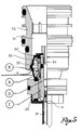
- FIG. 1 and 2 of the drawings 20 globally indicates a mixer valve body partially in cross section.
- the mixer valve body has, in the known manner, hot and cold water inlet ducts, which are arranged in the directions of the arrows AC and AF in Figure 1, and it is provided with a supply mouth 20' which is mounted downstream of a water outlet duct 21 which is defined by a coupling 22 attached to the valve body 20.
- a water outlet duct 21 which is defined by a coupling 22 attached to the valve body 20.
- the water inlet ducts only one appears in Figure 1 and is indicated as 23.
- the valve body 20 is also provided with a mixed water supply duct 24 to the outlet duct 21, a knob 25 for regulating the flow of water through the supply duct 24, an on/off housing 26 for a group of valves 27 which regulates the opening/closing of the water outlet duct 21, and an electronic housing 28 for the electronic component which controls the group of valves for opening/closing the valve.
- This electronic component is known per se and does not merit particular attention here. It should only be noted that the electronic component controls the group of valves 27 by means of a control electromagnet 29.
- the housing 26 for the group of valves 27 in the valve body 20 is placed axially to the water outlet duct 21, and the electromagnet 29 is placed axially below the group of valves.
- the group of valves 27 essentially consists of two components: a diaphragm valve 30 and a stop valve 31 with linear adjustments.
- the diaphragm valve 30 is made of an elastic material, such as rubber, and has essentially the shape of a partial sphere or of a small bowl, which can expand and contract radially, and it is placed flush with a valve seat 32 provided in the coupling 22 which defines the water outlet duct 21 towards the supply mouth.
- the diaphragm 30 is provided with a fixed internal element 33, which, in turn, is provided with a support coupling 34 which delimits an axial drain port D in line and in communication with the outlet duct 21.
- the duct D On its lower end, the duct D has an input port d which is closed and opened by the stop valve 31, whose adjustments in the closing and opening positions are controlled by the electromagnet 29, which is controlled by the electronic component of the valve 20.
- the diaphragm valve 30 has an intermediate annular component 30' above the small port A and is intended to rest with a slight pre-stress on the valve seat 32 when the diaphragm is expanded so as to close the passage of water from the supply duct 24 to the outlet duct 21.
- the diaphragm is contracted, its intermediate annular component 30' is moved away from the valve seat 32, thus opening the direct passage of water from the supply duct 24 to the outlet duct 21 for a normal supply.
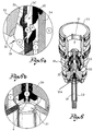
- the expansion and the contraction of the diaphragm results from the differences between the pressures on the inside and on the outside of the diaphragm, which are created with the opening and closing of the input port d of the drain port D by the stop valve 31.
- the diaphragm expands and begins to close when the internal pressure is greater than the external pressure (see Figure 8).
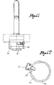
- the expansion of the diaphragm 30 can, moreover, be assisted by an elastic loading ring 36 arranged on the inside of the diaphragm itself at the level of its intermediate collar 30' as in Figure 9.
- the diaphragm 30, made of elastic material, that is, rubber, is designed to expand, close the valve seat 32 with a slight pre-stress and to block the water outlet duct 21.
- the small port A always puts the supply duct 24 in communication with the chamber 35 on the inside of the diaphragm, which also means that, thanks to the small port A, there is always a direct connection between the duct 24, the port B, and the outlet duct C.
- This pre-stress can be produced by the internal reaction that is characteristic of the material forming the diaphragm which is forced against the valve seat on mounting and is favored by the particular geometry of the diaphragm or, as stated above, accentuated by means of the use of an elastic ring as is shown in Figure 9.
- the entire unit would not function if the diameter of the beginning section of the port D were much smaller than the small port A. Load losses would be produced, which would lead to a high pressure on the inside of the diaphragm, and the operation of the diaphragm would become unstable. For this reason, the inlet port d of the axial port D is greater than the small radial port A of the diaphragm.
- the diaphragm is particularly suitable for applications in the field of valves in general and to achieve the purposes of reducing the sizes and to be able to also arrange the electronic component and the batteries inside the body and to give the valve the available, desired shapes.
- the stop valve 31 can be moved by an electromagnet as stated above or by a mechanical control drive.
- a second or another outlet port C' may also be provided (see Figure 10), this port comes from the chamber 35 of the diaphragm 30 and which opens towards the inlet port of the drain port D, with a stop valve 31' being inserted along the second outlet port C'.
- This stop valve rotates or traverses with manual control, and which, when operated, permits a manual opening/closing of the valve in cases of emergency, independently, that is, of the electromagnet and in the absence of the electric power supply.
- valve may be provided with an adjustable slider means 37 at a distance from and in front of the sensors 38 so as to make it possible to use the valve with automatic control (when the slider is at a distance from the sensors) or to leave the valve open for prolonged periods of time without the presence of anything in front of the sensors (when the slider is placed in front of the sensors so as to reflect the signals).
Landscapes
- Engineering & Computer Science (AREA)
- General Engineering & Computer Science (AREA)
- Mechanical Engineering (AREA)
- Magnetically Actuated Valves (AREA)
- Fluid-Driven Valves (AREA)
- Cosmetics (AREA)
- Multiple-Way Valves (AREA)
Claims (7)
- Vanne mélangeuse à commande électronique comprenant un corps (20) avec des conduites d'entrée de l'eau chaude et froide, une conduite de débit (24) de l'eau mélangée communiquant avec lesdites conduites d'entrée à travers des dispositifs de régulation de débit (25), une conduite de sortie de l'eau (21) communiquant avec la conduite de débit de l'eau mélangée (24) d'un côté et une bouche de distribution (20') de l'autre, la conduite de sortie (21) étant définie par un manchon (22) et la bouche de distribution étant appliquée sur ledit manchon, et un groupe de soupapes (27) qui régit l'ouverture et la fermeture de la conduite de sortie de l'eau (21) sous le contrôle d'un électro-aimant (29) géré par un composant électronique; elle est caractérisée par le fait que le groupe de soupapes (27) est placé à l'intérieur d'une enveloppe (26) dans le corps de la vanne qui est disposée axialement par rapport au manchon (22) qui définit la conduite de sortie de l'eau (21); ledit groupe de soupapes est formé par une soupape à diaphragme en matériau élastique, caoutchouc ou similaire, en forme essentiellement de barillet, qui s'étend axialement dans le manchon (22), située au niveau d'un siège de soupape (32) obtenu dans le manchon (22), et par un clapet contrôlé par ledit électro-aimant (29); ladite soupape à diaphragme (30) délimite une chambre intérieure (35) communiquant d'une part (A) avec la conduite (24) de débit de l'eau mélangée, et de l'autre (B), avec un orifice de sortie (C) qui s'étend dans la conduite de sortie (21) de l'eau vers la bouche de distribution à travers un orifice d'amenée (d) ouvert et fermé par le clapet (31) actionné par l'électro-aimant; la soupape à diaphragme (30) est en mesure de se détendre ou de se contracter radialement en fonction des différences de pression à l'intérieur et à l'extérieur de la chambre et du fait de l'ouverture/fermeture de l'orifice d'amenée (d) au moyen du clapet; à la fermeture dudit orifice d'amenée (d) pression à l'intérieur et à l'extérieur de la chambre et du fait de l'ouverture/fermeture de l'orifice d'amenée (d) au moyen du clapet; à la fermeture dudit orifice d'amenée (d) correspondent une expansion du diaphragme, la fermeture du siège de soupape (32) et l'interruption de l'écoulement d'eau vers la conduite de sortie et la bouche de distribution; à l'ouverture dudit orifice d'amenée (d) correspondent une contraction du diaphragme, l'ouverture du siège de soupape (32) et le passage de l'eau de la conduite de débit (24) à la conduite de sortie.
- Vanne mélangeuse conforme à la revendication 1, dans laquelle la soupape à diaphragme (30) présente un collier intermédiaire (30') en saillie destiné à s'appuyer radialement sur le siège de soupape (32) lorsque la soupape à diaphragme se détend, et à s'éloigner du siège de soupape lorsque la soupape à diaphragme se contracte, ladite soupape à diaphragme étant montée légèrement préchargée ou sous la précontrainte d'un anneau élastique (36) situé à l'intérieur au niveau du collier intermédiaire (30') et tendant à dilater le diaphragme.
- Vanne mélangeuse conforme aux revendications 1 et 2, dans laquelle la soupape à diaphragme (30) est supportée par un élément intérieur rigide (33) fixé sur un manchon coaxial de support (34) délimitant un orifice d'évacuation (D) parallèle à la conduite de sortie de l'eau (21) vers la bouche de distribution; ledit orifice d'évacuation (D) s'étend de l'orifice d'amenée (d), ouvert/fermé par le clapet (31); ladite soupape à diaphragme et ledit élément intérieur rigide délimitent une chambre (35) communiquant d'une part avec la conduite de débit (24) à travers un petit orifice radial de débit (A) pratiqué dans le diaphragme (30) et, d'autre part, avec l'orifice de sortie (C) à travers un orifice (B) pratiqué dans l'élément rigide; ledit orifice de sortie (C) s'étend sortie (C) à travers un orifice (B) pratiqué dans l'élément rigide; ledit orifice de sortie (C) s'étend dans le manchon de support (34), s'ouvre dans la direction de l'orifice d'amenée (d) et communique avec l'orifice d'évacuation (D) lorsque le clapet (31) est dans la position ouverte.
- Vanné mélangeuse conforme à la revendication 3, dans laquelle le petit orifice radial de débit (A) du diaphragme (30) a une section inférieure à celle de l'orifice d'amenée (d) contrôlé par le clapet (31).
- Vanne mélangeuse conforme à la revendication précédente, dans laquelle le corps de la vanne possède un logement pour les composants électronique et d'alimentation électrique régissant l'électro-aimant.
- Vanne mélangeuse conforme à toute revendication précédente, dans laquelle le manchon de support possède un deuxième orifice de sortie (C') le long duquel se trouve un clapet (31') à actionnement manuel pour établir la communication entre la chambre dans ledit diaphragme et l'orifice d'évacuation en cas d'urgence.
- Vanne mélangeuse conforme à toute revendication précédente, dans laquelle le corps de la vanne dispose d'un dispositif à coulisse (37) réglable loin ou face aux capteurs (38) contrôlant l'ouverture/fermeture électronique de la vanne.
Applications Claiming Priority (2)
| Application Number | Priority Date | Filing Date | Title |
|---|---|---|---|
| ITBS930024A IT1262712B (it) | 1993-03-18 | 1993-03-18 | Perfezionamenti ai rubinetti miscelatori a comando elettronico |
| ITBS930024 | 1993-03-23 |
Publications (2)
| Publication Number | Publication Date |
|---|---|
| EP0631078A1 EP0631078A1 (fr) | 1994-12-28 |
| EP0631078B1 true EP0631078B1 (fr) | 1997-10-15 |
Family
ID=11345031
Family Applications (1)
| Application Number | Title | Priority Date | Filing Date |
|---|---|---|---|
| EP94830126A Expired - Lifetime EP0631078B1 (fr) | 1993-03-18 | 1994-03-22 | Mitigeur avec un robinet à membrane |
Country Status (7)
| Country | Link |
|---|---|
| US (1) | US5524862A (fr) |
| EP (1) | EP0631078B1 (fr) |
| AT (1) | ATE159330T1 (fr) |
| CA (1) | CA2119679A1 (fr) |
| DE (1) | DE69406198T2 (fr) |
| ES (1) | ES2109651T3 (fr) |
| IT (1) | IT1262712B (fr) |
Families Citing this family (3)
| Publication number | Priority date | Publication date | Assignee | Title |
|---|---|---|---|---|
| CN1098432C (zh) * | 1998-03-06 | 2003-01-08 | 李南 | 小型可控截止阀 |
| GB2545473B (en) | 2015-12-17 | 2021-08-04 | Kohler Mira Ltd | Faucets |
| US12404948B2 (en) * | 2022-11-24 | 2025-09-02 | Hydrotek Corporation | Solenoid valve |
Family Cites Families (19)
| Publication number | Priority date | Publication date | Assignee | Title |
|---|---|---|---|---|
| US2336450A (en) * | 1941-01-16 | 1943-12-07 | Charles R Voorhess | Turbine regulator |
| US2608213A (en) * | 1947-07-02 | 1952-08-26 | Jr John O Hruby | Pilot controlled diaphragm-type valve |
| US3118646A (en) * | 1961-01-09 | 1964-01-21 | Dura Bond Bearing Company | Pilot operated valve |
| US3145967A (en) * | 1962-04-27 | 1964-08-25 | Lawrence H Gardner | Elastic sleeve valve |
| BE653013A (fr) * | 1963-12-13 | |||
| US3282556A (en) * | 1964-06-12 | 1966-11-01 | Hoffman Specialty Mfg Corp | Throttling button for diaphragm valve |
| US3685788A (en) * | 1970-05-15 | 1972-08-22 | Uniflo Systems Co | Valve for levitated vehicle track |
| US3854694A (en) * | 1970-10-01 | 1974-12-17 | M Coone | Apparatus for an aggregate pump |
| US3884261A (en) * | 1973-11-26 | 1975-05-20 | Frank Clynch | Remotely activated valve |
| NO139934C (no) * | 1976-07-22 | 1979-06-06 | Selvaag Ole Gunnar | Ventil for regulering av vaeskestroem. |
| GB1595240A (en) * | 1977-11-28 | 1981-08-12 | Kay F X | Fluid control valves |
| AU576806B2 (en) * | 1983-12-28 | 1988-09-08 | Sweepy International S.A. | Diaphragm valve assembly for pool cleaner |
| US4603832A (en) * | 1985-06-07 | 1986-08-05 | Evolutionary Concepts, Inc. | Solenoid actuator with bleed screw |
| EP0253064A3 (fr) * | 1986-07-08 | 1988-10-26 | AVS Ing. J.C. Römer GmbH | Soupape à diaphragme pour fluides |
| US4793588A (en) * | 1988-04-19 | 1988-12-27 | Coyne & Delany Co. | Flush valve with an electronic sensor and solenoid valve |
| US5050641A (en) * | 1990-05-08 | 1991-09-24 | Shwu Fen Sheu | Photoelectric single handle faucet |
| DE4102135C2 (de) * | 1991-01-25 | 1995-06-22 | Hansa Metallwerke Ag | Sanitäre Mischarmatur |
| DE4102134C2 (de) * | 1991-01-25 | 1995-09-07 | Hansa Metallwerke Ag | Berührungslos gesteuerte Sanitärarmatur |
| US5244179A (en) * | 1992-08-21 | 1993-09-14 | Sloan Valve Company | Diaphragm stop for sensor-operated, battery-powered flush valve |
-
1993
- 1993-03-18 IT ITBS930024A patent/IT1262712B/it active IP Right Grant
-
1994
- 1994-03-22 ES ES94830126T patent/ES2109651T3/es not_active Expired - Lifetime
- 1994-03-22 DE DE69406198T patent/DE69406198T2/de not_active Expired - Fee Related
- 1994-03-22 EP EP94830126A patent/EP0631078B1/fr not_active Expired - Lifetime
- 1994-03-22 US US08/215,907 patent/US5524862A/en not_active Expired - Fee Related
- 1994-03-22 AT AT94830126T patent/ATE159330T1/de not_active IP Right Cessation
- 1994-03-23 CA CA002119679A patent/CA2119679A1/fr not_active Abandoned
Also Published As
| Publication number | Publication date |
|---|---|
| CA2119679A1 (fr) | 1994-09-24 |
| ATE159330T1 (de) | 1997-11-15 |
| ITBS930024A0 (it) | 1993-03-18 |
| EP0631078A1 (fr) | 1994-12-28 |
| ITBS930024A1 (it) | 1994-09-18 |
| DE69406198D1 (de) | 1997-11-20 |
| IT1262712B (it) | 1996-07-04 |
| ES2109651T3 (es) | 1998-01-16 |
| DE69406198T2 (de) | 1998-04-02 |
| US5524862A (en) | 1996-06-11 |
Similar Documents
| Publication | Publication Date | Title |
|---|---|---|
| CA2364883A1 (fr) | Robinet de chasse comprenant un tube souple | |
| US6408881B2 (en) | Faucet device to deliver and mix water | |
| US5653260A (en) | Flow-rate limiting valve for inserting between a shower hose and a hand shower | |
| US4222410A (en) | Outlet fixture for fluid media | |
| EP0248079B1 (fr) | Robinet avec dispositif anti-siphon empechant le refoulement | |
| US4141383A (en) | Outlet fixture for fluid media | |
| US20230279960A1 (en) | Push-button tub and shower diverter | |
| EP0632220A2 (fr) | Boîte composée pour robinets d'eau | |
| US8555916B2 (en) | Solenoid valve having flow control function | |
| US4982459A (en) | Adjustable air and water entrainment hydrotherapy jet assembly | |
| CA2001734C (fr) | Interrupteur de sanitaire | |
| US4979539A (en) | Sanitary mixing valve | |
| EP0631078A1 (fr) | Mitigeur avec un robinet à membrane | |
| EP0466010B1 (fr) | Dispositif de soupape pour installation de chauffage | |
| CA2297867A1 (fr) | Corps de robinet avec emboitement de brise-vide integral | |
| US5220695A (en) | Adjustable air and water entrainment hydrotherapy jet assembly | |
| CN215806425U (zh) | 新型调流开关阀芯 | |
| JPH10338951A (ja) | 水栓装置 | |
| NZ500360A (en) | Automatic back water valve system with back-up of water causing actuation of bellows attached to valve lifting device | |
| CN109630715B (zh) | 龙头装置 | |
| EP1826323A2 (fr) | Dispositif d'écoulement et de trop-plein | |
| CA2373749A1 (fr) | Joint d'etancheite double de robinet de chasse | |
| US20200124184A1 (en) | System for opening and closing water for a shower head, hand shower or a bathroom or kitchen mixer | |
| CN215487928U (zh) | 一种带有检测开关的双水路电磁阀阀芯 | |
| BG63054B1 (bg) | Санитарен воден вентил |
Legal Events
| Date | Code | Title | Description |
|---|---|---|---|
| PUAI | Public reference made under article 153(3) epc to a published international application that has entered the european phase |
Free format text: ORIGINAL CODE: 0009012 |
|
| AK | Designated contracting states |
Kind code of ref document: A1 Designated state(s): AT BE DE ES FR GB GR IT NL PT |
|
| 17P | Request for examination filed |
Effective date: 19950617 |
|
| GRAG | Despatch of communication of intention to grant |
Free format text: ORIGINAL CODE: EPIDOS AGRA |
|
| GRAH | Despatch of communication of intention to grant a patent |
Free format text: ORIGINAL CODE: EPIDOS IGRA |
|
| 17Q | First examination report despatched |
Effective date: 19970312 |
|
| GRAH | Despatch of communication of intention to grant a patent |
Free format text: ORIGINAL CODE: EPIDOS IGRA |
|
| GRAA | (expected) grant |
Free format text: ORIGINAL CODE: 0009210 |
|
| AK | Designated contracting states |
Kind code of ref document: B1 Designated state(s): AT BE DE ES FR GB GR IT NL PT |
|
| PG25 | Lapsed in a contracting state [announced via postgrant information from national office to epo] |
Ref country code: NL Free format text: LAPSE BECAUSE OF FAILURE TO SUBMIT A TRANSLATION OF THE DESCRIPTION OR TO PAY THE FEE WITHIN THE PRESCRIBED TIME-LIMIT Effective date: 19971015 Ref country code: IT Free format text: LAPSE BECAUSE OF FAILURE TO SUBMIT A TRANSLATION OF THE DESCRIPTION OR TO PAY THE FEE WITHIN THE PRE;WARNING: LAPSES OF ITALIAN PATENTS WITH EFFECTIVE DATE BEFORE 2007 MAY HAVE OCCURRED AT ANY TIME BEFORE 2007. THE CORRECT EFFECTIVE DATE MAY BE DIFFERENT FROM THE ONE RECORDED.SCRIBED TIME-LIMIT Effective date: 19971015 Ref country code: GR Free format text: LAPSE BECAUSE OF FAILURE TO SUBMIT A TRANSLATION OF THE DESCRIPTION OR TO PAY THE FEE WITHIN THE PRESCRIBED TIME-LIMIT Effective date: 19971015 Ref country code: FR Free format text: LAPSE BECAUSE OF FAILURE TO SUBMIT A TRANSLATION OF THE DESCRIPTION OR TO PAY THE FEE WITHIN THE PRESCRIBED TIME-LIMIT Effective date: 19971015 Ref country code: BE Free format text: LAPSE BECAUSE OF FAILURE TO SUBMIT A TRANSLATION OF THE DESCRIPTION OR TO PAY THE FEE WITHIN THE PRESCRIBED TIME-LIMIT Effective date: 19971015 Ref country code: AT Free format text: LAPSE BECAUSE OF FAILURE TO SUBMIT A TRANSLATION OF THE DESCRIPTION OR TO PAY THE FEE WITHIN THE PRESCRIBED TIME-LIMIT Effective date: 19971015 |
|
| REF | Corresponds to: |
Ref document number: 159330 Country of ref document: AT Date of ref document: 19971115 Kind code of ref document: T |
|
| REF | Corresponds to: |
Ref document number: 69406198 Country of ref document: DE Date of ref document: 19971120 |
|
| PG25 | Lapsed in a contracting state [announced via postgrant information from national office to epo] |
Ref country code: PT Free format text: LAPSE BECAUSE OF FAILURE TO SUBMIT A TRANSLATION OF THE DESCRIPTION OR TO PAY THE FEE WITHIN THE PRESCRIBED TIME-LIMIT Effective date: 19980115 |
|
| REG | Reference to a national code |
Ref country code: ES Ref legal event code: FG2A Ref document number: 2109651 Country of ref document: ES Kind code of ref document: T3 |
|
| NLV1 | Nl: lapsed or annulled due to failure to fulfill the requirements of art. 29p and 29m of the patents act | ||
| EN | Fr: translation not filed | ||
| PG25 | Lapsed in a contracting state [announced via postgrant information from national office to epo] |
Ref country code: GB Free format text: LAPSE BECAUSE OF NON-PAYMENT OF DUE FEES Effective date: 19980322 |
|
| PG25 | Lapsed in a contracting state [announced via postgrant information from national office to epo] |
Ref country code: ES Free format text: LAPSE BECAUSE OF NON-PAYMENT OF DUE FEES Effective date: 19980323 |
|
| PLBE | No opposition filed within time limit |
Free format text: ORIGINAL CODE: 0009261 |
|
| STAA | Information on the status of an ep patent application or granted ep patent |
Free format text: STATUS: NO OPPOSITION FILED WITHIN TIME LIMIT |
|
| 26N | No opposition filed | ||
| GBPC | Gb: european patent ceased through non-payment of renewal fee |
Effective date: 19980322 |
|
| PG25 | Lapsed in a contracting state [announced via postgrant information from national office to epo] |
Ref country code: DE Free format text: LAPSE BECAUSE OF NON-PAYMENT OF DUE FEES Effective date: 19981201 |
|
| REG | Reference to a national code |
Ref country code: ES Ref legal event code: FD2A Effective date: 19990414 |