EP0631082A1 - Verbindung zwischen zwei Rohren - Google Patents
Verbindung zwischen zwei Rohren Download PDFInfo
- Publication number
- EP0631082A1 EP0631082A1 EP94107222A EP94107222A EP0631082A1 EP 0631082 A1 EP0631082 A1 EP 0631082A1 EP 94107222 A EP94107222 A EP 94107222A EP 94107222 A EP94107222 A EP 94107222A EP 0631082 A1 EP0631082 A1 EP 0631082A1
- Authority
- EP
- European Patent Office
- Prior art keywords
- pipe
- connection
- stop
- tube
- wall
- Prior art date
- Legal status (The legal status is an assumption and is not a legal conclusion. Google has not performed a legal analysis and makes no representation as to the accuracy of the status listed.)
- Granted
Links
- 239000000463 material Substances 0.000 claims abstract description 9
- 238000007493 shaping process Methods 0.000 claims abstract description 6
- 238000003780 insertion Methods 0.000 claims description 17
- 230000037431 insertion Effects 0.000 claims description 17
- 238000013508 migration Methods 0.000 claims description 2
- 230000005012 migration Effects 0.000 claims description 2
- 238000006073 displacement reaction Methods 0.000 abstract 1
- 239000003507 refrigerant Substances 0.000 description 8
- 239000007788 liquid Substances 0.000 description 3
- 239000000853 adhesive Substances 0.000 description 2
- 230000001070 adhesive effect Effects 0.000 description 2
- 239000011324 bead Substances 0.000 description 2
- 238000004519 manufacturing process Methods 0.000 description 2
- 238000000034 method Methods 0.000 description 2
- 238000005057 refrigeration Methods 0.000 description 2
- 229910000679 solder Inorganic materials 0.000 description 2
- 239000011230 binding agent Substances 0.000 description 1
- 230000006835 compression Effects 0.000 description 1
- 238000007906 compression Methods 0.000 description 1
- 238000002788 crimping Methods 0.000 description 1
- 238000005520 cutting process Methods 0.000 description 1
- 230000000694 effects Effects 0.000 description 1
- 230000000717 retained effect Effects 0.000 description 1
Images
Classifications
-
- F—MECHANICAL ENGINEERING; LIGHTING; HEATING; WEAPONS; BLASTING
- F16—ENGINEERING ELEMENTS AND UNITS; GENERAL MEASURES FOR PRODUCING AND MAINTAINING EFFECTIVE FUNCTIONING OF MACHINES OR INSTALLATIONS; THERMAL INSULATION IN GENERAL
- F16L—PIPES; JOINTS OR FITTINGS FOR PIPES; SUPPORTS FOR PIPES, CABLES OR PROTECTIVE TUBING; MEANS FOR THERMAL INSULATION IN GENERAL
- F16L25/00—Construction or details of pipe joints not provided for in, or of interest apart from, groups F16L13/00 - F16L23/00
- F16L25/10—Sleeveless joints between two pipes, one being introduced into the other
Definitions
- the invention relates to a connection between two tubes which are inserted into one another and connected to one another for the purpose of their connection, the insertion depth of one tube into the other being limited by a stop arranged on the inserted tube.
- Such pipe connections are also used, for example, in evaporators of refrigerators and freezers when it comes to connecting the capillary tube used to relax the liquid refrigerant to the channel system of an evaporator, the former for the purpose of its connection over a certain length in the channel system due to its external dimensions of the evaporator is introduced. It is important to ensure that the free, inserted end is not chosen too long, since otherwise the refrigerant exiting the capillary tube with high energy causes this end to vibrate in such a way that it contacts the channel walls of the channel section from which it is received. strikes and thus forms an almost constantly working source of noise.
- a too short insertion depth could result in that a binding effecting the connection between the capillary tube and the channel system of the evaporator, such as, for example, liquid adhesive or solder, could at least partially block the tube cross section of the capillary tube as a result of flow generated by capillary forces.
- a pipe connection between an evaporator suction pipe and a connection channel arranged on the evaporator board is known, the pipe connection between the connection channel of the evaporator and the evaporator suction pipe being established in that the latter is inserted into the connection channel .
- the latter is provided with a bead protruding from its outer circumference, which serves as a stop when the evaporator suction pipe is inserted into the end channel.
- the invention has for its object to design the stop for limiting the insertion depth in a pipe connection according to the preamble of claim 1 so that the disadvantages of the prior art are avoided in a simple manner.
- the object is achieved according to the invention in that the stop at least from a partial, plastic shape on the outer circumference of the tube wall of the inserted tube by an exclusive material migration of the deformed Wall material is generated to the outer circumference of the pipe bevel.
- the solution according to the invention ensures above all that the flow cross-section originally present is retained even after the stop has been formed, so that when the pipe flows through, e.g. unpleasant noises are avoided with high-speed liquid refrigerants. Furthermore, this solution is characterized by the fact that the simple generation of the stop creates an inexpensive insertion depth limitation, as a result of which a reproducible and controllable insertion depth is achieved.
- the inserted tube is supported in the region of its deformation points which serve to produce the stop by the cross-sectional shape and the cross-sectional area of the inside diameter of the inserted tube which essentially maintains it.
- the plastic shape forming the stop can be made particularly stable and manufactured with high accuracy if, according to a further advantageous embodiment of the object of the invention, it is provided that the plastic shape forming the stop is formed by partially squeezing the outer circumference of the tube wall.
- the plastic shape forming the stop is formed by chip shaping of the outer circumference of the tube wall.
- two stops are produced by plastic shaping, which enclose an angle of 180 ° between them.
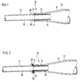
- FIG. 1 shows a pipe connection 10 which is used in a refrigeration device (not shown) and which is formed from two pipe sections 11 and 12 joined together at the connection point by plugging one into the other, of which the pipe section designated 11 serves as the condenser of the refrigeration device and serves as a throttle element Capillary tube formed and inserted into the other tube section 12, which serves as a dryer cartridge.
- the latter has a cylindrical part 13 and an adjoining, conically widening part 14, the cylindrical part 13 serving to receive a pipe stub 15 of the pipe section 11 being approximately identical in terms of its inner diameter to achieve certain guiding properties at the joint on the outer diameter of the pipe stub 15 is coordinated.
- the guide air is designed so that a capillary gap can form over the circumference of the two cooperating diameters of the pipe stub 15 and the cylindrical part 13, into which the binding agent of solder or adhesive which causes the connection at the joint is sucked capillary.
- a pipe segment 11 which is inserted and provided with the pipe stub 15 has a circular segment-like shape which limits its insertion depth into the pipe section 12 and encloses an angle of 180 ° between them
- the stops 16 on the inserted pipe section 11 are formed from partial plastic deformations of the wall material arranged on the outer circumference of its pipe wall 18, essentially in the vicinity of the outer circumference and perpendicular to the axis of the pipe section 11 by crimping with subsequent compression of the wall material.
- the areas of the pipe section 11 which are subjected to a plastic deformation in order to produce them can be supported with support means (not shown) in the form of auxiliary tools. The latter are introduced before each deformation process and over its duration in order to generate the support in the free pipe passage determined by the inner diameter of the pipe section 11 and have the cross-sectional shape and the cross-sectional area of the inner diameter of the inserted pipe section 11.
- FIG 2 a further embodiment of the insertion depth of the pipe section 11 into the pipe section 12 stops 20 is shown, which are generated by chip deformation in the axial direction of the pipe section 11 over a length which makes up the length of the pipe stub 15, the length of which on the end face of the cylindrical part 13 of the pipe section 12 abutting abutment surfaces 21 lie in the area of the chip root for reasons of stability and face the inserted pipe stub 15 of the pipe section 11.
- a cutting tool is guided along the axis of the pipe section 11 at a corresponding depth in the wall thickness material of the pipe wall 18. in order to produce dimensionally stable stops 20 by the removed chip.
Landscapes
- Engineering & Computer Science (AREA)
- General Engineering & Computer Science (AREA)
- Mechanical Engineering (AREA)
- Non-Disconnectible Joints And Screw-Threaded Joints (AREA)
- Supports For Pipes And Cables (AREA)
- Ink Jet (AREA)
Abstract
Description
- Die Erfindung betrifft eine Verbindung zwischen zwei Rohren, die zum Zweck ihrer Verbindung ineinandergesteckt und miteinander verbunden sind, wobei die Einstecktiefe des einen Rohres in das andere durch einen am eingesteckten Rohr angeordneten Anschlag begrenzt ist.
- Derartige Rohrverbindungen finden beispielsweise auch bei Verdampfern von Kühl- und Gefriergeräten Anwendung, wenn es darum geht, daß zur Entspannung des flüssigen Kältemittels dienende Kapillarrohr an das Kanalsystem eines Verdampfers anzuschließen, wobei ersteres zum Zwecke seines Anschlusses aufgrund seiner Außenabmessungen über eine bestimmte Länge in das Kanalsystem des Verdampfers eingeführt wird. Dabei gilt es zu beachten, daß das freie, eingeschobene Ende nicht zu lang gewählt wird, da sonst das mit hoher Energie aus dem Kapillarrohr austretende Kältemittel dieses Ende derart in Schwingungen versetzt, daß es an den Kanalwandungen des Kanalabschnittes, von dem es aufgenommen ist, anschlägt und somit eine nahezu ständig arbeitende Geräuschquelle bildet. Eine zu kurz gewählte Einstecktiefe hätte u.U. zur Folge, daß ein die Verbindung zwischen dem Kapillarrohr und dem Kanalsystem des Verdampfers bewirkendes Bindemittel, wie beispielsweise flüssiger Kleber oder Lot, infolge von Kapillarkräften erzeugten Fluß den Rohrquerschnitt des Kapillarrohrs zumindest teilweise zusetzen könnte.
- Um dies zu vermeiden, ist man dazu übergegangen, die Einstecklänge des Kapillarrohrs in den Kältemittelkanal auf ein definiertes Maß zu begrenzen, um sicher zu stellen, daß einerseits die das Geräusch verursachenden Auslenkungen des Kapillarrohrs aufgrund des austretenden Kältemittelstroms durch die Aufnahmestelle des Kapillarrohrs im Kältemittelkanal aufgefangen werden und andererseits die Möglichkeit des Zusetzens des Kapillarrohrs nicht gegeben ist.
- Als die Einstecktiefe des Kapillarrohrs begrenzende Maßnahme wurde hierzu bereits vorgeschlagen, dieses mit einer Abkröpfung auszustatten, daß die eingesteckte Länge des Kapillarrohrs in den Kältemittelkanal stets die gleiche ist. Problematisch bei dieser Art von Einstecktiefen-Begrenzung ist allerdings, daß durch die Abkröpfung der innere Rohrquerschnitt des Kapillarrohrs verengt wird, wodurch sich die Geschwindigkeit des Kältemittelstromes an dieser Stelle erhöht. Dies hat zur Folge, daß oftmals deutlich hörbare, unangenehme Strömungsgeräusche entstehen.
- Eine weitere Einstecktiefen-Begrenzung für ein in eine Führungsröhre eingestecktes Kapillarrohr ist aus dem DE-GM 89 05 478 bekannt. Darin wird vorgeschlagen, daß Führungsrohr entlang seines Umfangs mit einer beispielsweise als Sicke ausgeführten Einprägung zu versehen, wodurch das Material der Rohrwandung einen Anschlag für das eingesteckte Kapillarrohr bildend, in den freien Querschnitt des Innendurchmessers des Führungsrohres gedrängt ist.
- Weiterhin ist aus der DE-AS 12 42 646 eine Rohrverbindung zwischen einem Verdampfer-Saugrohr und einem an der Verdampferplatine angeordneten Anschlußkanal bekannt, wobei die Rohrverbindung zwischen dem Anschlußkanal des Verdampfers und dem Verdampfer-Saugrohr dadurch hergestellt ist, daß letzeres in den Anschlußkanal eingesteckt ist. zur Begrenzung der Einstecktiefe des Verdampfer-Saugrohrs ist dieses mit einem gegenüber seinem äußeren Umfang vorstehenden Wulst versehen, der als Anschlag beim Einstecken des Verdampfer-Saugrohrs in den Abschlußkanal dient.
- All diesen Lösungsvorschlägen ist gemeinsam, daß der die Einstecktiefe der beiden Rohre ineinander begrenzende Anschlag durch eine den freien Durchflußquerschnitt verändernde Rohrwandverformung eine der beiden miteinander zu verbindenden Rohre bewerkstelligt ist. Eine derartige Verformung wirkt sich zumindest, infolge der sich plötzlich ändernden Strömungsgeschwindigkeit an dieser Stelle, geräuschfördernd aus.
- Der Erfindung liegt die Aufgabe zugrunde, bei einer Rohrverbindung gemäß dem Oberbegriff des Anspruches 1 den Anschlag zur Begrenzung der Einstecktiefe so zu gestalten, daß auf einfache Weise die Nachteile des Standes der Technik vermieden sind.
- Die Aufgabe wird gemäß der Erfindung dadurch gelöst, daß der Anschlag zumindest aus einer partiellen, plastischen Formgebung am äußeren Umfang der Rohrwandung des eingesteckten Rohres durch eine ausschließliche Materialwanderung des verformten Wandmaterials zum äußeren Umfang der Rohrwahndung hin erzeugt ist.
- Durch die erfindungsgemäße Lösung ist vor allem sichergestellt, daß der ursprünglich vorhandene Durchflußquerschnitt auch nach Anformung des Anschlags erhalten ist, so daß bei Durchströmung des Rohres, z.B. mit flüssigen Kältemittel hoher Geschwindigkeit unangenehme Geräuschentwicklungen vermieden sind. Des weiteren zeichnet sich diese Lösung noch dadurch aus, daß durch die einfache Erzeugung des Anschlags eine kostengünstige Stecktiefenbegrenzung geschaffen ist, wodurch eine reproduzierbare und auch kontrollierbare Einstecktiefe erreicht ist.
- Nach einer weiteren, bevorzugten Ausführungsform des Gegenstandes der Erfindung ist vorgesehen, daß das eingesteckte Rohr im Bereich seiner zur Erzeugung des Anschlags dienenden Verformungsstellen von die Querschnittsform und die Querschnittsfläche des Innendurchmessers des eingesteckten Rohres im wesentlichen erhaltenden Stützmitteln abgestützt ist.
- Diese Lösung zeichnet sich dadurch aus, daß der Verformungsvorgang aufgrund der deutlich geringeren Anforderung an die Positioniergenauigkeit der Verformungswerkzeuge wesentlich rascher und somit kostengünstiger ausgeführt werden kann.
- Besonders stabil ausgeführt und mit hoher Genauigkeit hergestellt werden kann die den Anschlag bildende plastische Formgebung, wenn nach einer weiteren vorteilhaften Ausgestaltung des Gegenstandes der Erfindung vorgesehen ist, daß die den Anschlag bildende plastische Formgebung durch partielles Anquetschen des äußeren Umfangs der Rohrwandung gebildet ist.
- Gemäß einer nächsten vorteilhaften Ausgestaltung des Gegenstandes der Erfindung ist vorgesehen, daß die den Anschlag bildende plastische Formgebung durch Spanverformen des äußeren Umfangs der Rohrwandung gebildet ist.
- Diese Lösung zeichnet sich vor allem durch ihre äußerst preisgünstige Herstellung aus.
- Nach einer weiteren bevorzugten Ausführungsform des Gegenstandes der Erfindung ist vorgesehen, daß zwei durch plastische Formgebung erzeugte Anschläge vorgesehen sind, die einen Winkel von 180° zwischen sich einschließen.
- Der Vorteil einer derartigen Lösung ist darin zu sehen, daß auf bei nicht exakter Anpassung des Außendurchmessers des eingesteckten Rohres auf den Innendurchmesser des das Ein-stecken erlaubenden Rohres eine parallele Ausrichtung der Rohrachsen mit relativ hoher Genauigkeit gewährleistet ist.
- Die Erfindung ist in der nachfolgenden Beschreibung anhand von zwei in der Zeichnung vereinfacht dargestellten Ausführungsbeispielen erläutert. Es zeigen:
- Fig. 1
- in einem ersten Ausführungsbeispiel ausschnittsweise eine teilweise in Schnittansicht dargestellte Rohrverbindung, deren einzelne Rohrabschnitte an der Verbindungsstelle ineinandergesteckt sind, wobei die Einstecktiefe durch Anschläge an der Rohrwandung des eingesteckten Abschnitts begrenzt ist, in vergrößertem Maßstab und
- Fig. 2
- in einem zweiten Ausführungsbeispiel eine Rohrverbindung ähnlich der in Fig. 1 dargestellten, bei der jedoch die Einstecktiefe des eingesteckten Rohrabschnitts begrenzenden Anschläge auf andere Art erzeugt sind.
- Gemäß Fig. 1 ist eine bei einem nicht gezeigten Kältegerät in Anwendung kommende Rohrverbindung 10 dargestellt, die aus zwei an der Verbindungsstelle durch Ineinanderstecken zusammengefügte Rohrabschnitte 11 und 12 gebildet ist von denen der mit 11 bezeichnete Rohrabschnitt als den Verflüssiger des Kältegeräts nachgeschaltetes, als Drosselorgan dienendes Kapillarrohr ausgebildet und in den anderen Rohrabschnitt 12, der als Trocknerpatrone dient, eingesteckt ist. Letztere weist eine zylindrischen Teil 13 und einen daran anschließenden, sich kegelartig erweiternden Teil 14 auf, wobei der zylinderische, zur Aufnahme eines Rohrstummels 15 des Rohrabschnitts 11 dienende Teil 13 hinsichtlich seines Innendurchmessers zur Erzielung gewisser Führungseigenschaften an der Fügestelle auf den Außendurchmesser des Rohrstummels 15 annähernd abgestimmt ist. Die Führungsluft ist dabei so ausgelegt, daß sich über den Umfang der beiden zusammenwirkenden Durchmesser der Rohrstummel 15 und des zylindrischen Teils 13 ein Kapillarspalt ausbilden kann, in den sich das die Verbindung an der Fügestelle bewirkende Bindemittel von Lötzinn oder Klebstoff kapillarisch saugt.
- Um die Überlappung des Rohrstummels 15 und des zylindrischen Teils 13 an der Fügestelle auf ein gewisses Maß zu begrenzen, sind am eingesteckten, mit dem Rohrstummel 15 versehenen Rohrabschnitt 11 ein dessen Einstecktiefe in den Rohrabschnitt 12 begrenzende, einen Winkel von 180° zwischen sich einschließende kreissegmentartige Anschläge 16 angeordnet, deren Anschlagflächen 17 durch die dem eingesteckten Rohrstummel 15 des Rohrabschnittes 11 zugewandten Abschnitte der Kreissegmente gebildet sind und mit der ihnen zugewandten Stirnfläche des zylindrischen Teils 13 zusammenwirken. Die Anschläge 16 am eingesteckten Rohrabschnitt 11 sind aus am äußeren Umfang seiner Rohrwandung 18 angeordneten partiellen plastischen Verformungen des Wandmaterials im wesentlichen im Nahbereich des äußeren Umfangs und senkrecht zur Achse des Rohrabschnitts 11 durch Anquetschen mit anschließendem Verdichten des Wandungsmaterials gebildet. Aus Gründen einer beschleunigten Herstellung der Anschläge 16 können die zu ihrer Erzeugung einer plastischen Verformung unterzogenen Bereiche des Rohrabschnitts 11 mit in Form von Hilfswerkzeugen ausgebildeten, nicht dargestellten Stützmitteln abgestützt werden. Letztere werden vor jedem Verformungsvorgang und über dessen Dauer hinweg, zur Erzeugung der Abstützung in den durch den Innendurchmesser des Rohrabschnitts 11 bestimmten freien Rohrdurchlaß eingebracht und weisen die Querschnittform und die Querschnittsfläche des Innendurchmessers des eingesteckten Rohrabschnitts 11 auf.
- In Figur 2 ist eine weitere Ausführungsform von die Einstecktiefe des Rohrabschnitts 11 in den Rohrabschnitt 12 begrenzenden Anschlägen 20 dargestellt, welche durch Spanverformen in Achsrichtung des Rohrabschnitts 11 über eine die Länge des Rohrstummels 15 ausmachende Länge erzeugt werden, wobei deren an der Stirnseite des zylindrischen Teils 13 des Rohrabschnitts 12 anschlagenden Anschlagsflächen 21 aus Stabilitätsgründen im Bereich der Spanwurzel liegen und dem eingesteckten Rohrstummel 15 des Rohrabschnitts 11 zugekehrt sind. Zur Erzeugung der Anschläge 20 wird ein Schneidwerkzeug entlang der Achse des Rohrabschnitts 11 in entsprechender Tiefe des Wandstärkenmaterials der Rohrwandung 18 geführt, um durch den abgetragenen Span formstabile Anschläge 20 zu erzeugen.
Claims (5)
- Verbindung zwischen zwei Rohren, die zum Zweck ihrer Verbindung ineinandergesteckt und miteinander verbunden sind, wobei die Einstecktiefe des einen Rohrs in das andere durch einen am eingesteckten Rohr angeordneten Anschlag begrenzt ist, dadurch gekennzeichnet , daß der Anschlag (16, 20) zumindest aus einer partiellen plastischen Formgebung am äußeren Umfang der Rohrwandung des eingesteckten Rohres (11) durch eine ausschließliche Materialwanderung des verformten Wandmaterials zum äußeren Umfang der Rohrwandung (18) hin erzeugt ist.
- Verbindung zwischen zwei Rohren, dadurch gekennzeichnet, daß das eingesteckte Rohr (11) im Bereich seiner zur Erzeugung des Anschlags (16, 20) dienenden Verformungsstellen von die Querschnittsform und die Querschnittsfläche des Innendurchmessers des eingesteckten Rohres (11) im wesentlichen erhaltenden Stützmitteln abgestützt ist.
- Verbindung zwischen zwei Rohren nach Anspruch 1 oder 2, dadurch gekennzeichnet, daß die den Anschlag (16) bildende plastische Formgebung durch partielles Anquetschen des äußeren Umfangs der Rohrwandung (18) gebildet ist.
- Verbindung zwischen zwei Rohren nach Anspruch 1 oder 2, dadurch gekennzeichnet, daß die den Anschlag (20) bildende plastische Formgebung durch Spanverformen des äußeren Umfangs der Rohrwandung (18) gebildet ist.
- Verbindung nach einem der Ansprüche 1 bis 4, dadurch gekennzeichnet, daß zwei durch plastische Formgebung erzeugte Anschläge (16, 20) vorgesehen sind, die einen Winkel von 180° zwischen sich einschließen.
Applications Claiming Priority (2)
| Application Number | Priority Date | Filing Date | Title |
|---|---|---|---|
| DE19934321072 DE4321072A1 (de) | 1993-06-24 | 1993-06-24 | Verbindung zwischen zwei Rohren |
| DE4321072 | 1993-06-24 |
Publications (2)
| Publication Number | Publication Date |
|---|---|
| EP0631082A1 true EP0631082A1 (de) | 1994-12-28 |
| EP0631082B1 EP0631082B1 (de) | 1998-08-12 |
Family
ID=6491172
Family Applications (1)
| Application Number | Title | Priority Date | Filing Date |
|---|---|---|---|
| EP19940107222 Expired - Lifetime EP0631082B1 (de) | 1993-06-24 | 1994-05-09 | Verbindung zwischen zwei Rohren |
Country Status (4)
| Country | Link |
|---|---|
| EP (1) | EP0631082B1 (de) |
| DE (2) | DE4321072A1 (de) |
| DK (1) | DK0631082T3 (de) |
| ES (1) | ES2122080T3 (de) |
Cited By (2)
| Publication number | Priority date | Publication date | Assignee | Title |
|---|---|---|---|---|
| EP1030134A3 (de) * | 1999-02-19 | 2002-07-10 | BSH Bosch und Siemens Hausgeräte GmbH | Verdampferplatine |
| CN106288527A (zh) * | 2016-09-24 | 2017-01-04 | 海信(山东)空调有限公司 | 一种空调换热器组件及其装配方法 |
Families Citing this family (1)
| Publication number | Priority date | Publication date | Assignee | Title |
|---|---|---|---|---|
| DE4436777A1 (de) * | 1994-10-14 | 1996-04-25 | Wielage Bernhard Dr | Gasdichte Verbindungen zwischen Rohren mit kleinen Durchmessern |
Citations (3)
| Publication number | Priority date | Publication date | Assignee | Title |
|---|---|---|---|---|
| DE1242646B (de) * | 1961-02-08 | 1967-06-22 | Schmoele Metall R & G | Kaelteeinrichtung fuer Kuehlschraenke |
| GB1512961A (en) * | 1974-12-04 | 1978-06-01 | Wakelin R | Tube couplings |
| US4135740A (en) * | 1976-09-27 | 1979-01-23 | Carrier Corporation | Oval bell concept |
-
1993
- 1993-06-24 DE DE19934321072 patent/DE4321072A1/de not_active Withdrawn
-
1994
- 1994-05-09 DE DE59406648T patent/DE59406648D1/de not_active Expired - Lifetime
- 1994-05-09 EP EP19940107222 patent/EP0631082B1/de not_active Expired - Lifetime
- 1994-05-09 DK DK94107222T patent/DK0631082T3/da active
- 1994-05-09 ES ES94107222T patent/ES2122080T3/es not_active Expired - Lifetime
Patent Citations (3)
| Publication number | Priority date | Publication date | Assignee | Title |
|---|---|---|---|---|
| DE1242646B (de) * | 1961-02-08 | 1967-06-22 | Schmoele Metall R & G | Kaelteeinrichtung fuer Kuehlschraenke |
| GB1512961A (en) * | 1974-12-04 | 1978-06-01 | Wakelin R | Tube couplings |
| US4135740A (en) * | 1976-09-27 | 1979-01-23 | Carrier Corporation | Oval bell concept |
Cited By (3)
| Publication number | Priority date | Publication date | Assignee | Title |
|---|---|---|---|---|
| EP1030134A3 (de) * | 1999-02-19 | 2002-07-10 | BSH Bosch und Siemens Hausgeräte GmbH | Verdampferplatine |
| CN106288527A (zh) * | 2016-09-24 | 2017-01-04 | 海信(山东)空调有限公司 | 一种空调换热器组件及其装配方法 |
| CN106288527B (zh) * | 2016-09-24 | 2018-01-30 | 海信(山东)空调有限公司 | 一种空调换热器组件及其装配方法 |
Also Published As
| Publication number | Publication date |
|---|---|
| EP0631082B1 (de) | 1998-08-12 |
| DE59406648D1 (de) | 1998-09-17 |
| ES2122080T3 (es) | 1998-12-16 |
| DK0631082T3 (da) | 1999-05-17 |
| DE4321072A1 (de) | 1995-01-05 |
Similar Documents
| Publication | Publication Date | Title |
|---|---|---|
| DE2531857A1 (de) | Kupplung fuer optische lichtleitfasern | |
| EP0566899A1 (de) | Wärmetauscher, insbesondere Verdampfer | |
| EP0629824A1 (de) | Verdampfer für ein Kompressor-Kühlgerät | |
| DE2113581C2 (de) | Flachrohr und Verfahren zum Herstellen desselben | |
| DE4106574A1 (de) | Molekularstrahlseparator | |
| DE2257822B2 (de) | Verfahren zur Herstellung eines Wellenleiters | |
| WO2000034706A1 (de) | Vorrichtung zur herstellung einer rohrkupplung | |
| EP0631082B1 (de) | Verbindung zwischen zwei Rohren | |
| DE3902046A1 (de) | Waermeaustauscher mit zustandsaenderung eines mediums, wie z.b. ein verdampfer, fuer eine klimaanlage, insbesondere fuer ein kraftfahrzeug | |
| EP1492991B1 (de) | Gelöteter wärmeübertrager | |
| DE9015090U1 (de) | Sammler für einen Flachrohrverflüssiger | |
| EP0114947A2 (de) | Schreibgerät für flüssige Schreibmedien | |
| DE102017109065B4 (de) | Verbindungssystem zur gas- und fluiddichten Verbindung eines Verflüssigers einer Wärmepumpe mit einem Verdampfer der Wärmepumpe | |
| DE3420652C2 (de) | ||
| DE2302158A1 (de) | Verfahren zur herstellung einer sekundaeremissionskanalplatte mit gebogenen kanaelen | |
| DE2436248A1 (de) | Verdampferplatine, insbesondere walzgeschweisste verdampferplatine | |
| EP1293743B1 (de) | Wärmeübertrager-Flachrohrblock mit umgeformten Flachrohrenden | |
| DE102012003913A1 (de) | Kühl- und/oder Gefriergerät | |
| EP0461308A1 (de) | Übergangsstück zum Verbinden von Kunststoffrohren mit Armaturen aus metallischen Werkstoffen, insbesondere im Sanitär- und Heizungsbereich | |
| DE3136374A1 (de) | Verdampfer, insbesondere fuer klimaanlagen in kraftfahrzeugen | |
| AT286725B (de) | Lösbare Muffenrohrverbindung für plastisch verformbare Rohre, insbesondere thermoplastische Kunststoffrohre | |
| DE2156239B2 (de) | Konvektor mit einer Anzahl von parallelen, im wesentlichen ebenen Blechflanschen | |
| DE2758134C2 (de) | Verfahren zur Herstellung von Wärmetauscherrohre!) mit inneren und äußeren Längsrippen | |
| EP0086860A1 (de) | Anordnung zur Verbindung zweier Rohrenden | |
| EP1887304B1 (de) | Wärmeübertrager, insbesondere für Kraftfahrzeuge |
Legal Events
| Date | Code | Title | Description |
|---|---|---|---|
| PUAI | Public reference made under article 153(3) epc to a published international application that has entered the european phase |
Free format text: ORIGINAL CODE: 0009012 |
|
| AK | Designated contracting states |
Kind code of ref document: A1 Designated state(s): DE DK ES FR GB IT SE |
|
| 17P | Request for examination filed |
Effective date: 19950627 |
|
| 17Q | First examination report despatched |
Effective date: 19961007 |
|
| GRAG | Despatch of communication of intention to grant |
Free format text: ORIGINAL CODE: EPIDOS AGRA |
|
| GRAG | Despatch of communication of intention to grant |
Free format text: ORIGINAL CODE: EPIDOS AGRA |
|
| GRAH | Despatch of communication of intention to grant a patent |
Free format text: ORIGINAL CODE: EPIDOS IGRA |
|
| GRAH | Despatch of communication of intention to grant a patent |
Free format text: ORIGINAL CODE: EPIDOS IGRA |
|
| GRAA | (expected) grant |
Free format text: ORIGINAL CODE: 0009210 |
|
| RAP1 | Party data changed (applicant data changed or rights of an application transferred) |
Owner name: BSH BOSCH UND SIEMENS HAUSGERAETE GMBH |
|
| AK | Designated contracting states |
Kind code of ref document: B1 Designated state(s): DE DK ES FR GB IT SE |
|
| GBT | Gb: translation of ep patent filed (gb section 77(6)(a)/1977) |
Effective date: 19980814 |
|
| REF | Corresponds to: |
Ref document number: 59406648 Country of ref document: DE Date of ref document: 19980917 |
|
| ET | Fr: translation filed | ||
| REG | Reference to a national code |
Ref country code: ES Ref legal event code: FG2A Ref document number: 2122080 Country of ref document: ES Kind code of ref document: T3 |
|
| REG | Reference to a national code |
Ref country code: DK Ref legal event code: T3 |
|
| PLBE | No opposition filed within time limit |
Free format text: ORIGINAL CODE: 0009261 |
|
| STAA | Information on the status of an ep patent application or granted ep patent |
Free format text: STATUS: NO OPPOSITION FILED WITHIN TIME LIMIT |
|
| 26N | No opposition filed | ||
| REG | Reference to a national code |
Ref country code: GB Ref legal event code: IF02 |
|
| PGFP | Annual fee paid to national office [announced via postgrant information from national office to epo] |
Ref country code: SE Payment date: 20040524 Year of fee payment: 11 |
|
| PGFP | Annual fee paid to national office [announced via postgrant information from national office to epo] |
Ref country code: DK Payment date: 20040526 Year of fee payment: 11 |
|
| PG25 | Lapsed in a contracting state [announced via postgrant information from national office to epo] |
Ref country code: SE Free format text: LAPSE BECAUSE OF NON-PAYMENT OF DUE FEES Effective date: 20050510 |
|
| PG25 | Lapsed in a contracting state [announced via postgrant information from national office to epo] |
Ref country code: DK Free format text: LAPSE BECAUSE OF NON-PAYMENT OF DUE FEES Effective date: 20050531 |
|
| EUG | Se: european patent has lapsed | ||
| REG | Reference to a national code |
Ref country code: DK Ref legal event code: EBP |
|
| PGFP | Annual fee paid to national office [announced via postgrant information from national office to epo] |
Ref country code: FR Payment date: 20110603 Year of fee payment: 18 Ref country code: ES Payment date: 20110524 Year of fee payment: 18 |
|
| PGFP | Annual fee paid to national office [announced via postgrant information from national office to epo] |
Ref country code: GB Payment date: 20110523 Year of fee payment: 18 |
|
| PGFP | Annual fee paid to national office [announced via postgrant information from national office to epo] |
Ref country code: IT Payment date: 20110526 Year of fee payment: 18 |
|
| REG | Reference to a national code |
Ref country code: DE Ref legal event code: R084 Ref document number: 59406648 Country of ref document: DE Effective date: 20120207 |
|
| GBPC | Gb: european patent ceased through non-payment of renewal fee |
Effective date: 20120509 |
|
| PG25 | Lapsed in a contracting state [announced via postgrant information from national office to epo] |
Ref country code: IT Free format text: LAPSE BECAUSE OF NON-PAYMENT OF DUE FEES Effective date: 20120509 |
|
| REG | Reference to a national code |
Ref country code: FR Ref legal event code: ST Effective date: 20130131 |
|
| PG25 | Lapsed in a contracting state [announced via postgrant information from national office to epo] |
Ref country code: GB Free format text: LAPSE BECAUSE OF NON-PAYMENT OF DUE FEES Effective date: 20120509 Ref country code: FR Free format text: LAPSE BECAUSE OF NON-PAYMENT OF DUE FEES Effective date: 20120531 |
|
| PGFP | Annual fee paid to national office [announced via postgrant information from national office to epo] |
Ref country code: DE Payment date: 20130531 Year of fee payment: 20 |
|
| REG | Reference to a national code |
Ref country code: ES Ref legal event code: FD2A Effective date: 20130820 |
|
| PG25 | Lapsed in a contracting state [announced via postgrant information from national office to epo] |
Ref country code: ES Free format text: LAPSE BECAUSE OF NON-PAYMENT OF DUE FEES Effective date: 20120510 |
|
| REG | Reference to a national code |
Ref country code: DE Ref legal event code: R071 Ref document number: 59406648 Country of ref document: DE |
|
| PG25 | Lapsed in a contracting state [announced via postgrant information from national office to epo] |
Ref country code: DE Free format text: LAPSE BECAUSE OF EXPIRATION OF PROTECTION Effective date: 20140510 |