EP0631140A1 - Roulement à capteur d'informations intégré - Google Patents
Roulement à capteur d'informations intégré Download PDFInfo
- Publication number
- EP0631140A1 EP0631140A1 EP94401301A EP94401301A EP0631140A1 EP 0631140 A1 EP0631140 A1 EP 0631140A1 EP 94401301 A EP94401301 A EP 94401301A EP 94401301 A EP94401301 A EP 94401301A EP 0631140 A1 EP0631140 A1 EP 0631140A1
- Authority
- EP
- European Patent Office
- Prior art keywords
- seal
- cable
- sleeve
- outer face
- bearing
- Prior art date
- Legal status (The legal status is an assumption and is not a legal conclusion. Google has not performed a legal analysis and makes no representation as to the accuracy of the status listed.)
- Granted
Links
Images
Classifications
-
- F—MECHANICAL ENGINEERING; LIGHTING; HEATING; WEAPONS; BLASTING
- F16—ENGINEERING ELEMENTS AND UNITS; GENERAL MEASURES FOR PRODUCING AND MAINTAINING EFFECTIVE FUNCTIONING OF MACHINES OR INSTALLATIONS; THERMAL INSULATION IN GENERAL
- F16C—SHAFTS; FLEXIBLE SHAFTS; ELEMENTS OR CRANKSHAFT MECHANISMS; ROTARY BODIES OTHER THAN GEARING ELEMENTS; BEARINGS
- F16C33/00—Parts of bearings; Special methods for making bearings or parts thereof
- F16C33/72—Sealings
- F16C33/76—Sealings of ball or roller bearings
- F16C33/78—Sealings of ball or roller bearings with a diaphragm, disc, or ring, with or without resilient members
- F16C33/784—Sealings of ball or roller bearings with a diaphragm, disc, or ring, with or without resilient members mounted to a groove in the inner surface of the outer race and extending toward the inner race
- F16C33/7843—Sealings of ball or roller bearings with a diaphragm, disc, or ring, with or without resilient members mounted to a groove in the inner surface of the outer race and extending toward the inner race with a single annular sealing disc
-
- F—MECHANICAL ENGINEERING; LIGHTING; HEATING; WEAPONS; BLASTING
- F16—ENGINEERING ELEMENTS AND UNITS; GENERAL MEASURES FOR PRODUCING AND MAINTAINING EFFECTIVE FUNCTIONING OF MACHINES OR INSTALLATIONS; THERMAL INSULATION IN GENERAL
- F16C—SHAFTS; FLEXIBLE SHAFTS; ELEMENTS OR CRANKSHAFT MECHANISMS; ROTARY BODIES OTHER THAN GEARING ELEMENTS; BEARINGS
- F16C41/00—Other accessories, e.g. devices integrated in the bearing not relating to the bearing function as such
- F16C41/007—Encoders, e.g. parts with a plurality of alternating magnetic poles
-
- G—PHYSICS
- G01—MEASURING; TESTING
- G01P—MEASURING LINEAR OR ANGULAR SPEED, ACCELERATION, DECELERATION, OR SHOCK; INDICATING PRESENCE, ABSENCE, OR DIRECTION, OF MOVEMENT
- G01P3/00—Measuring linear or angular speed; Measuring differences of linear or angular speeds
- G01P3/42—Devices characterised by the use of electric or magnetic means
- G01P3/44—Devices characterised by the use of electric or magnetic means for measuring angular speed
- G01P3/443—Devices characterised by the use of electric or magnetic means for measuring angular speed mounted in bearings
-
- F—MECHANICAL ENGINEERING; LIGHTING; HEATING; WEAPONS; BLASTING
- F16—ENGINEERING ELEMENTS AND UNITS; GENERAL MEASURES FOR PRODUCING AND MAINTAINING EFFECTIVE FUNCTIONING OF MACHINES OR INSTALLATIONS; THERMAL INSULATION IN GENERAL
- F16C—SHAFTS; FLEXIBLE SHAFTS; ELEMENTS OR CRANKSHAFT MECHANISMS; ROTARY BODIES OTHER THAN GEARING ELEMENTS; BEARINGS
- F16C19/00—Bearings with rolling contact, for exclusively rotary movement
- F16C19/02—Bearings with rolling contact, for exclusively rotary movement with bearing balls essentially of the same size in one or more circular rows
- F16C19/04—Bearings with rolling contact, for exclusively rotary movement with bearing balls essentially of the same size in one or more circular rows for radial load mainly
- F16C19/06—Bearings with rolling contact, for exclusively rotary movement with bearing balls essentially of the same size in one or more circular rows for radial load mainly with a single row or balls
Definitions
- the invention relates to a bearing with an integrated information sensor which has an output from the power supply and signal transmission cable delivered by said improved sensor, which transforms an operating parameter of the bearing into such a signal.
- the invention relates more particularly to a bearing with an integrated information sensor which has a fixed ring, a rotating ring, rolling bodies in contact with said rings, an encoder means mounted on the rotating ring, a seal mounted on the ring. fixed, a sensor means carried by said seal and a cable protection sleeve integral with said seal.
- Publication EP-A-0 520 853 describes a bearing with an integrated information sensor which has an axial output of the power supply and signal transmission cable delivered by the sensor.
- Such an arrangement can turn out to be bulky axially, which makes applications using an adjacent part rotating near the cable outlet difficult, and does not facilitate the conditioning of such a bearing, nor the mounting of the seal on the fixed ring.
- the publication FR-A-2 649 457 describes a bearing with an integrated information sensor in which the inner ring carries a cable support, carried on the outside diameter of said ring.
- the subject of the invention is a bearing with an integrated information sensor, the seal of which carries a low cable outlet sleeve. size, in particular in order to facilitate its adaptation to existing assemblies as well as the packaging of such bearings.
- the invention also relates to a bearing whose cable extends along the side of the seal so that it leaves accessible the face of the outer ring for possible axial immobilization of the bearing or for the implementation a tool for mounting the entire bearing.
- the subject of the invention is also a bearing which facilitates the mounting of the sensor-carrying seal in the outer bearing ring, by leaving a circular facial support close to the periphery of the seal.
- the invention also aims to allow the positioning of electronic elements near the sensor element, in particular for the purpose of processing the sensor signal.
- the sleeve has a groove for receiving the sensor means connected to the cable and an end wall substantially perpendicular to the external face of the joint, through which the cable opens so that the latter is tangent to said external face. of the joint.
- the bearing with an integrated information sensor has a fixed ring 1, a rotating ring 2, rolling bodies 3 in contact with said rings 1 and 2.
- the fixed ring 1 has a groove 4 for receiving a seal 5 on which are mounted a sensor means 6 known per se and by way of example a probe of the Hall effect type, and a protective sleeve 7 of the cable 8 secured to the gasket 5.
- the rotating ring 2 carries an encoder means 9, such as a multipolar magnetic ring.
- This magnetic ring 9 is in contact with a flexible lip 10 carried by the seal 5 which ensures dynamic sealing of the bearing.
- the rings 1 and 2 also have raceways for the rolling bodies 3 arranged in a cage 11 which ensures their retention and angular positioning.
- the sleeve 7 has a receiving groove 20 for the probe 6 connected to the cable 8.
- the sleeve 7 is both a protection of the cable 8 and in particular of its connection with the probe 6, and a protection of the probe 6 itself.
- the sleeve 7 also has an end wall 71 substantially perpendicular to the outer face 51 of the joint 5, through which the cable 8 opens so that the latter is tangent to said outer face 51 of the joint 5.
- This cable 8 has a rectangular section and consists of conductors 21 distributed along one side of the rectangle defined by said section so that the cable is flat.
- This arrangement of the conductors 21 corresponds to a minimum space requirement for the bearing, however a cable whose section would be of any other shape could also be suitable.
- the end wall 71 of the sleeve 7 stops on the cable 8 just after the connection with the probe 6 so that the protection of the sleeve 7 is limited to the probe 6 and to its connection with the cable 8.
- the end walls 71 and 72 of the sleeve 7 along the outer face 51 of the seal 5 are angularly offset in order to increase the resistance of cable 8 in gasket 5.
- the sleeve 7 may contain an electronic circuit, not shown.
- the seal 5 carries retaining means 24, such as clamps, of the cable 8 arranged on the outer face 51 of said seal 5.
- clamps 24 regularly spaced on the outer face 51 of seal 5 allow temporary maintenance of the cable 8 in particular when mounting said seal 5 in the fixed ring 1, or during packaging or transport of the bearing.
Landscapes
- Engineering & Computer Science (AREA)
- General Engineering & Computer Science (AREA)
- Mechanical Engineering (AREA)
- Physics & Mathematics (AREA)
- General Physics & Mathematics (AREA)
Abstract
Description
- L'invention concerne un roulement à capteur d'informations intégré qui possède une sortie du câble d'alimentation et de transmission du signal délivré par ledit capteur perfectionnée, qui transforme un paramètre de fonctionnement du roulement en un tel signal.
- L'invention concerne plus particulièrement un roulement à capteur d'informations intégré qui possède une bague fixe, une bague tournante, des corps roulants au contact desdites bagues, un moyen codeur monté sur la bague tournante, un joint d'étanchéité monté sur la bague fixe, un moyen capteur porté par ledit joint et un manchon de protection du câble solidaire dudit joint.
- La publication EP-A-0 520 853 décrit un roulement à capteur d'informations intégré qui possède une sortie axiale du câble d'alimentation et de transmission du signal délivré par le capteur.
- Un tel agencement peut se révéler encombrant axialement, ce qui rend difficile les applications utilisant une pièce adjacente tournant près de la sortie de câble, et ne facilite pas le conditionnement d'un tel roulement, ni le montage du joint sur la bague fixe.
- La publication FR-A-2 649 457 décrit un roulement à capteur d'informations intégré dans lequel la bague intérieure porte un support du câble , porté sur le diamètre extérieur de ladite bague.
- Cette disposition ne permet pas l'obtention de certaines applications du roulement à capteur d'informations intégré qui nécessitent de disposer d'un appui libre sur la périphérie et les faces de la bague extérieure.
- L'invention a pour objet un roulement à capteur d'informations intégré dont le joint d'étanchéité porte un manchon de sortie du câble de faible encombrement, notamment dans le but de faciliter son adaptation à des montages existants ainsi que le conditionnement de tels roulements.
- L'invention a également pour objet un roulement dont le câble s'étend le long du flanc du joint d'étanchéité de sorte qu'il laisse accessible la face de la bague extérieure pour une éventuelle immobilisation axiale du roulement ou pour la mise en oeuvre d'un outil de montage de l'ensemble du roulement.
- L'invention a encore pour objet un roulement qui facilite le montage du joint d'étanchéité porteur du capteur dans la bague extérieure de roulement, en laissant un appui facial circulaire proche de la périphérie du joint d'étanchéité.
- L'invention a encore pour objet de permettre le positionnement d'éléments électroniques à proximité de l'élément capteur, notamment dans le but de traiter le signal du capteur.
- Selon l'invention, le manchon possède une gorge de réception du moyen capteur connecté au câble et une paroi d'extrémité sensiblement perpendiculaire à la face extérieure du joint, à travers laquelle débouche le câble de sorte que ce dernier soit tangent à ladite face extérieure du joint.
- D'autres avantages et caractéristiques de l'invention apparaîtront à la lecture d'un exemple de réalisation du roulement à capteur d'informations intégré en référence au dessin annexé dans lequel :
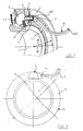
- la figure 1 est une perspective partielle en coupe axiale du roulement à capteur d'informations intégré,
- la figure 2 est une vue de face de la face extérieure du joint d'étanchéité selon un premier mode de réalisation de l'invention,
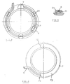
- la figure 3 est une vue de face de la face extérieure du joint d'étanchéité selon une première variante de la réalisation représentée à la figure 2,
- la figure 4 est une vue de face de la face extérieure du joint d'étanchéité selon une deuxième variante de la réalisation représentée à la figure 2,
- la figure 5 est une section du détail V de la figure 3,
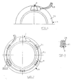
- la figure 6 est une vue de face partielle de la face extérieure du joint d'étanchéité selon un deuxième mode de réalisation de l'invention,
- la figure 7 est une vue de face de la face extérieure du joint d'étanchéité selon une variante de la réalisation représentée à la figure 6,
- la figure 8 est une section du détail VIII de la figure 7.
- Dans la suite de la description, les parties identiques ou équivalentes des roulements intégrés illustrés sur les figures porteront les mêmes numéros de référence.
- Selon la figure 1, le roulement à capteur d'informations intégré possède une bague fixe 1, une bague tournante 2, des corps roulants 3 au contact desdites bagues 1 et 2.
- La bague fixe 1 possède une gorge de réception 4 d'un joint d'étanchéité 5 sur lequel sont montés un moyen capteur 6 connu en soi et à titre d'exemple une sonde du type à effet Hall, et un manchon de protection 7 du câble 8 solidaire du joint d'étanchéité 5.
- La bague tournante 2 porte un moyen codeur 9, tel qu'un anneau magnétique multipolaire.
Cet anneau magnétique 9 est en contact avec une lèvre souple 10 portée par le joint d'étanchéité 5 qui assure une étanchéité dynamique du roulement. - Les bagues 1 et 2 possèdent également des chemins de roulement pour les corps roulants 3 disposés dans une cage 11 qui en assure la retenue et le positionnement angulaire.
- Le manchon 7 possède une gorge de réception 20 de la sonde 6 connectée au câble 8.
Ainsi le manchon 7 est à la fois une protection du câble 8 et en particulier de sa connexion avec la sonde 6, et une protection de la sonde 6 elle-même. - Par ailleurs la distance radiale A du manchon 7 par rapport à l'axe de rotation du roulement, représentée à la figure 1, est :
- soit inférieure au rayon intérieur B de la bague fixe 1 dans le but de faciliter le montage du joint 5 porteur du moyen capteur 6 sur la bague fixe 1 de roulement à l'aide d'un outil,
- soit sensiblement égale au rayon intérieur B de la bague fixe 1 de sorte que la paroi extérieure 73 du manchon 7 parallèle aux faces du roulement, puisse servir d'appui à un outil de montage du joint 5 sur ladite bague fixe 1.
- Le manchon 7 possède également une paroi d'extrémité 71 sensiblement perpendiculaire à la face extérieure 51 du joint 5, à travers laquelle débouche le câble 8 de sorte que ce dernier soit tangent à ladite face extérieure 51 du joint 5.
- Ce câble 8 possède une section rectangulaire et est constitué de conducteurs 21 répartis le long d'un côté du rectangle défini par ladite section de sorte que le câble soit plat.
- Cette disposition des conducteurs 21 correspond à un encombrement minimal pour le roulement, cependant un câble dont la section serait de toute autre forme pourrait également convenir.
- Deux côtés opposés de la section du câble 8 sont perpendiculaires à la face extérieure 51 du joint d'étanchéité 5.
- On désignera dans la suite de la description par "côté plat" 22 le côté de la section du câble 8 de plus faible épaisseur. Ce dernier est :
- soit perpendiculaire à la face extérieure 51 du joint d'étanchéité 5 selon un premier mode de réalisation de l'invention représenté aux figures 2 à 5,
- soit parallèle à la face extérieure 51 du joint d'étanchéité 5 selon un second mode de réalisation de l'invention représenté aux figures 6 à 8.
- On décrira à titre d'exemple les variantes correspondant au premier mode de réalisation de l'invention en référence aux figures 2 à 5.
- Selon la figure 2, la paroi d'extrémité 71 du manchon 7 s'arrête sur le câble 8 juste après la connexion avec la sonde 6 de sorte que la protection du manchon 7 est limitée à la sonde 6 et à sa connexion avec le câble 8.
- Selon une variante de réalisation de l'invention représentée à la figure 3, les parois d'extrémités 71 et 72 du manchon 7 le long de la face extérieure 51 du joint d'étanchéité 5 sont angulairement décalées dans le but d'augmenter la tenue du câble 8 dans le joint d'étanchéité 5.
- Dans une telle variante de réalisation, le manchon 7 peut renfermer un circuit électronique non représenté.
- Selon une autre variante de réalisation de l'invention représentée aux figures 4 et 5, le joint d'étanchéité 5 porte des moyens de retenue 24, tels que des pinces de serrage, du câble 8 disposés sur la face extérieure 51 dudit joint 5.
- Ces pinces de serrage 24 espacées régulièrement sur la face extérieure 51 de joint d'étanchéité 5 permettent un maintien provisoire du câble 8 notamment lors du montage dudit joint 5 dans la bague fixe 1, ou lors du conditionnement ou du transport du roulement.
- Cette description peut être aisément transposée aux variantes correspondant au second mode de réalisation de l'invention, telles que représentées aux figures 6 à 8.
Claims (7)
Applications Claiming Priority (2)
| Application Number | Priority Date | Filing Date | Title |
|---|---|---|---|
| FR9307745A FR2706956B1 (fr) | 1993-06-25 | 1993-06-25 | |
| FR9307745 | 1993-06-25 |
Publications (2)
| Publication Number | Publication Date |
|---|---|
| EP0631140A1 true EP0631140A1 (fr) | 1994-12-28 |
| EP0631140B1 EP0631140B1 (fr) | 1999-03-24 |
Family
ID=9448552
Family Applications (1)
| Application Number | Title | Priority Date | Filing Date |
|---|---|---|---|
| EP94401301A Expired - Lifetime EP0631140B1 (fr) | 1993-06-25 | 1994-06-10 | Roulement à capteur d'informations intégré |
Country Status (5)
| Country | Link |
|---|---|
| US (1) | US5594334A (fr) |
| EP (1) | EP0631140B1 (fr) |
| DE (1) | DE69417295T2 (fr) |
| ES (1) | ES2129599T3 (fr) |
| FR (1) | FR2706956B1 (fr) |
Cited By (3)
| Publication number | Priority date | Publication date | Assignee | Title |
|---|---|---|---|---|
| FR2723621A1 (fr) * | 1994-08-09 | 1996-02-16 | Kugelfischer G Schaefer & Co | Roulement comportant un capteur pourvu d'un cable de raccordement. |
| WO1996033124A1 (fr) * | 1995-04-21 | 1996-10-24 | Wittur Aufzugteile Gmbh & Co. | Procede de commande et de surveillance du fonctionnement d'un ascenceur, et palier a roulement destine a l'application de ce procede |
| FR2790800A1 (fr) | 1999-03-10 | 2000-09-15 | Roulements Soc Nouvelle | Ensemble preassemble formant joint d'etancheite a codeur incorpore et roulement ou palier comportant un tel ensemble |
Families Citing this family (24)
| Publication number | Priority date | Publication date | Assignee | Title |
|---|---|---|---|---|
| DE9320143U1 (de) * | 1993-12-30 | 1995-04-27 | Nord, Klaus Jürgen, 68199 Mannheim | Vorrichtung zum Steuern einer elektrischen Signaleinrichtung beim Auftreten unzulässiger Bewegungen von abgedichteten Wellen technischer Geräte |
| GB2303214B (en) * | 1995-07-07 | 1998-01-21 | Nsk Ltd | Rolling bearing unit with rotary speed sensor |
| US6007250A (en) * | 1997-10-10 | 1999-12-28 | The Torrington Company | Housed bearing with integral sensor |
| IT1303083B1 (it) * | 1998-07-27 | 2000-10-30 | Skf Ind Spa | Dispositivo per il montaggio di un sensore ad un gruppo cuscinetto diun assile ferroviario. |
| FR2792380B1 (fr) | 1999-04-14 | 2001-05-25 | Roulements Soc Nouvelle | Roulement pourvu d'un dispositif de detection des impulsions magnetiques issues d'un codeur, ledit dispositif comprenant plusieurs elements sensibles alignes |
| FR2792403B1 (fr) | 1999-04-14 | 2001-05-25 | Roulements Soc Nouvelle | Capteur de position et/ou de deplacement comportant une pluralite d'elements sensibles alignes |
| FR2792979B1 (fr) * | 1999-04-28 | 2001-05-25 | Skf France | Palier a roulement a capteur d'informations |
| JP4060037B2 (ja) * | 2001-01-15 | 2008-03-12 | Ntn株式会社 | 回転センサ付き軸受 |
| US6564635B2 (en) | 2001-09-14 | 2003-05-20 | Pete D. Sherman | Bearing assembly with integral sensor for sensing rotation |
| JP4691879B2 (ja) * | 2003-09-11 | 2011-06-01 | 日本精工株式会社 | 駆動輪用ハブユニット |
| US7318589B2 (en) * | 2003-09-22 | 2008-01-15 | Jtekt Corporation | Sealing device and rotation detector |
| DE10344234A1 (de) * | 2003-09-24 | 2005-05-12 | Fag Kugelfischer Ag | Datenerfassungs- und Verarbeitungssystem für ein Wälzlager und Wälzlager mit einem solchen System |
| FR2900209B1 (fr) * | 2006-04-20 | 2009-02-13 | Skf Ab | Dispositif de roulement instrumente |
| FR2904412B1 (fr) * | 2006-07-27 | 2008-10-17 | Snr Roulements Sa | Procede de determination de deux signaux en quadrature |
| JP2008240760A (ja) * | 2007-03-26 | 2008-10-09 | Ntn Corp | 回転センサ付き車輪軸受装置 |
| JP2008241557A (ja) * | 2007-03-28 | 2008-10-09 | Ntn Corp | 回転検出センサ |
| WO2008129808A1 (fr) * | 2007-03-28 | 2008-10-30 | Ntn Corporation | Capteur de détection de rotation |
| EP2136212A4 (fr) * | 2007-03-28 | 2012-07-25 | Ntn Toyo Bearing Co Ltd | Capteur de rotation |
| JP5063209B2 (ja) * | 2007-06-20 | 2012-10-31 | Ntn株式会社 | 回転検出センサ・固定部材取付体 |
| JP4916987B2 (ja) * | 2007-09-25 | 2012-04-18 | Ntn株式会社 | 回転検出センサ |
| JP4916986B2 (ja) * | 2007-09-25 | 2012-04-18 | Ntn株式会社 | 回転検出センサ |
| US20110127995A1 (en) * | 2008-08-11 | 2011-06-02 | Kentarou Nishikawa | Rotation sensor |
| US8876393B2 (en) * | 2010-11-30 | 2014-11-04 | Safran Power Uk Ltd. | Bearing enclosure with integrated wear detection |
| JP7035663B2 (ja) * | 2018-03-16 | 2022-03-15 | コベルコ建機株式会社 | 作業機械用冷却装置 |
Citations (4)
| Publication number | Priority date | Publication date | Assignee | Title |
|---|---|---|---|---|
| FR2649457A1 (fr) * | 1989-07-04 | 1991-01-11 | Skf France | Roulement integre muni d'un pulseur et d'un capteur pour equiper un moyeu de roue de vehicule automobile |
| EP0495323A1 (fr) * | 1991-01-15 | 1992-07-22 | Snr Roulements | Roulement à capteur d'informations |
| EP0520853A1 (fr) * | 1991-06-28 | 1992-12-30 | S.N.R. Roulements | Montage d'étanchéité pour capteur d'informations adapté à un roulement étanche |
| EP0546918A1 (fr) * | 1991-12-10 | 1993-06-16 | S.N.R. Roulements | Roulement préassemblé à éléments codeur et capteur additionnels |
Family Cites Families (8)
| Publication number | Priority date | Publication date | Assignee | Title |
|---|---|---|---|---|
| IN149928B (fr) * | 1977-07-22 | 1982-06-05 | Ransome Hoffmann Pollard | |
| US5158374A (en) * | 1988-01-07 | 1992-10-27 | The Torrington Company | Bearing or roller bearing with information sensor |
| DE3809904C2 (de) * | 1988-03-24 | 1998-12-10 | Skf Gmbh | Vorrichtung zur Abdichtung und Erzeugung von elektrischen Impulsen |
| DE3839558A1 (de) * | 1988-11-24 | 1990-05-31 | Skf Gmbh | Vorrichtung zur elektrischen verbindung von aufnehmern an lagern |
| EP0395783A1 (fr) * | 1989-05-05 | 1990-11-07 | Gmn Georg Müller Nürnberg Ag | Palier à capteur pour mesurer la vitesse de rotation et/ou l'angle de rotation |
| FR2660975B1 (fr) * | 1990-04-13 | 1992-06-19 | Roulements Soc Nouvelle | Palier a corps roulants equipe d'un dispositif capteur d'informations orientable. |
| US4988220A (en) * | 1990-05-14 | 1991-01-29 | General Motors Corporation | Servicable wheel speed sensor assembly |
| FR2671633B1 (fr) * | 1991-01-10 | 1993-04-16 | Skf France | Dispositif de capteur de vitesse de rotation integre dans un moyeu a roulement. |
-
1993
- 1993-06-25 FR FR9307745A patent/FR2706956B1/fr not_active Expired - Fee Related
-
1994
- 1994-06-10 EP EP94401301A patent/EP0631140B1/fr not_active Expired - Lifetime
- 1994-06-10 DE DE69417295T patent/DE69417295T2/de not_active Expired - Fee Related
- 1994-06-10 ES ES94401301T patent/ES2129599T3/es not_active Expired - Lifetime
-
1996
- 1996-05-17 US US08/651,198 patent/US5594334A/en not_active Expired - Lifetime
Patent Citations (4)
| Publication number | Priority date | Publication date | Assignee | Title |
|---|---|---|---|---|
| FR2649457A1 (fr) * | 1989-07-04 | 1991-01-11 | Skf France | Roulement integre muni d'un pulseur et d'un capteur pour equiper un moyeu de roue de vehicule automobile |
| EP0495323A1 (fr) * | 1991-01-15 | 1992-07-22 | Snr Roulements | Roulement à capteur d'informations |
| EP0520853A1 (fr) * | 1991-06-28 | 1992-12-30 | S.N.R. Roulements | Montage d'étanchéité pour capteur d'informations adapté à un roulement étanche |
| EP0546918A1 (fr) * | 1991-12-10 | 1993-06-16 | S.N.R. Roulements | Roulement préassemblé à éléments codeur et capteur additionnels |
Cited By (5)
| Publication number | Priority date | Publication date | Assignee | Title |
|---|---|---|---|---|
| FR2723621A1 (fr) * | 1994-08-09 | 1996-02-16 | Kugelfischer G Schaefer & Co | Roulement comportant un capteur pourvu d'un cable de raccordement. |
| WO1996033124A1 (fr) * | 1995-04-21 | 1996-10-24 | Wittur Aufzugteile Gmbh & Co. | Procede de commande et de surveillance du fonctionnement d'un ascenceur, et palier a roulement destine a l'application de ce procede |
| US6102165A (en) * | 1995-04-21 | 2000-08-15 | Wittur Ag | Antifriction bearing with signal generator and method for using same |
| RU2161117C2 (ru) * | 1995-04-21 | 2000-12-27 | Виттур АГ | Способ управления и контроля работы лифтовой установки |
| FR2790800A1 (fr) | 1999-03-10 | 2000-09-15 | Roulements Soc Nouvelle | Ensemble preassemble formant joint d'etancheite a codeur incorpore et roulement ou palier comportant un tel ensemble |
Also Published As
| Publication number | Publication date |
|---|---|
| DE69417295D1 (de) | 1999-04-29 |
| EP0631140B1 (fr) | 1999-03-24 |
| FR2706956A1 (fr) | 1994-12-30 |
| FR2706956B1 (fr) | 1995-08-18 |
| DE69417295T2 (de) | 1999-11-04 |
| US5594334A (en) | 1997-01-14 |
| ES2129599T3 (es) | 1999-06-16 |
Similar Documents
| Publication | Publication Date | Title |
|---|---|---|
| EP0631140B1 (fr) | Roulement à capteur d'informations intégré | |
| EP0926501B1 (fr) | Montage de roue de patin en ligne avec dispositif de détection de la vitesse de rotation | |
| EP0387459A2 (fr) | Montage de palier antifriction à capteur d'informations amovible | |
| FR2751707A1 (fr) | Roulement a capteur d'informations | |
| EP0872652B1 (fr) | Palier à roulement à capteur d'informations | |
| EP0371836B1 (fr) | Roulement à capteur d'informations | |
| EP0453331A1 (fr) | Palier à corps roulants équipé d'un dispositif capteur d'informations orientable | |
| EP0317423B1 (fr) | Montage de moyeu de roue non motrice de véhicule équipé d'un dispositif à pulseur et capteur pour mesure de vitesse de rotation de la roue | |
| EP0522933A1 (fr) | Capteur de vitesse de rotation et palier à roulement équipé d'un tel capteur | |
| FR2649457A1 (fr) | Roulement integre muni d'un pulseur et d'un capteur pour equiper un moyeu de roue de vehicule automobile | |
| EP0743738A1 (fr) | Alternateur, notamment pour véhicule automobile, comportant un agencement perfectionné de diodes de redressement | |
| EP0454547A1 (fr) | Moyeu à roulement équipé d'un dispositif de détection de la vitesse de rotation | |
| EP0616219A1 (fr) | Ensemble comportant joint d'étanchéité et capteur de vitesse | |
| EP0343058A1 (fr) | Montage de moyeu de roue non motrice de véhicule équipé d'un dispositif à pulseur et capteur pour mesure de la vitesse de rotation de la roue | |
| EP0173607A1 (fr) | Roulement à aiguilles, notamment douille à aiguilles à étanchéité renforcée | |
| EP1088236B1 (fr) | Roulement a codeur incorpore | |
| EP1277978A1 (fr) | Palier à corps roulants coniques pourvu d'un dispostif d'étanchéité | |
| EP0906558B1 (fr) | Arbre tournant incorporant un dispositif de mesure de couple de torsion | |
| FR2803954A1 (fr) | Motoreducteur destine a des equipements fonctionnels de vehicules, pourvu d'une bague magnetique de mesure de la vitesse de rotation de son arbre d'induit | |
| EP1251354A1 (fr) | Dispositif d'étanchéité pour palier à roulement instrumenté d'un capteur de vitesse de rotation | |
| EP1693677A1 (fr) | Dispositif de détection des paramètres de rotation de deux éléments | |
| FR2666394A1 (fr) | Ensemble d'etancheite. | |
| EP0260196A1 (fr) | Dispositif de liaison entre un groupe moto-propulseur et un arbre de transmission de véhicule | |
| EP1619478A2 (fr) | Dispositif de détection de paramètre de rotation d'une roue, notamment d'une roue de véhicule | |
| EP0702234B1 (fr) | Capteur de vitesse à effet Hall |
Legal Events
| Date | Code | Title | Description |
|---|---|---|---|
| PUAI | Public reference made under article 153(3) epc to a published international application that has entered the european phase |
Free format text: ORIGINAL CODE: 0009012 |
|
| AK | Designated contracting states |
Kind code of ref document: A1 Designated state(s): DE ES GB IT SE |
|
| 17P | Request for examination filed |
Effective date: 19950620 |
|
| 17Q | First examination report despatched |
Effective date: 19970114 |
|
| GRAG | Despatch of communication of intention to grant |
Free format text: ORIGINAL CODE: EPIDOS AGRA |
|
| GRAG | Despatch of communication of intention to grant |
Free format text: ORIGINAL CODE: EPIDOS AGRA |
|
| GRAH | Despatch of communication of intention to grant a patent |
Free format text: ORIGINAL CODE: EPIDOS IGRA |
|
| GRAH | Despatch of communication of intention to grant a patent |
Free format text: ORIGINAL CODE: EPIDOS IGRA |
|
| GRAA | (expected) grant |
Free format text: ORIGINAL CODE: 0009210 |
|
| AK | Designated contracting states |
Kind code of ref document: B1 Designated state(s): DE ES GB IT SE |
|
| ITF | It: translation for a ep patent filed | ||
| REF | Corresponds to: |
Ref document number: 69417295 Country of ref document: DE Date of ref document: 19990429 |
|
| REG | Reference to a national code |
Ref country code: ES Ref legal event code: FG2A Ref document number: 2129599 Country of ref document: ES Kind code of ref document: T3 |
|
| GBT | Gb: translation of ep patent filed (gb section 77(6)(a)/1977) |
Effective date: 19990609 |
|
| PLBE | No opposition filed within time limit |
Free format text: ORIGINAL CODE: 0009261 |
|
| STAA | Information on the status of an ep patent application or granted ep patent |
Free format text: STATUS: NO OPPOSITION FILED WITHIN TIME LIMIT |
|
| 26N | No opposition filed | ||
| PGFP | Annual fee paid to national office [announced via postgrant information from national office to epo] |
Ref country code: GB Payment date: 20000512 Year of fee payment: 7 |
|
| PGFP | Annual fee paid to national office [announced via postgrant information from national office to epo] |
Ref country code: SE Payment date: 20000526 Year of fee payment: 7 |
|
| PG25 | Lapsed in a contracting state [announced via postgrant information from national office to epo] |
Ref country code: GB Free format text: LAPSE BECAUSE OF NON-PAYMENT OF DUE FEES Effective date: 20010610 |
|
| PG25 | Lapsed in a contracting state [announced via postgrant information from national office to epo] |
Ref country code: SE Free format text: LAPSE BECAUSE OF NON-PAYMENT OF DUE FEES Effective date: 20010611 |
|
| GBPC | Gb: european patent ceased through non-payment of renewal fee |
Effective date: 20010610 |
|
| EUG | Se: european patent has lapsed |
Ref document number: 94401301.0 |
|
| PGFP | Annual fee paid to national office [announced via postgrant information from national office to epo] |
Ref country code: ES Payment date: 20040615 Year of fee payment: 11 |
|
| PG25 | Lapsed in a contracting state [announced via postgrant information from national office to epo] |
Ref country code: IT Free format text: LAPSE BECAUSE OF NON-PAYMENT OF DUE FEES Effective date: 20050610 |
|
| PG25 | Lapsed in a contracting state [announced via postgrant information from national office to epo] |
Ref country code: ES Free format text: LAPSE BECAUSE OF NON-PAYMENT OF DUE FEES Effective date: 20050611 |
|
| REG | Reference to a national code |
Ref country code: ES Ref legal event code: FD2A Effective date: 20050611 |
|
| PGFP | Annual fee paid to national office [announced via postgrant information from national office to epo] |
Ref country code: DE Payment date: 20070622 Year of fee payment: 14 |
|
| PG25 | Lapsed in a contracting state [announced via postgrant information from national office to epo] |
Ref country code: DE Free format text: LAPSE BECAUSE OF NON-PAYMENT OF DUE FEES Effective date: 20090101 |