EP0631243A2 - Alphamisschungsrechner - Google Patents
Alphamisschungsrechner Download PDFInfo
- Publication number
- EP0631243A2 EP0631243A2 EP94109558A EP94109558A EP0631243A2 EP 0631243 A2 EP0631243 A2 EP 0631243A2 EP 94109558 A EP94109558 A EP 94109558A EP 94109558 A EP94109558 A EP 94109558A EP 0631243 A2 EP0631243 A2 EP 0631243A2
- Authority
- EP
- European Patent Office
- Prior art keywords
- data
- alpha blending
- outputs
- level
- stages
- Prior art date
- Legal status (The legal status is an assumption and is not a legal conclusion. Google has not performed a legal analysis and makes no representation as to the accuracy of the status listed.)
- Withdrawn
Links
Images


Classifications
-
- G—PHYSICS
- G06—COMPUTING OR CALCULATING; COUNTING
- G06F—ELECTRIC DIGITAL DATA PROCESSING
- G06F7/00—Methods or arrangements for processing data by operating upon the order or content of the data handled
- G06F7/38—Methods or arrangements for performing computations using exclusively denominational number representation, e.g. using binary, ternary, decimal representation
- G06F7/48—Methods or arrangements for performing computations using exclusively denominational number representation, e.g. using binary, ternary, decimal representation using non-contact-making devices, e.g. tube, solid state device; using unspecified devices
- G06F7/52—Multiplying; Dividing
- G06F7/523—Multiplying only
- G06F7/53—Multiplying only in parallel-parallel fashion, i.e. both operands being entered in parallel
- G06F7/5318—Multiplying only in parallel-parallel fashion, i.e. both operands being entered in parallel with column wise addition of partial products, e.g. using Wallace tree, Dadda counters
-
- G—PHYSICS
- G06—COMPUTING OR CALCULATING; COUNTING
- G06F—ELECTRIC DIGITAL DATA PROCESSING
- G06F17/00—Digital computing or data processing equipment or methods, specially adapted for specific functions
- G06F17/10—Complex mathematical operations
Definitions
- the Present invention relates to an alpha blending calculator which executes an alpha blending calculation ⁇ X + (1- ⁇ )Y in accordance with given digital data X, Y, and ⁇ .
- alpha blending In recent years, as digital techniques progress, images are more frequently processed in the form of digital data. In various apparatuses handling such digital images, a process called "alpha blending" is often used.
- the various apparatuses include, for example, an apparatus for applying special effects to images, an apparatus for processing images, and an apparatus for producing images.
- the alpha blending process two images are blended at a predetermined ratio.
- the alpha blending is accomplished by executing an operation of Expression (1) below for every pixel included in two images.
- Expression (1) the operation shown in Expression (1) is referred to as "an alpha blending calculation”.
- X denotes a digital value of a pixel included in one image
- Y denotes a digital value of a pixel included in another image
- ⁇ denotes a predetermined blending ratio
- Japanese Laid-Open Patent Publication No. 6-83852 discloses a conventional alpha blending calculator.
- the conventional alpha blending calculator will be described with reference to Figures 7 and 8 .
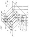
- Figure 7 shows the organization of an alpha blending calculator which executes an alpha blending calculation ⁇ X + (1- ⁇ )Y in accordance with given digital data X, Y, and ⁇ .
- Each of the digital data X, Y, and ⁇ is 4-bit binary data.
- X0 through X3 represent the least significant bit (LSB) to the most significant bit (MSB) of the digital data X, respectively.
- Y0 through Y3 represent the least significant bit (LSB) to the most significant bit (MSB) of the digital data Y, respectively.
- the digital data ⁇ is a fixed-point number with the binary point to the left of the most significant bit (MSB).
- the least significant bit (LSB) to the most significant bit (MSB) of the digital data ⁇ are represented by ⁇ 0 through ⁇ 3, respectively.
- the reference symbols P0 through P7 represent the least significant bit (LSB) to the most significant bit (MSB) of an 8-bit fixed-point number P indicative of the result of the alpha blending calculation ⁇ X + (1- ⁇ )Y .
- the binary point is located between P3 and P4.
- the alpha blending calculator includes multiplexers 71 arranged in 4 rows and 4 columns, and an adding section 74 for adding the outputs from the multiplexers 71 .
- the adding section 74 includes half adders 72 , full adders 73 , and an adder 75 which executes multi-bit addition.
- Each of the multiplexers 71 has two data lines for receiving two data inputs and one selection line for receiving selection data.
- the multiplexer 71 outputs one of two data inputs in accordance with the selection data. Respective bits of the digital data X and Y are input through the data lines of the multiplexers 71 , and respective bits of the digital data ⁇ are input through the selection lines of the multiplexers 71 .
- the outputs of the multiplexers 71 are connected to the half adders 72 and the full adders 73 .
- the half adders 72 and the full adders 73 are arranged in accordance with the organization of array multiplier.
- Expression (1) can be transformed into Expression (2) below.
- P ⁇ X + ⁇ ⁇ Y + Y2 ⁇ 4 (2)
- Expression (3) is the approximation of Expression (2).
- the difference between P obtained by Expression (2) and P obtained by Expression (3) becomes small and negligible.
- Figure 8 shows the organization of another conventional alpha blending calculator for obtaining complete P shown in Expression (2).
- the alpha blending calculator shown in Figure 8 includes multiplexers 81 and an adding section 84 for adding the outputs from the multiplexers 81 .
- the adding section 84 includes half adders 82 , full adders 83 , and an adder 85 which executes multi-bit addition.
- the organization of the alpha blending calculator shown in Figure 8 is different from the organization of the alpha blending calculator shown in Figure 7 in that Y0 - Y3 are input to the adders in the first row (stage). Accordingly, the complete alpha blending calculation shown in Expression (2) can be executed.
- the alpha blending calculators shown in Figures 7 and 8 utilize the organization of array multiplier to obtain the sum of the outputs of the multiplexers, so that a problem exists in that it is difficult to execute the calculation at a high speed.
- the alpha blending calculator of this invention for executing an alpha blending calculation in accordance with digital data X, Y, and ⁇ each composed of a plurality of bits, includes: a plurality of selection means, each of the selection means selecting one of X or Y in accordance with one of the plurality of bits of the digital data ⁇ ; and calculation means for shifting outputs of the plurality of selection means by a predetermined number of bits, respectively, and for calculating a sum of the shifted outputs, wherein the calculation means includes first level to Nth level first adding means, and adding means connected to outputs of the Nth level first adding means for executing a multi-bit addition, each of the first level to the Nth level first adding means receives a plurality of stages of data, classifies the plurality of stages of data into a plurality of quotient groups each including a predetermined number of stages of data and a remainder group including data of stages the number of which is smaller than the predetermined number, calculates a sum of the predetermined number of stages of data and
- each of the plurality of selection means is a multiplexer.
- each of the first level to Nth level first adding means includes a half adder and a full adder.
- the digital data Y is further input as the plurality of stages of data to the first level first adding means of the calculation means.
- the invention described herein makes possible the advantage of providing an alpha blending calculator of a small circuit scale which is capable of executing an alpha blending calculation at a high speed.
- Figure 1 shows the process of an alpha blending calculation according to the invention.
- Figure 2 is a diagram showing the organization of an alpha blending calculator in one example according to the invention.
- Figure 3 shows another process of an alpha blending calculation according to the invention.
- Figure 4 is a diagram schematically showing the organization of an alpha blending calculator in another example according to the invention.
- Figure 5 shows another process of an alpha blending calculation according to the invention.
- Figure 6 is a diagram schematically showing the organization of an alpha blending calculator in another example according to the invention.
- Figure 7 shows the organization of a conventional alpha blending calculator.
- Figure 8 shows the organization of another conventional alpha blending calculator.
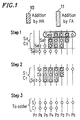
- FIG. 1 shows the process of an alpha blending calculation according to the invention.
- each of digital data X, Y, and ⁇ is 4-bit binary data.
- X0 through X3 represent the least significant bit (LSB) to the most significant bit (MSB) of the digital data X, respectively.
- Y0 through Y3 represent the least significant bit (LSB) to the most significant bit (MSB) of the digital data Y, respectively.
- the digital data ⁇ is a fixed-point number with the binary point to the left of the most significant bit (MSB).
- the least significant bit (LSB) to the most significant bit (MSB) of the digital data ⁇ are represented by ⁇ 0 through ⁇ 3, respectively.
- the reference symbols P0 through P7 represent the least significant bit (LSB) to the most significant bit (MSB) of an 8-bit fixed-point number P indicative of the result of the alpha blending calculation ⁇ X + (1- ⁇ )Y .
- the binary point is located between P3 and P4.
- step 1 to step 3 the procedure of the alpha blending calculation (step 1 to step 3) will be described.
- step 1 either one of the digital data X or Y is selected in accordance with each bit of the digital data ⁇ .
- the reference symbols Sel0, Sel1, Sel2, and Sel3 indicate the bit arrangements in which the data X or Y which are selected for the respective bits ( ⁇ 3, ⁇ 2, ⁇ 1, ⁇ 0) of the digital data ⁇ are successively shifted to the left by one bit.
- step 2 respective digits of the sum S0, the carry C0, and the Sel3 obtained in step 1 are added to each other, so as to obtain a sum S1 and a carry C1.
- the addition can be accomplished by adding the digits in a block 10 by a half adder, and by adding the digits in blocks 11 by three full adders, as shown in Figure 1 .
- step 3 the sum S1 and the carry C1 obtained in step 2 are added considering the carry. As a result, an 8-bit fixed-point number P is obtained.
- the fixed-point number P is obtained in accordance with Expression (3) shown above. Accordingly, the fixed-point number P is the approximation of the alpha blending calculation ⁇ X + (1- ⁇ )Y .
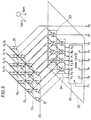
- FIG 2 shows the organization of an alpha blending calculator in one example according to the present invention.
- the alpha blending calculator executes the alpha blending calculation in accordance with the procedure shown in Figure 1 .
- the alpha blending calculator includes multiplexers 21 arranged in four rows and four columns, and an adding section 22 . Each of the multiplexers 21 selects X or Y in accordance with each bit of the digital data ⁇ .
- the adding section 22 the outputs of the multiplexers 21 are shifted by a predetermined number of bits, and the sum of the shifted outputs is obtained.
- the adding section 22 has a first level adding portion 23 , a second level adding portion 24 , and an adder 25 .
- the first level adding portion 23 is connected to the outputs of the multiplexers 21 arranged in the first to third rows, so as to execute a process corresponding to step 1 in Figure 1 .
- the first level adding portion 23 is implemented by two half adders (HA's) and two full adders (FA's).
- the second level adding portion 24 is connected to the outputs of the first level adding portion 23 and the outputs of the multiplexers 21 arranged in the fourth rows, so as to execute a process corresponding to step 2 shown in Figure 1 .
- the second level adding portion 24 is implemented by a single half ladder (HA) and three full adders (FA's).
- the adder 25 is connected to the outputs of the second level adding portion 24 , so as to execute a process corresponding to step 3 shown in Figure 1 .
- a half adder receives two single bit numbers A and B, and outputs a sum S of A and B, and a carry C to the next digit.
- Each of A, B, S, and C is "0" or "1".
- a full adder (FA) takes into account a carry C in from the previous digit. The full adder receives two single bit numbers A and B, and the carry C in , and outputs the sum S of A and B, and a carry C out to the next digit.
- Bach of A, B, S, C in , and C out is "0" or "1".
- the number of levels of addition required before the adder 25 is 2.
- the number of levels of the same addition is 3.
- the conventional alpha blending calculator having the organization of array multiplier shown in Figure 7 includes three half adders and six full adders.
- the alpha blending calculator shown in Figure 2 includes three half adders and five full adders.
- the number of adders can be reduced, so that the circuit scale of the alpha blending calculator can be minimized.
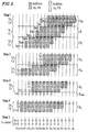
- FIG 3 shows a process of an alpha blending calculation in another example according to the invention.
- each of X, Y, and ⁇ is 8-bit binary data.
- X0 through X7 represent the least significant bit (LSB) to the most significant bit (MSB) of the digital data X, respectively.
- Y0 through Y7 represent the least significant bit (LSB) to the most significant bit (MSB) of the digital data Y, respectively.
- the digital data ⁇ is a fixed-point number with the binary point to the left of the most significant bit (MSB).
- the least significant bit (LSB) to the most significant bit (MSB) of the digital data ⁇ are represented by ⁇ 0 through ⁇ 7, respectively.
- the reference symbols P0 through P15 represent the least significant bit (LSB) to the most significant bit (MSB) of a 16-bit fixed-point number P indicative of the result of the alpha blending calculation ⁇ X + (1- ⁇ )Y .
- the binary point is located between P7 and P8.
- step 1 one of the data X or Y is selected in accordance with each bit of the digital data ⁇ .
- the reference symbols Sel0 to Sel7 indicate the bit arrangements in which the data X or Y selected for the respective bits ( ⁇ 7, ⁇ 6, ⁇ 5, ⁇ 4, ⁇ 3, ⁇ 2, ⁇ 1, ⁇ 0) are successively shifted to the left by one bit.
- a circle shows a bit of the selected data X or Y.
- the eight stages of data Sel0 to Sel7 are grouped by regarding three stages of data as a unit. As a result, Sel0 to Sel7 are classified into two quotient groups g0 and g1 , and one remainder group g rem .
- the quotient group g0 includes three stages of data Sel0 - Sel2.
- the quotient group g1 includes three stages of data Sel3 - Sel5.
- the remainder group g rem includes two stages of data Sel6 and Sel7.
- Respective digits of Sel0 to Sel2 classified into the quotient group g0 are added to each other, so as to obtain a sum S0 and a carry C0.
- the addition can be accomplished by adding the digits in blocks 30 by two half adders, and by adding the digits in blocks 31 by six full adders, as shown in Figure 3 .
- Respective digits of Sel3 to Sel5 classified into the quotient group g1 are added to each other, so as to obtain a sum S1 and a carry C1.
- the addition can be accomplished by adding the digits in blocks 30 by two half adders, and by adding the digits in blocks 31 by six full adders, as shown in Figure 3 .
- step 2 two stages of data (the sum S0 and the carry C0), two stages of data (the sum S1 and the carry C1), and the two stages of data Sel6 and Sel7 which are classified into the remainder group g rem in step 1 are grouped by regarding three stages of data as a unit. As a result, total six stages of data are classified into two quotient groups g2 and g3 .
- the quotient group g2 includes three stages of data S0, C0, and S1.
- the quotient group g3 includes three stages of data C1, Sel6, and Sel7. When 6 is divided by 3, the remainder is 0. For this reason, there is no data which is classified into the remainder group g rem .
- Respective digits of S0, C0, and S1 classified into the quotient group g2 are added to each other, so as to obtain a sum S2 and a carry C2.
- the addition can be accomplished by adding the digits in a block 30 by a half adder, and by adding the digits in blocks 31 by seven full adders, as shown in Figure 3 .
- Respective digits of C1, Sel6, and Sel7 classified into the quotient group g3 are added to each other, so as to obtain a sum S3 and a carry C3.
- the addition can be accomplished by adding the digits in blocks 30 by two half adders, and by adding the digits in blocks 31 by six full adders, as shown in Figure 3 .
- step 3 two stages of data (the sum S2 and the carry C2) and two stages of data (the sum S3 and the carry C3) are grouped by regarding three stages of data as a unit. As a result, the total four stages of data are classified into one quotient group g4 and one remainder group g rem .
- the quotient group g4 includes the three stages of data S2, C2, and S3.
- the remainder group g rem include one stage of data C3.
- Respective digits of S2, C2, and S3 classified into the quotient group g4 are added to each other, so as to obtain a sum S4 and a carry C4.
- the addition can be accomplished by adding the digits in blocks 30 by four half adders, and by adding the digits in blocks 31 by six full adders, as shown in Figure 3 .
- step 4 two stages of data (the sum S4 and the carry C4) and one stage of data C3 classified into the remainder group g rem in step 3 are grouped by regarding three stages of data as a unit. As a result, the total three stages of data are classified into one quotient group g5 .
- the quotient group g5 includes three stages of data S4, C4, and C3. When 3 is divided by 3, the remainder is 0. For this reason, there is no data which is classified into the remainder group g rem .
- Respective digits of S4, C4, and C3 classified into the quotient group g5 are added to each other, so as to obtain a sum S5 and a carry C5.
- the addition can be accomplished by adding the digits in blocks 30 by four half adders, and by adding the digits in blocks 31 by seven full adders, as shown in Figure 3 .
- the classification is executed in such a manner that the data of stages which are adjacent to each other are classified into the same group.
- the classification may be executed in such a manner that the data of stages which are not adjacent to each other are classified into the same group.
- step 5 the sum S5 and the carry C5 obtained in step 4 are added considering the carry. As a result, a 16-bit fixed-point number P is obtained.
- the fixed-point number P is obtained in accordance with Expression (3) shown above. Accordingly, the fixed-point number P is the approximation of the alpha blending calculation ⁇ X + (1- ⁇ )Y .
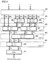
- FIG 4 schematically shows the organization of an alpha blending calculator which executes the alpha blending calculation in accordance with the procedure shown in Figure 3 .
- the alpha blending calculator includes a selector 400 for selecting X or Y in accordance with each bit of the digital data ⁇ .
- the selector 400 outputs Sel0 - Sel7 indicative of the selection results.
- the alpha blending calculator further includes first level to fourth level adding portions 401 - 404 , and an adder 411 .
- the outputs Sel0 - Sel7 of the selector 400 are input into the first level adding portion 401 .
- the first level adding portion 401 executes a process corresponding to step 1 shown in Figure 3 .
- the first level adding portion 401 is implemented by adding portions 405 and 406 each having two half adders (HA's) and six full adders (FA's).
- the adding portion 405 executes the adding process related to the quotient group g0 in step 1 of Figure 3 , and outputs the sum S0 and the carry C0 to the second level adding portion 402 .
- the adding portion 406 executes the adding process related to the quotient group g1 in step 1 of Figure 3 , and outputs the sum S1 and the carry C1 to the second level adding portion 402 .
- the outputs Sel6 and Sel7 of the selector 400 are not necessarily input into the first level adding portion 401 , because the outputs Sel6 and Sel7 are not processed in the first level adding portion 401 .
- the outputs of the adding portion 405 (the sum S0 and the carry C0), the outputs of the adding portion 406 (the sum S1 and the carry C1), and the outputs Sel6 and Sel7 of the selector 400 are input into the second level adding portion 402 .
- the second level adding portion 402 executes a process corresponding to step 2 of Figure 3 .
- the second level adding portion 402 is implemented by an adding portion 407 having a half adder (HA) and seven full adders (FA's) and an adding portion 408 having two half adders (HA's) and six full adders (FA's).
- the adding portion 407 executes the adding process related to the quotient group g2 in step 2 of Figure 3 , and outputs the sum S2 and the carry C2 to the third level adding portion 403 .
- the adding portion 408 executes the adding process related to the quotient group g3 in step 2 of Figure 3 , and outputs the sum S3 and the carry C3 to the third level adding portion 403 .
- the outputs of the adding portion 407 (the sum S2 and the carry C2) and the outputs of the adding portion 408 (the sum S3 and the carry C3) are input into the third level adding portion 403 .
- the third level adding portion 403 executes a process corresponding to step 3 of Figure 3 .
- the third level adding portion 403 is implemented by an adding portion 409 having four half adders (HA's) and six full adders (FA's).
- the adding portion 409 executes the adding process related to the quotient group g4 in step 3 of Figure 3 , and output the sum S4 and the carry C4 to the fourth level adding portion 404 .
- the carry C3 which is output from the adding portion 408 is not necessarily input into the third level adding portion 403 , because the carry C3 is not processed in the third level adding portion 403 .
- the outputs of the adding portion 409 (the sum S4 and the carry C4) and the carry C3 output from the adding portion 408 are input into the fourth level adding portion 404 .
- the fourth level adding portion 404 executes a process corresponding to step 4 of Figure 3 .
- the fourth level adding portion 404 is implemented by an adding portion 410 having four half adders (HA's) and seven full adders (FA's).
- the adding portion 410 executes the adding process related to the quotient group g5 in step 4 of Figure 3 , and outputs the sum S5 and the carry C5 to the adder 411 .
- the adder 411 adds the sum S5 and the carry C5 considering the carry, and outputs the result of addition as the 16-bit fixed-point number P.
- the number of levels of addition before the adder 411 is 4.
- the alpha blending calculator shown in Figure 4 includes 15 half adders and 38 full adders.
- the circuit scale of the alpha blending calculator in this example is slightly larger than that of the conventional one.
- the number of bits of the digital data X and Y is m
- the number of levels of addition required for the conventional alpha blending calculator having the organization of array multiplier is (m - 1)
- the process time is O(m).
- the level number L of adding processes required for the alpha blending calculator according to the invention is approximately based on Expression (5) below, so that the process time is O(log m).
- L 5.67 (log m - 0.30) (5) Therefore, the alpha blending calculator according to the invention can execute the calculation at a much higher speed as compared with the conventional alpha blending calculator having the organization of array multiplier. It is also found that, as the number m of bits of X and Y increases, the difference in process time is remarkably increased. If a carry lookahead adder is used as the adder 411 shown in Figure 4 , the process time can be further shortened.
- Figure 5 shows a process of an alpha blending calculation in another example according to the invention. In this process, a complete alpha blending calculation is realized.
- each of X, Y, and ⁇ is 8-bit binary data.
- the meanings of X0 - X7, X0 - Y7, ⁇ 0 - ⁇ 7, and P0 - P15 are the same as those described above, so that the descriptions thereof are omitted.
- the alpha blending calculation shown in Figure 5 is different from the alpha blending calculation shown in Figure 3 in that (Y7, Y6 Y5, Y4, Y3, Y2, Y1, Y0) are additionally processed in the adding process in step 1.
- step 1 nine stages of data are classified into three quotient groups g0 , g1 , and g2 by regarding three stages of data as a unit.
- step 5 (1) the classification into quotient groups and a remainder group, and (2) the addition for respective digits of the quotient groups are repeatedly executed in each step.
- step 5 the sum S6 and the carry C6 are added to each other considering the carry.
- a 16-bit fixed-point number P is obtained.
- the fixed-point number P indicates the result of the complete alpha blending calculation.
- FIG 6 schematically shows the organization of an alpha blending calculator which executes the alpha blending calculation in accordance with the procedure shown in Figure 5 .
- the alpha blending calculator includes a selector 600 for selecting one of the data X or Y in accordance with each bit of the digital data ⁇ .
- the selector 600 outputs Sel0 - Sel7 indicative of the selection results.
- the alpha blending calculator further includes first level to fourth level adding portions 601 to 604 , and an adder 612 .
- the first level to fourth level adding portions 601 to 604 execute processes corresponding to steps 1 to 4 in Figure 5 , respectively.
- the adder 612 adds the sum S6 and the carry C6 output from the fourth level adding portion 604 considering the carry, and outputs the addition result as the 16-bit fixed-point number P.
- the first level adding portion 601 is implemented by an adding portion 605 having a half adder (HA) and seven full adders (FA's), an adding portion 606 having two half adders (HA's) and six full adders (FA's), and an adding portion 607 having two half adders (HA's) and six full adders (FA's).
- the second level adding portion 602 is implemented by an adding portion 608 having a half adder (HA) and seven full adders (FA's) and an adding portion 609 having five half adders (HA's) and five full adders (FA's).
- HA half adder
- FA's full adders
- the third level adding portion 603 is implemented by an adding portion 610 having four half adders (HA's) and six full adders (FA's).
- the fourth level adding portion 604 is implemented by an adding portion 611 having five half adders (HA's) and seven full adders (FA's).
- the number of levels of addition before the adder 612 is 4.
- the conventional alpha blending calculator of the organization of array multiplier includes 7 half adders and 49 full adders.
- the alpha blending calculator shown in Figure 6 includes 20 half adders and 44 full adders.
- the circuit scale of the alpha blending calculator in this example is slightly larger than that of the conventional one.
- each of the digital data X, Y, and ⁇ is composed of 4 bits and where each of the digital data X, Y, and ⁇ is composed of 8 bits.
- the number of bits is not limited to the above-mentioned specific values.
- the present invention is suitable for executing the alpha blending calculation for digital data composed of such a large number of bits at a high speed.
- the present invention can be applied to the case where the bit width of the digital data X and Y is not equal to the bit width of the digital data ⁇ .
Landscapes
- Physics & Mathematics (AREA)
- Engineering & Computer Science (AREA)
- General Physics & Mathematics (AREA)
- Computational Mathematics (AREA)
- Mathematical Analysis (AREA)
- Mathematical Optimization (AREA)
- Pure & Applied Mathematics (AREA)
- Theoretical Computer Science (AREA)
- General Engineering & Computer Science (AREA)
- Data Mining & Analysis (AREA)
- Mathematical Physics (AREA)
- Computing Systems (AREA)
- Algebra (AREA)
- Databases & Information Systems (AREA)
- Software Systems (AREA)
- Complex Calculations (AREA)
Applications Claiming Priority (2)
| Application Number | Priority Date | Filing Date | Title |
|---|---|---|---|
| JP5150055A JPH0713741A (ja) | 1993-06-22 | 1993-06-22 | アルファ合成演算器 |
| JP150055/93 | 1993-06-22 |
Publications (2)
| Publication Number | Publication Date |
|---|---|
| EP0631243A2 true EP0631243A2 (de) | 1994-12-28 |
| EP0631243A3 EP0631243A3 (de) | 1995-05-17 |
Family
ID=15488525
Family Applications (1)
| Application Number | Title | Priority Date | Filing Date |
|---|---|---|---|
| EP94109558A Withdrawn EP0631243A3 (de) | 1993-06-22 | 1994-06-21 | Alphamisschungsrechner. |
Country Status (3)
| Country | Link |
|---|---|
| US (1) | US5517437A (de) |
| EP (1) | EP0631243A3 (de) |
| JP (1) | JPH0713741A (de) |
Cited By (1)
| Publication number | Priority date | Publication date | Assignee | Title |
|---|---|---|---|---|
| EP0862110A3 (de) * | 1997-02-28 | 1999-01-20 | Digital Equipment Corporation | Wallace-tree Multiplizierer mit Halb- und Volladdierer |
Families Citing this family (16)
| Publication number | Priority date | Publication date | Assignee | Title |
|---|---|---|---|---|
| JP3016381B2 (ja) * | 1997-10-28 | 2000-03-06 | 日本電気株式会社 | バイト入替え演算器 |
| JP3235661B2 (ja) * | 1998-03-30 | 2001-12-04 | 日本電気株式会社 | 三ハロゲン化窒素を用いたトリフェニルアミン化合物の製造方法 |
| US6498868B1 (en) | 1998-06-11 | 2002-12-24 | Xerox Corporation | Image scaling using pattern matching to select among scaling algorithms |
| JP4042215B2 (ja) * | 1998-06-15 | 2008-02-06 | ソニー株式会社 | 演算処理装置およびその方法 |
| JP2002014478A (ja) | 2000-06-30 | 2002-01-18 | Hodogaya Chem Co Ltd | 電子製品材料の精製方法 |
| US7055018B1 (en) | 2001-12-31 | 2006-05-30 | Apple Computer, Inc. | Apparatus for parallel vector table look-up |
| US6931511B1 (en) | 2001-12-31 | 2005-08-16 | Apple Computer, Inc. | Parallel vector table look-up with replicated index element vector |
| US7681013B1 (en) | 2001-12-31 | 2010-03-16 | Apple Inc. | Method for variable length decoding using multiple configurable look-up tables |
| US7034849B1 (en) * | 2001-12-31 | 2006-04-25 | Apple Computer, Inc. | Method and apparatus for image blending |
| US7467287B1 (en) | 2001-12-31 | 2008-12-16 | Apple Inc. | Method and apparatus for vector table look-up |
| US7095906B2 (en) * | 2002-07-03 | 2006-08-22 | Via Technologies, Inc. | Apparatus and method for alpha blending of digital images |
| CN100390825C (zh) | 2003-06-12 | 2008-05-28 | 微软公司 | 混合多重图象的方法 |
| TWI256036B (en) * | 2004-11-25 | 2006-06-01 | Realtek Semiconductor Corp | Method for blending digital images |
| FR2890588B1 (fr) * | 2005-09-12 | 2007-11-16 | Roctool Soc Par Actions Simpli | Dispositif de transformation de materiaux utilisant un chauffage par induction |
| US7840623B2 (en) * | 2005-09-26 | 2010-11-23 | Dai Nippon Printing Co., Ltd. | Interpolator and designing method thereof |
| JP4887821B2 (ja) * | 2006-02-15 | 2012-02-29 | 大日本印刷株式会社 | 線形補間演算器 |
Family Cites Families (6)
| Publication number | Priority date | Publication date | Assignee | Title |
|---|---|---|---|---|
| DE3267489D1 (en) * | 1982-02-18 | 1986-01-02 | Itt Ind Gmbh Deutsche | Digital parallel calculating circuit for positive and negative binary numbers |
| JPS6347874A (ja) * | 1986-08-16 | 1988-02-29 | Nec Corp | 算術演算装置 |
| US5113363A (en) * | 1989-12-29 | 1992-05-12 | Ail Systems, Inc. | Method and apparatus for computing arithmetic expressions using on-line operands and bit-serial processing |
| US5285403A (en) * | 1989-12-29 | 1994-02-08 | U.S. Philips Corporation | Arithmetic processing module to be associated with a microprocessor central processing unit |
| US5113362A (en) * | 1990-05-11 | 1992-05-12 | Analog Devices, Inc. | Integrated interpolator and method of operation |
| JPH0683852A (ja) * | 1992-08-31 | 1994-03-25 | Matsushita Electric Ind Co Ltd | アルファ合成演算器 |
-
1993
- 1993-06-22 JP JP5150055A patent/JPH0713741A/ja active Pending
-
1994
- 1994-06-21 EP EP94109558A patent/EP0631243A3/de not_active Withdrawn
- 1994-06-22 US US08/263,814 patent/US5517437A/en not_active Expired - Fee Related
Cited By (2)
| Publication number | Priority date | Publication date | Assignee | Title |
|---|---|---|---|---|
| EP0862110A3 (de) * | 1997-02-28 | 1999-01-20 | Digital Equipment Corporation | Wallace-tree Multiplizierer mit Halb- und Volladdierer |
| US6065033A (en) * | 1997-02-28 | 2000-05-16 | Digital Equipment Corporation | Wallace-tree multipliers using half and full adders |
Also Published As
| Publication number | Publication date |
|---|---|
| US5517437A (en) | 1996-05-14 |
| EP0631243A3 (de) | 1995-05-17 |
| JPH0713741A (ja) | 1995-01-17 |
Similar Documents
| Publication | Publication Date | Title |
|---|---|---|
| EP0631243A2 (de) | Alphamisschungsrechner | |
| US5880985A (en) | Efficient combined array for 2n bit n bit multiplications | |
| EP0239899B1 (de) | Matrix-strukturierte Multiplizierschaltung | |
| EP0448367A2 (de) | Digitaler paralleler Hochgeschwindigkeitsmultiplizierer | |
| EP0158530B1 (de) | Dividierer ohne Rückstellung | |
| EP0375947B1 (de) | Zweierkomplementmultiplikation mit einem Vorzeichen-/Grössen-Multiplizierer | |
| US5245564A (en) | Apparatus for multiplying operands | |
| US4831577A (en) | Digital multiplier architecture with triple array summation of partial products | |
| EP0613082A1 (de) | 4:2-Addierer und diesen verwendende Multiplizierschaltung | |
| EP0356153B1 (de) | Verfahren und Gerät zur Radix-2**n-Division mit überlappender Quotientenbitauswahl und gleichzeitiger Rundung und Korrektur des Quotienten | |
| US6370556B1 (en) | Method and arrangement in a transposed digital FIR filter for multiplying a binary input signal with tap coefficients and a method for designing a transposed digital filter | |
| EP0416308A2 (de) | Rechteckiger Matrixstrukturierter Vorzeichenziffernmultiplizierer | |
| JP3276444B2 (ja) | 除算回路 | |
| KR100308726B1 (ko) | 고속 산술 장치에서 올림수 예견가산기 스테이지의 수를 감소시키는 장치 및 방법 | |
| US5307302A (en) | Square root operation device | |
| EP0539010A2 (de) | Verfahren und Anordung zur Erzeugung von Summeinformation-/Rundungskontrolle-Signal | |
| US5278782A (en) | Square root operation device | |
| EP0428942A2 (de) | Mehrere Bit umkodierender Multiplizierer | |
| EP1049002A2 (de) | Verfahren und Gerät zum effizienten Berechnen eines annähernden Quadrats einer Festkommazahl | |
| US3842250A (en) | Circuit for implementing rounding in add/subtract logic networks | |
| US4677583A (en) | Apparatus for decimal multiplication | |
| US5867413A (en) | Fast method of floating-point multiplication and accumulation | |
| KR100290906B1 (ko) | 부동소수점곱셈기에서반올림과덧셈을동시에수행하는장치및방법 | |
| US5535148A (en) | Method and apparatus for approximating a sigmoidal response using digital circuitry | |
| JPH0312738B2 (de) |
Legal Events
| Date | Code | Title | Description |
|---|---|---|---|
| PUAI | Public reference made under article 153(3) epc to a published international application that has entered the european phase |
Free format text: ORIGINAL CODE: 0009012 |
|
| AK | Designated contracting states |
Kind code of ref document: A2 Designated state(s): DE FR GB |
|
| 17P | Request for examination filed |
Effective date: 19941121 |
|
| PUAL | Search report despatched |
Free format text: ORIGINAL CODE: 0009013 |
|
| AK | Designated contracting states |
Kind code of ref document: A3 Designated state(s): DE FR GB |
|
| 17Q | First examination report despatched |
Effective date: 19981013 |
|
| STAA | Information on the status of an ep patent application or granted ep patent |
Free format text: STATUS: THE APPLICATION HAS BEEN WITHDRAWN |
|
| 18W | Application withdrawn |
Withdrawal date: 19990122 |