EP0631332B1 - Procédé de fabrication d'une couche mince supraconductrice en Y-Ba-Cu-O - Google Patents
Procédé de fabrication d'une couche mince supraconductrice en Y-Ba-Cu-O Download PDFInfo
- Publication number
- EP0631332B1 EP0631332B1 EP94109729A EP94109729A EP0631332B1 EP 0631332 B1 EP0631332 B1 EP 0631332B1 EP 94109729 A EP94109729 A EP 94109729A EP 94109729 A EP94109729 A EP 94109729A EP 0631332 B1 EP0631332 B1 EP 0631332B1
- Authority
- EP
- European Patent Office
- Prior art keywords
- voltage
- target
- substrate
- film formation
- film
- Prior art date
- Legal status (The legal status is an assumption and is not a legal conclusion. Google has not performed a legal analysis and makes no representation as to the accuracy of the status listed.)
- Expired - Lifetime
Links
Images

Classifications
-
- C—CHEMISTRY; METALLURGY
- C23—COATING METALLIC MATERIAL; COATING MATERIAL WITH METALLIC MATERIAL; CHEMICAL SURFACE TREATMENT; DIFFUSION TREATMENT OF METALLIC MATERIAL; COATING BY VACUUM EVAPORATION, BY SPUTTERING, BY ION IMPLANTATION OR BY CHEMICAL VAPOUR DEPOSITION, IN GENERAL; INHIBITING CORROSION OF METALLIC MATERIAL OR INCRUSTATION IN GENERAL
- C23C—COATING METALLIC MATERIAL; COATING MATERIAL WITH METALLIC MATERIAL; SURFACE TREATMENT OF METALLIC MATERIAL BY DIFFUSION INTO THE SURFACE, BY CHEMICAL CONVERSION OR SUBSTITUTION; COATING BY VACUUM EVAPORATION, BY SPUTTERING, BY ION IMPLANTATION OR BY CHEMICAL VAPOUR DEPOSITION, IN GENERAL
- C23C14/00—Coating by vacuum evaporation, by sputtering or by ion implantation of the coating forming material
- C23C14/22—Coating by vacuum evaporation, by sputtering or by ion implantation of the coating forming material characterised by the process of coating
- C23C14/34—Sputtering
- C23C14/3435—Applying energy to the substrate during sputtering
-
- C—CHEMISTRY; METALLURGY
- C23—COATING METALLIC MATERIAL; COATING MATERIAL WITH METALLIC MATERIAL; CHEMICAL SURFACE TREATMENT; DIFFUSION TREATMENT OF METALLIC MATERIAL; COATING BY VACUUM EVAPORATION, BY SPUTTERING, BY ION IMPLANTATION OR BY CHEMICAL VAPOUR DEPOSITION, IN GENERAL; INHIBITING CORROSION OF METALLIC MATERIAL OR INCRUSTATION IN GENERAL
- C23C—COATING METALLIC MATERIAL; COATING MATERIAL WITH METALLIC MATERIAL; SURFACE TREATMENT OF METALLIC MATERIAL BY DIFFUSION INTO THE SURFACE, BY CHEMICAL CONVERSION OR SUBSTITUTION; COATING BY VACUUM EVAPORATION, BY SPUTTERING, BY ION IMPLANTATION OR BY CHEMICAL VAPOUR DEPOSITION, IN GENERAL
- C23C14/00—Coating by vacuum evaporation, by sputtering or by ion implantation of the coating forming material
- C23C14/06—Coating by vacuum evaporation, by sputtering or by ion implantation of the coating forming material characterised by the coating material
- C23C14/08—Oxides
- C23C14/087—Oxides of copper or solid solutions thereof
-
- C—CHEMISTRY; METALLURGY
- C23—COATING METALLIC MATERIAL; COATING MATERIAL WITH METALLIC MATERIAL; CHEMICAL SURFACE TREATMENT; DIFFUSION TREATMENT OF METALLIC MATERIAL; COATING BY VACUUM EVAPORATION, BY SPUTTERING, BY ION IMPLANTATION OR BY CHEMICAL VAPOUR DEPOSITION, IN GENERAL; INHIBITING CORROSION OF METALLIC MATERIAL OR INCRUSTATION IN GENERAL
- C23C—COATING METALLIC MATERIAL; COATING MATERIAL WITH METALLIC MATERIAL; SURFACE TREATMENT OF METALLIC MATERIAL BY DIFFUSION INTO THE SURFACE, BY CHEMICAL CONVERSION OR SUBSTITUTION; COATING BY VACUUM EVAPORATION, BY SPUTTERING, BY ION IMPLANTATION OR BY CHEMICAL VAPOUR DEPOSITION, IN GENERAL
- C23C14/00—Coating by vacuum evaporation, by sputtering or by ion implantation of the coating forming material
- C23C14/22—Coating by vacuum evaporation, by sputtering or by ion implantation of the coating forming material characterised by the process of coating
- C23C14/34—Sputtering
- C23C14/35—Sputtering by application of a magnetic field, e.g. magnetron sputtering
-
- H—ELECTRICITY
- H10—SEMICONDUCTOR DEVICES; ELECTRIC SOLID-STATE DEVICES NOT OTHERWISE PROVIDED FOR
- H10N—ELECTRIC SOLID-STATE DEVICES NOT OTHERWISE PROVIDED FOR
- H10N60/00—Superconducting devices
- H10N60/01—Manufacture or treatment
- H10N60/0268—Manufacture or treatment of devices comprising copper oxide
- H10N60/0296—Processes for depositing or forming copper oxide superconductor layers
- H10N60/0408—Processes for depositing or forming copper oxide superconductor layers by sputtering
Definitions
- the present invention relates to a method of manufacturing Y-Ba-Cu-O (hereinafter referred to as YBCO) superconducting thin films having excellent crystallinity using a sputtering phenomenon. More particularly, the present invention relates to a method of optimizing film formation conditions so that the composition ratio of Y:Ba:Cu of a film becomes 1:2:3.
- the film is suitable for use in the electronics field of sensors, electronic devices or the like using thin films.
- the hybrid plasma sputtering method is available as a parallel plate sputtering method for forming Y-Ba-Cu-O type superconducting thin films on substrates.
- the characteristic feature of the hybrid plasma sputtering method is that a high-frequency voltage is applied to the cathode electrode being superimposed on a DC voltage supplied through a low-path filter which cuts off the high-frequency voltage, wherein a conductive YBCO target is placed on the cathode and sputtered in a low vacuum.
- YBCO thin films having excellent crystallinity can be obtained (see, for example, W.Ito et al., "Highest Crystallinity of a-axis YBCO films by DC-94.92 MHz Hybrid Plasma Magnetron Sputtering", Physica C 204(1993) pp.295-298).
- a bias voltage applied from a DC power source when a bias voltage applied from a DC power source is increased at the same time as a high-frequency voltage is applied to the cathode electrode, an electric current increases sharply from a certain voltage, in correspondence with the conductance of a target, and enters into a so-called constant voltage region as shown in Fig. 7.
- a DC plasma is superimposed on a high-frequency plasma (hereinafter referred to as a hybrid plasma state).
- a hybrid plasma state Use of such plasma makes it possible to speed up the film formation while maintaining the advantage of the high-frequency plasma which contributes to crystallinity.
- the target voltage is a voltage in which a negative bias voltage generated by a DC power source is superimposed on the self bias on the cathode side generated by the high-frequency plasma which is caused by a high-frequency voltage applied to a YBa 2 Cu 3 O x target.
- the target current is the electric current which flows when the target voltage is applied.
- the film formation conditions By optimizing the film formation conditions by using the hybrid plasma sputtering method so that the composition ratio of Y:Ba:Cu of the film becomes 1:2:3, it is possible to manufacture a YBCO thin film whose crystallinity is optimized automatically.
- An example of the optimized film formation conditions is as follows: the film formation pressure : 63,2 Pa (475 mTorr), the flow-rate ratio of sputtering gas Ar to reaction gas 02: 2:1, the RF output: 60 W, the cathode voltage: -100 V, and the cathode current: 0.5 A.
- the cathode voltage is the value of the voltage in the constant voltage region of the characteristic shown in Fig. 7. This voltage is dependent on the conductance, or the resistance of the target. Therefore, the value of the cathode voltage in the constant voltage region depends upon the target used. When, for example, a target having a low conductance is used, a voltage drop at the cathode which is necessary for generating a hybrid plasma increases.
- the film has a major problem as to its crystallinity and surface morphology (surface smoothness) .
- the results obtained thus far reveal that, when the cathode voltage in the constant voltage region falls below -100 V by tens of volts, desired crystallinity cannot be obtained even if the composition of the film is optimized by controlling other film formation parameters.
- the hybrid plasma sputtering method is a method which is sensitive to, and very restricted with regard to, the conductance of a target used. It seems that the method has a problem as a practical film formation method when the yield of the film with respect to the target is considered.
- Jpn. J. Appl. Phys., Vol. 30, No. 6A, Part 2, 1991, pages L993 to L996, "Substrate Bias and Pressure Effect on Formation of YBaCuO Thin Films in RF Magnetron Sputtering System" by A. Nakagawa et al. discloses the substrate bias and pressure effect of Y-Ba-Cu-O thin films in rf magnetron sputtering systems.
- the experiments described in this document are conducted with a negative and positive DC voltage applied to the substrate.
- This system employs a rf magnetron sputtering method which is different from the parallel plate type sputtering method wherein a negative DC voltage is applied to the target in superposition with an applied rf voltage.
- the present invention solves the above-described problems of the prior art. It is an object of the present invention to provide a method of manufacturing YBCO superconducting thin films capable of manufacturing YBa 2 Cu 3 O x superconducting thin films having high crystallinity with a high yield by introducing a new film formation parameter in a hybrid plasma sputtering method.
- the object is achieved by the method of claim 1.
- a DC bias hereinafter referred to as a substrate bias
- the film formation conditions are controlled on the basis of a difference between the voltage drops in each ion sheath formed on the substrate and directly on the target.
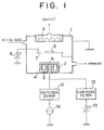
- Fig. 1 is a schematic view illustrating a film formation apparatus according to the present invention.
- the present invention is not limited to this apparatus, and it is possible to modify this apparatus within the scope of the invention.
- a mixture gas of argon and oxygen is introduced into a film formation chamber 1 evacuated to the order of 1,33 ⁇ 10 -5 Pa (1 x 10 -7 Torr), and a predetermined pressure is formed by controlling the exhaust speed.
- a YBCO target 5 having a Y:Ba:Cu composition ratio of 1:2:3 is placed on a cathode 4 in which magnets 2 and cooling water passages 3 are provided, and a substrate 6 is set directly above the YBCO target 5 at a distance of approximately 30 mm therefrom upon a substrate holder 7.
- a DC power source 8 is connected to the substrate holder 7, and a positive or negative substrate bias can be applied by switching the terminal of the power source 8.
- the substrate 6 is heated to a predetermined temperature by a heater 9 on the rear side.
- a high-frequency (94.92 MHz) power source 10 is connected to the cathode 4 via a matching device 11 so that a high-frequency voltage is applied.
- a negative bias is superimposed on the high-frequency voltage by a DC power source 13 connected via a low-path filter 12.
- SrTiO 3 and MgO are used for the substrate 6.
- the substrate bias As a parameter for film formation, it is necessary to examine an influence of the polarity of the substrate bias upon the film.
- the results of the experiment of the substrate bias under the film formation conditions of the total pressure of 63,2 Pa (475 mTorr), the argon-oxygen ratio of 1:2, the target voltage of -130 V, the target current of 0.5 A, and the substrate temperature of 650C will be explained below.
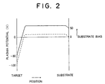
- the positive substrate bias translates upwardly the potential profile of a plasma generated between the substrate 6 and the target 5 and does not exert an influence upon plasma particles hitting on the target 5 or deposition particles which reach the substrate.
- Fig. 2 shows the profile characteristic of the plasma potential generated when a substrate bias of +50 V is applied.
- the characteristic of the plasma potential indicated by the dotted line is the characteristic obtained when the DC power source 8 is set at 0 V and the substrate 6 is grounded.
- the characteristic of the plasma potential indicated by the solid line is the characteristic obtained when a voltage 50 V is applied to the substrate holder 7 by the DC power source 8.
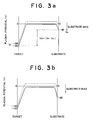
- the plasma potential profiles at this time may be presumed to be those of Figs. 3a and 3b on the basis of the observed electrical potentials of the target 5 and the substrate 6. It can be seen that these potential profiles are in agreement with the results of Table 1.
- Table 1 when a bias voltage of -40 V was applied as the substrate bias from the DC power source 8, the potential profile shown in Fig. 3a is formed, and when a bias voltage of -80 V is applied, the potential profile shown in Fig. 3b is formed.
- the positive substrate bias does not exert an influence upon film formation, whereas the negative substrate bias can be a film formation parameter which decreases the resputtering effect.
- the substrate bias is set in a range from 0 to 150 V. If the characteristics of DC plasma are intensified too much in the hybrid plasma sputtering method, it becomes impossible to use the characteristics of the high-frequency plasma.
- the upper limit of the negative DC voltage applied to the cathode 4 from the DC power source 13 is set at 200 V, and as a result the negative DC current is limited to 1 A or less.
- the method has the advantage that an a-axis orientation film having excellent orientation and crystallinity free from a hetero-phase can be obtained without depending upon a target by a method in which a high-frequency voltage and a DC voltage are superimposed on each other and applied to a cathode electrode at the same time, an electroconductive YBCO target is placed on the target, a DC voltage is applied to a substrate holder so that the film formation conditions are controlled on the basis of a difference between voltage drops in each ion sheath formed on the substrate or directly on the target.
- the characteristics of the high-frequency plasma while limiting the intensification of the DC plasma characteristics in the hybrid plasma sputtering method by controlling the negative DC voltage superimposed on a self bias on the cathode side generated by high-frequency plasma resulting from the application of the above high-frequency voltage so that the voltage is in the range from 0 to 200 V, making it possible to obtain desired crystallinity.
- the substrate bias is an effective film formation parameter in the hybrid plasma sputtering method.
- the details of how problems to be solved are made clean in the hybrid plasma sputtering method will be explained first.
- Vt the target voltage (the same as the cathode voltage) in a hybrid plasma state
- Vt the target voltage (the same as the cathode voltage) in a hybrid plasma state
- a comparative film formation experiment was conducted by using two kinds of targets #1 and #2 having different conductances with a view to manufacturing an a-axis orientation YBa 2 Cu 3 O x thin film (the a-axis of the YBa 2 Cu 3 O x structure is perpendicular to the substrate).
- the reason why the total pressure and the argon-O 2 ratio differ in Table 2 is that the target voltage V t of each target is reflected.
- the hybrid plasma state is achieved when the target voltage enters a constant voltage region.
- the difference to be noted between the targets #1 and #2 shown in Table 2 is a voltage value at that time.
- the target voltage of the target #2 entering the constant voltage region is -130 V, which is greater than that in the case of target #1. This is attributable to the fact that the electrical resistance of the target is greater.
- the difference of the film formation conditions for the targets can be explained by the condition of the target voltage.
- target #2 having a high target voltage during film formation When target #2 having a high target voltage during film formation is used, the acceleration of the negative oxygen ions in the ion sheath formed directly on the target 5 is promoted. To suppress an increase of the resputtering effect as a result of the above acceleration thereof, the film formation pressure becomes higher than that of target #1.
- the reason why the electrical resistance of the target is high can be understood when the mixture ratio of argon to oxygen is considered to be attributable to the deficiency of oxygen contained in the target.
- the matter to be noted particularly is that the crystallinity or orientation of the film obtained by sputtering two kinds of targets characterized by the above differences of the film formation conditions differs greatly when a target to be sputtered is different in spite of the fact that the composition ratio of Y:Ba:Cu of the film is both 1:2:3.
- target #1 When target #1 was used, it was confirmed by an X-ray diffraction method that the crystallinity of the film was optimized automatically by optimizing the composition of the film, and a high-quality a-axis orientation film can be obtained.
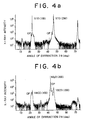
- Figs. 4a and 4b show the crystal orientation patterns, obtained by an X-ray diffraction method, of a YBCO thin film produced on each of an SrTiO 3 substrate (represented as STO) and an MgO substrate using target #2. Along the horizontal axis is plotted the angle of diffraction, and along the vertical axis is plotted the X-ray intensity.
- Fig. 4a shows the crystal orientation pattern on the SrTiO 3 substrate
- Fig. 4b shows a crystal orientation pattern on the MgO substrate. Since the peaks of the crystal orientation pattern (n00) of the film on the SrTiO 3 substrate overlap with those of the substrate and hence cannot be confirmed, the results on the MgO substrate are also shown in Fig. 4b in a corresponding manner. The peaks corresponding to the hetero-phase are indicated by OP.
- the method of calculating the a-axis length (the lattice or diffraction space) of YBCO on the MgO substrate will be explained briefly using Fig. 4b as an example.
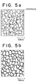
- Fig. 5a is a schematic view illustrating the structure of the film of Fig. 4a
- Fig. 5b is a schematic view illustrating the structure of the film of Fig. 4b.
- target #1 On the basis of the above results, our ideal target is target #1, and target #2 is an inappropriate target. However, it is not possible to always obtain a target such as target #1. Whether the target is appropriate or not can be known when it is disposed in the cathode 4 and a plasma is generated. Therefore, when a great amount of time required to replace a target and a yield of targets are considered, the hybrid plasma sputtering method has problems as a practical film formation method when applied to manufacturing devices.
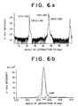
- Figs. 6a and 6b show the results of the orientation and crystallinity evaluation of the obtained film by an X-ray diffraction method.
- Fig. 6a shows the X-ray intensity pattern obtained by an X-ray diffraction method with respecy to a YBCO thin film using a target #2 and applying a substrate bias of -40 V
- Fig. 6b shows a rocking curve of the peak of a crystal orientation pattern (200) of the film.
- the second embodiment describes the a-axis orientation film
- this embodiment may be applied to manufacturing a film having other orientations, for example, c-axis orientation films. Since, as described above, the value of V t varies depending upon the target, it is necessary for the substrate bias applied to obtain V d appropriate for the orientation of the film to be variable. However, when the negative substrate bias exceeds 150 V, sputtering on the side of the substrate by positive argon ions becomes marked, deteriorating the film. Therefore, the substrate bias should be from 0 to 150 V.
- the upper limit of a negative DC voltage applied to the cathode 4 is set at 200 V, and in correspondence with this, the negative DC current is limited to 1 A or less.
- the sputtering pressure should preferably be set at from 26,6 Pa (200 mTorr) to 266 Pa (2 Torr).
- the substrate temperature during film formation is an important film formation parameter for YBCO crystallization in the same manner as in other film formation methods.
- the substrate temperature is 600°C or less, the YBCO structure is not formed.
- the substrate temperature is 900°C or more, the surface morphology is considerably deteriorated due to redeposition or the like. Therefore, the substrate bias is set at from 600°C to 900°C.
- the intensification of the DC plasma characteristics are limited by limiting a DC current to be superimposed on a self bias on the cathode side, generated by a high-frequency plasma caused by the application of a high-frequency voltage, in the range of more than 0 mA to 1 A or less.
- a DC current to be superimposed on a self bias on the cathode side, generated by a high-frequency plasma caused by the application of a high-frequency voltage, in the range of more than 0 mA to 1 A or less.
- YBCO crystallization is made possible while securing a substrate temperature necessary for forming a YBCO structure without deteriorating the surface morphology by forming a film in a temperature range of 600°C to 900°C.
- the hybrid plasma sputtering method has the problem that the yield of the film with respect to the target is poor.
- the above-described problems are solved by introducing a substrate bias and controlling a new film formation parameter of Vd, which is a difference between the voltage drops in the ion sheaths formed on the substrate and directly on each target.
- Vd a new film formation parameter of Vd
Landscapes
- Chemical & Material Sciences (AREA)
- Engineering & Computer Science (AREA)
- Chemical Kinetics & Catalysis (AREA)
- Materials Engineering (AREA)
- Mechanical Engineering (AREA)
- Metallurgy (AREA)
- Organic Chemistry (AREA)
- Manufacturing & Machinery (AREA)
- Superconductor Devices And Manufacturing Methods Thereof (AREA)
- Physical Vapour Deposition (AREA)
- Inorganic Compounds Of Heavy Metals (AREA)
- Crystals, And After-Treatments Of Crystals (AREA)
Claims (11)
- Procédé pour la fabrication d'une couche mince supraconductrice en Y-Ba-Cu-O sur un substrat (6) en faisant appel à un procédé de pulvérisation du type à plaques parallèles, comprenant les étapes consistant à :mettre en place une cible YBCO (5) conductrice électriquement sur une électrode cathodique (4) à l'intérieur d'une chambre de formation de film (1) sous un léger vide, cette chambre de formation de film (1) étant maintenue dans une plage de basse pression prédéterminée, et mettre en place le substrat (6) entre les deux plaques d'électrode directement au-dessus de la cible (5) via un support de substrat (7); etsuperposer une tension haute fréquence sur la tension CC négative et l'appliquer sur l'électrode cathodique (4) ;caractérisé par les étapes consistant à :appliquer une tension CC négative sur le support de substrat (7) ; etcontrôler les conditions de formation de film en fonction du paramètre Vd = |Vt - Vs|, où Vt et Vs désignent les chutes de tension dans les gaines ioniques formées directement au-dessus de la cible YBCO (5) et du substrat (6) respectivement.
- Procédé selon la revendication 1, dans lequel la tension CC négative qui est contrôlée comme étant l'une des conditions de formation de film et appliquée sur le support de substrat (7) se situe dans la plage de 0 à 150 V.
- Procédé selon la revendication 1, dans lequel la tension CC négative qui est contrôlée comme étant l'une des conditions de formation de film et superposée sur une autopolarisation de l'électrode cathodique (4), générée par un plasma haute fréquence provoqué par l'application de la tension haute fréquence, se situe dans une plage dépassant 0 et allant jusqu'à 200 V.
- Procédé selon la revendication 1, dans lequel le courant CC qui est contrôlé comme étant l'une des conditions de formation de film et superposé sur une autopolarisation. de l'électrode cathodique (4), généré par un plasma haute fréquence produit par l'application de la tension haute fréquence, se situe dans une plage dépassant 0 mA et allant jusqu'à 1 A.
- Procédé selon la revendication 1, dans lequel la plage basse pression prédéterminée est de 26,6 à 266 Pa (200 mTorrs jusqu'à 2 Torrs).
- Procédé selon la revendication 1, dans lequel la température qui est contrôlée comme étant l'une des conditions de formation de film et à laquelle est chauffé le substrat (6) se situe dans la plage de 600°C à 900°C.
- Procédé selon la revendication 1, dans lequel un plasma hybride obtenu par superposition d'un plasma CC généré par application d'une tension CC négative sur un plasma haute fréquence généré par application de la tension haute fréquence sert à former un film.
- Procédé selon la revendication 1, dans lequel la cible YBCO (5) est une cible YBa2Cu3Ox (5) dans laquelle le rapport de composition de Y:Ba:Cu est ajusté à 1:2:3.
- Procédé selon la revendication 1, dans lequel le substrat (6) est réalisé à partir d'un matériau sélectionné à partir du groupe constitué par SrTiO3 et MgO.
- Procédé selon la revendication 1, dans lequel un gaz de mélange d'argon et d'oxygène est introduit dans la chambre de formation de film.
- Procédé selon la revendication 1, dans lequel le paramètre Vd est contrôlé jusqu'à 100 V, permettant ainsi d'obtenir un film d'orientation d'axe a.
Applications Claiming Priority (2)
| Application Number | Priority Date | Filing Date | Title |
|---|---|---|---|
| JP153824/93 | 1993-06-24 | ||
| JP5153824A JPH0715051A (ja) | 1993-06-24 | 1993-06-24 | Ybco超電導薄膜の製造方法 |
Publications (2)
| Publication Number | Publication Date |
|---|---|
| EP0631332A1 EP0631332A1 (fr) | 1994-12-28 |
| EP0631332B1 true EP0631332B1 (fr) | 1997-04-16 |
Family
ID=15570898
Family Applications (1)
| Application Number | Title | Priority Date | Filing Date |
|---|---|---|---|
| EP94109729A Expired - Lifetime EP0631332B1 (fr) | 1993-06-24 | 1994-06-23 | Procédé de fabrication d'une couche mince supraconductrice en Y-Ba-Cu-O |
Country Status (4)
| Country | Link |
|---|---|
| US (1) | US5466665A (fr) |
| EP (1) | EP0631332B1 (fr) |
| JP (1) | JPH0715051A (fr) |
| DE (1) | DE69402619T2 (fr) |
Families Citing this family (6)
| Publication number | Priority date | Publication date | Assignee | Title |
|---|---|---|---|---|
| US20030094239A1 (en) * | 2000-06-02 | 2003-05-22 | Quon Bill H. | Apparatus and method for improving electron ecceleration |
| US6413380B1 (en) * | 2000-08-14 | 2002-07-02 | International Business Machines Corporation | Method and apparatus for providing deposited layer structures and articles so produced |
| EP1905867A1 (fr) * | 2006-09-28 | 2008-04-02 | Fujifilm Corporation | Procédé de formation d'un film, film piézoélectrique, et dispositif piézoélectrique |
| JP5178832B2 (ja) * | 2007-07-25 | 2013-04-10 | ジーエス ナノテク カンパニー リミテッド | 非電導性ターゲットを使用するスパッタリングによるセラミック薄膜の成膜方法 |
| US8540851B2 (en) * | 2009-02-19 | 2013-09-24 | Fujifilm Corporation | Physical vapor deposition with impedance matching network |
| CN112962076B (zh) * | 2021-02-04 | 2022-04-05 | 西南交通大学 | 一种二代高温超导带材金属前驱膜的制备方法 |
Family Cites Families (10)
| Publication number | Priority date | Publication date | Assignee | Title |
|---|---|---|---|---|
| US3461054A (en) * | 1966-03-24 | 1969-08-12 | Bell Telephone Labor Inc | Cathodic sputtering from a cathodically biased target electrode having an rf potential superimposed on the cathodic bias |
| CA1331868C (fr) * | 1987-03-14 | 1994-09-06 | Nobuhiko Fujita | Procede de depot de couche mince supraconductrice |
| US5236894A (en) * | 1987-12-26 | 1993-08-17 | Sumitomo Electric Industries, Ltd. | Process for producing a superconducting thin film at relatively low temperature |
| US5361720A (en) * | 1988-04-22 | 1994-11-08 | British Technology Group Ltd. | Epitaxial deposition |
| DE3821207A1 (de) * | 1988-06-23 | 1989-12-28 | Leybold Ag | Anordnung zum beschichten eines substrats mit dielektrika |
| JP2936276B2 (ja) * | 1990-02-27 | 1999-08-23 | 日本真空技術株式会社 | 透明導電膜の製造方法およびその製造装置 |
| EP0462906B1 (fr) * | 1990-06-21 | 1996-04-24 | Sumitomo Electric Industries, Ltd. | Procédé et appareil pour la préparation de films minces supraconducteurs |
| JPH04219301A (ja) * | 1990-07-25 | 1992-08-10 | Semiconductor Energy Lab Co Ltd | 酸化物超伝導薄膜の作製方法 |
| DE59207306D1 (de) * | 1991-04-12 | 1996-11-14 | Balzers Hochvakuum | Verfahren und Anlage zur Beschichtung mindestens eines Gegenstandes |
| JP2905342B2 (ja) * | 1992-09-07 | 1999-06-14 | 財団法人国際超電導産業技術研究センター | YBa2Cu3Ox超電導薄膜の製造方法 |
-
1993
- 1993-06-24 JP JP5153824A patent/JPH0715051A/ja active Pending
-
1994
- 1994-06-16 US US08/263,957 patent/US5466665A/en not_active Expired - Fee Related
- 1994-06-23 DE DE69402619T patent/DE69402619T2/de not_active Expired - Fee Related
- 1994-06-23 EP EP94109729A patent/EP0631332B1/fr not_active Expired - Lifetime
Also Published As
| Publication number | Publication date |
|---|---|
| DE69402619D1 (de) | 1997-05-22 |
| JPH0715051A (ja) | 1995-01-17 |
| US5466665A (en) | 1995-11-14 |
| DE69402619T2 (de) | 1997-09-18 |
| EP0631332A1 (fr) | 1994-12-28 |
Similar Documents
| Publication | Publication Date | Title |
|---|---|---|
| EP0905723B1 (fr) | Matériaux diélectriques amorphes et condensateurs utilisant ceux-ci | |
| US5977582A (en) | Capacitor comprising improved TaOx -based dielectric | |
| EP0441408B1 (fr) | Procédé de fabrication d'un film ferroélectrique | |
| US5466665A (en) | Method of manufacturing Y-Ba-Cu-O superconducting thin film | |
| US5106821A (en) | Process for forming thin oxide film | |
| US5679625A (en) | Method of making an oxide superconducting thin film | |
| US5225393A (en) | Process for forming thin oxide film | |
| US3726776A (en) | Sputtering process for producing single crystal thin films | |
| JP2547204B2 (ja) | チタン酸ビスマス薄膜の形成方法 | |
| JP2547203B2 (ja) | チタン酸ビスマス薄膜の形成方法 | |
| JPH05147933A (ja) | アモルフアス強誘電体酸化物材料及びその製造方法 | |
| JP3831433B2 (ja) | 透明導電膜およびその製造方法 | |
| Kellett et al. | Ion beam sputter deposition of YBa2Cu3O7− δ thin films | |
| EP0321071A1 (fr) | Méthode pour faire des films minces supraconducteurs | |
| Grigorov et al. | Layered structures HTSC/ferroelectric, prepared by sputtering | |
| Dedyk | Layered Structures HTSC/Ferroelectric, Prepared by Sputtering | |
| JPH05139730A (ja) | アモルフアス強誘電体酸化物材料及びその製造方法 | |
| JPH05147940A (ja) | アモルフアス強誘電体酸化物材料及びその製造方法 | |
| JPH05147936A (ja) | アモルフアス強誘電体酸化物材料及びその製造方法 | |
| JPH05151823A (ja) | アモルフアス強誘電体酸化物材料及びその製造方法 | |
| JPH05147939A (ja) | アモルフアス強誘電体酸化物材料及びその製造方法 | |
| JPH05105431A (ja) | アモルフアス強誘電体酸化物材料及びその製造方法 | |
| JPH05147935A (ja) | アモルフアス強誘電体酸化物材料及びその製造方法 | |
| JPH0517127A (ja) | アモルフアス強誘電体酸化物材料及びその製造方法 | |
| JPH05105440A (ja) | アモルフアス強誘電体酸化物材料及びその製造方法 |
Legal Events
| Date | Code | Title | Description |
|---|---|---|---|
| PUAI | Public reference made under article 153(3) epc to a published international application that has entered the european phase |
Free format text: ORIGINAL CODE: 0009012 |
|
| AK | Designated contracting states |
Kind code of ref document: A1 Designated state(s): DE FR GB |
|
| 17P | Request for examination filed |
Effective date: 19950427 |
|
| 17Q | First examination report despatched |
Effective date: 19951121 |
|
| GRAG | Despatch of communication of intention to grant |
Free format text: ORIGINAL CODE: EPIDOS AGRA |
|
| GRAH | Despatch of communication of intention to grant a patent |
Free format text: ORIGINAL CODE: EPIDOS IGRA |
|
| GRAH | Despatch of communication of intention to grant a patent |
Free format text: ORIGINAL CODE: EPIDOS IGRA |
|
| GRAA | (expected) grant |
Free format text: ORIGINAL CODE: 0009210 |
|
| AK | Designated contracting states |
Kind code of ref document: B1 Designated state(s): DE FR GB |
|
| REF | Corresponds to: |
Ref document number: 69402619 Country of ref document: DE Date of ref document: 19970522 |
|
| ET | Fr: translation filed | ||
| PLBE | No opposition filed within time limit |
Free format text: ORIGINAL CODE: 0009261 |
|
| STAA | Information on the status of an ep patent application or granted ep patent |
Free format text: STATUS: NO OPPOSITION FILED WITHIN TIME LIMIT |
|
| 26N | No opposition filed | ||
| REG | Reference to a national code |
Ref country code: GB Ref legal event code: IF02 |
|
| REG | Reference to a national code |
Ref country code: GB Ref legal event code: 732E |
|
| REG | Reference to a national code |
Ref country code: GB Ref legal event code: 732E |
|
| PGFP | Annual fee paid to national office [announced via postgrant information from national office to epo] |
Ref country code: FR Payment date: 20060608 Year of fee payment: 13 |
|
| PGFP | Annual fee paid to national office [announced via postgrant information from national office to epo] |
Ref country code: DE Payment date: 20060615 Year of fee payment: 13 |
|
| PGFP | Annual fee paid to national office [announced via postgrant information from national office to epo] |
Ref country code: GB Payment date: 20060621 Year of fee payment: 13 |
|
| REG | Reference to a national code |
Ref country code: FR Ref legal event code: TQ |
|
| GBPC | Gb: european patent ceased through non-payment of renewal fee |
Effective date: 20070623 |
|
| REG | Reference to a national code |
Ref country code: FR Ref legal event code: ST Effective date: 20080229 |
|
| PG25 | Lapsed in a contracting state [announced via postgrant information from national office to epo] |
Ref country code: DE Free format text: LAPSE BECAUSE OF NON-PAYMENT OF DUE FEES Effective date: 20080101 |
|
| PG25 | Lapsed in a contracting state [announced via postgrant information from national office to epo] |
Ref country code: GB Free format text: LAPSE BECAUSE OF NON-PAYMENT OF DUE FEES Effective date: 20070623 |
|
| PG25 | Lapsed in a contracting state [announced via postgrant information from national office to epo] |
Ref country code: FR Free format text: LAPSE BECAUSE OF NON-PAYMENT OF DUE FEES Effective date: 20070702 |