EP0631360A2 - Dispositif et procédé de surveillance de la position d'un commutateur - Google Patents
Dispositif et procédé de surveillance de la position d'un commutateur Download PDFInfo
- Publication number
- EP0631360A2 EP0631360A2 EP94107345A EP94107345A EP0631360A2 EP 0631360 A2 EP0631360 A2 EP 0631360A2 EP 94107345 A EP94107345 A EP 94107345A EP 94107345 A EP94107345 A EP 94107345A EP 0631360 A2 EP0631360 A2 EP 0631360A2
- Authority
- EP
- European Patent Office
- Prior art keywords
- voltage
- switch
- signal
- converter
- auxiliary
- Prior art date
- Legal status (The legal status is an assumption and is not a legal conclusion. Google has not performed a legal analysis and makes no representation as to the accuracy of the status listed.)
- Granted
Links
Images

Classifications
-
- H—ELECTRICITY
- H01—ELECTRIC ELEMENTS
- H01H—ELECTRIC SWITCHES; RELAYS; SELECTORS; EMERGENCY PROTECTIVE DEVICES
- H01H9/00—Details of switching devices, not covered by groups H01H1/00 - H01H7/00
- H01H9/16—Indicators for switching condition, e.g. "on" or "off"
- H01H9/167—Circuits for remote indication
-
- H—ELECTRICITY
- H02—GENERATION; CONVERSION OR DISTRIBUTION OF ELECTRIC POWER
- H02J—ELECTRIC POWER NETWORKS; CIRCUIT ARRANGEMENTS OR SYSTEMS FOR SUPPLYING OR DISTRIBUTING ELECTRIC POWER; SYSTEMS FOR STORING ELECTRIC ENERGY
- H02J13/00—Circuit arrangements for providing remote monitoring or remote control of equipment in a power distribution network
- H02J13/18—Circuit arrangements for providing remote monitoring or remote control of equipment in a power distribution network characterised by the remotely-controlled equipment, e.g. converters or transformers
- H02J13/34—Circuit arrangements for providing remote monitoring or remote control of equipment in a power distribution network characterised by the remotely-controlled equipment, e.g. converters or transformers the equipment being switches, relays or circuit breakers
Definitions
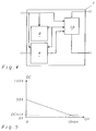
- the method according to the invention is characterized in that in a first step the auxiliary voltage in a digital signal is converted and this digital signal is then periodically transformed into a pulse-duration-modulated pulse train, the duty cycle of the pulse train becoming smaller as the auxiliary voltage increases.
- switchgear now has different auxiliary voltages from case to case, the monitoring devices must be adapted to the existing auxiliary voltage by hand and on site. Otherwise, different drive currents of the optocoupler would result for different voltages. So that this is not the case, the circuits in the prior art such as adjusted in the above-mentioned script using series resistors.
- the auxiliary voltage Uo is normally present when the switch is closed. This is divided in the voltage divider (R1, R2, C1) by a factor determined by the size of the resistors (R1, R2).
- the capacitor (C1) is used for voltage smoothing. This divided voltage is passed on to the signal converter.
- the pulse duration modulator (10) preferably controls the optocoupler in such a way that the optocoupler is switched on immediately after the switch is closed. Otherwise there would be a short delay.
Landscapes
- Engineering & Computer Science (AREA)
- Power Engineering (AREA)
- Arrangements For Transmission Of Measured Signals (AREA)
- Driving Mechanisms And Operating Circuits Of Arc-Extinguishing High-Tension Switches (AREA)
- Remote Monitoring And Control Of Power-Distribution Networks (AREA)
- Selective Calling Equipment (AREA)
- Maintenance And Inspection Apparatuses For Elevators (AREA)
- Dc-Dc Converters (AREA)
- Push-Button Switches (AREA)
- Alarm Systems (AREA)
- Measurement Of Length, Angles, Or The Like Using Electric Or Magnetic Means (AREA)
Applications Claiming Priority (2)
| Application Number | Priority Date | Filing Date | Title |
|---|---|---|---|
| DE4318189A DE4318189A1 (de) | 1993-06-01 | 1993-06-01 | Vorrichtung und Verfahren zur Überwachung einer Schalterstellung |
| DE4318189 | 1993-06-01 |
Publications (3)
| Publication Number | Publication Date |
|---|---|
| EP0631360A2 true EP0631360A2 (fr) | 1994-12-28 |
| EP0631360A3 EP0631360A3 (fr) | 1995-08-30 |
| EP0631360B1 EP0631360B1 (fr) | 1997-12-03 |
Family
ID=6489375
Family Applications (1)
| Application Number | Title | Priority Date | Filing Date |
|---|---|---|---|
| EP94107345A Expired - Lifetime EP0631360B1 (fr) | 1993-06-01 | 1994-05-11 | Dispositif et procédé de surveillance de la position d'un commutateur |
Country Status (5)
| Country | Link |
|---|---|
| US (1) | US5585678A (fr) |
| EP (1) | EP0631360B1 (fr) |
| JP (1) | JP3519447B2 (fr) |
| AT (1) | ATE160908T1 (fr) |
| DE (2) | DE4318189A1 (fr) |
Families Citing this family (17)
| Publication number | Priority date | Publication date | Assignee | Title |
|---|---|---|---|---|
| DE4408631C2 (de) * | 1994-03-09 | 1996-11-14 | Siemens Ag | Einrichtung zur Funktionssicherheitsüberwachung von Leistungsschalteinrichtungen (Diagnosegerät) |
| US7774443B2 (en) | 1996-07-23 | 2010-08-10 | Server Technology, Inc. | Power-manager configuration upload and download method and system for network managers |
| US7171461B2 (en) * | 1996-07-23 | 2007-01-30 | Server Technology, Inc. | Network remote power management outlet strip |
| US5949974A (en) * | 1996-07-23 | 1999-09-07 | Ewing; Carrell W. | System for reading the status and for controlling the power supplies of appliances connected to computer networks |
| US7099934B1 (en) | 1996-07-23 | 2006-08-29 | Ewing Carrel W | Network-connecting power manager for remote appliances |
| US7043543B2 (en) * | 1996-07-23 | 2006-05-09 | Server Technology, Inc. | Vertical-mount electrical power distribution plugstrip |
| US6711613B1 (en) * | 1996-07-23 | 2004-03-23 | Server Technology, Inc. | Remote power control system |
| US5914664A (en) * | 1997-07-03 | 1999-06-22 | Allen-Bradley Company, Llc | Optically sensing auxiliary switch |
| US6025793A (en) * | 1998-03-27 | 2000-02-15 | Samson Ag | Input circuit of a field device |
| DE19846965A1 (de) * | 1998-10-12 | 2000-04-13 | Dieter Mayer | Leitungsüberwachung |
| EP1137024A1 (fr) * | 2000-03-24 | 2001-09-26 | ABB Power Automation AG | Evaluation de la position codeé d'un commutateur |
| EP1791239A1 (fr) * | 2005-11-25 | 2007-05-30 | ABB Technology AG | Dispositif pour la transmission de la position d'un commutateur |
| DE102009034364B4 (de) * | 2009-07-20 | 2024-01-04 | Siemens Aktiengesellschaft | Einrichtung zur Ermittlung und Bewertung von analogen zeitabhängigen elektrischen Messsignalen |
| US8624601B2 (en) | 2010-10-04 | 2014-01-07 | Enerdel, Inc. | System and method for determining physical status of switch elements |
| US8766490B2 (en) | 2011-03-25 | 2014-07-01 | Enerdel, Inc. | System and method for monitoring operation of switch elements |
| US9703342B2 (en) | 2012-02-10 | 2017-07-11 | Server Technology, Inc. | System and method for configuring plurality of linked power distribution units in which configuration data of the linked power distribution units are accessible by the remote system |
| US10862298B2 (en) * | 2018-04-11 | 2020-12-08 | Schweitzer Engineering Laboratories, Inc. | Duty cycle modulated universal binary input circuit with reinforced isolation |
Family Cites Families (14)
| Publication number | Priority date | Publication date | Assignee | Title |
|---|---|---|---|---|
| CH480752A (de) * | 1968-03-26 | 1969-10-31 | Bbc Brown Boveri & Cie | Einrichtung zur Schalterstellungsanzeige in elektrischen Schaltanlagen |
| SU500565A1 (ru) * | 1973-12-11 | 1976-01-25 | Ордена Трудового Красного Знамени Институт Горного Дела Им.А.А.Скочинского | Устройство контрол нагрузки энергосистемы |
| SU758388A1 (ru) * | 1978-11-28 | 1980-08-23 | Tselinograd Selskokhoz I | Устройство контроля аварийных отключений секционирующих аппаратов 1 |
| DE3001940C2 (de) * | 1980-01-21 | 1983-01-27 | Siemens AG, 1000 Berlin und 8000 München | Anordnung zur Ermittlung der Schaltstellung eines Schalters und zur Überwachung der zugehörigen Leitung auf Kurzschluß und Unterbrechung |
| DE3108264C2 (de) | 1981-03-05 | 1984-05-30 | Deutsche Fernsprecher Gesellschaft Mbh Marburg, 3550 Marburg | Schaltungsanordnung zur Erkennung des Schaltzustandes einer Erdtaste eines Fernsprechapparates |
| DE3312153A1 (de) * | 1983-04-02 | 1984-10-04 | Grundig E.M.V. Elektro-Mechanische Versuchsanstalt Max Grundig & Co KG, 8510 Fürth | Verfahren und schaltungsanordnung zur tastenabfrage |
| CH652845A5 (de) | 1984-05-04 | 1985-11-29 | Bbc Brown Boveri & Cie | Ueberwachungseinrichtung fuer den ausloesekreis eines elektrischen leistungsschalters. |
| JPH01166400U (fr) * | 1988-05-10 | 1989-11-21 | ||
| US4864285A (en) | 1988-05-11 | 1989-09-05 | O G & E | Method and apparatus for testing contacts to determine if opened or closed |
| WO1989012928A1 (fr) * | 1988-06-16 | 1989-12-28 | Robert Bosch Gmbh | Appareil servant a detecter l'etat de conduction de plusieurs commutateurs sur une seule ligne de transmission |
| US5136280A (en) | 1989-05-15 | 1992-08-04 | Teledyne Industries, Inc. | Switch status indicator and self tester |
| US5065101A (en) | 1990-03-07 | 1991-11-12 | Nec Electronics, Inc. | Mini-relay or reed relay tester |
| US5422564A (en) * | 1991-11-18 | 1995-06-06 | Etcon Corporation | Low-power portable circuit breaker(s) locator |
| US5338467A (en) * | 1993-03-03 | 1994-08-16 | Witco Corporation | Sulfonate grease improvement |
-
1993
- 1993-06-01 DE DE4318189A patent/DE4318189A1/de not_active Withdrawn
-
1994
- 1994-04-06 JP JP06866694A patent/JP3519447B2/ja not_active Expired - Fee Related
- 1994-04-08 US US08/224,875 patent/US5585678A/en not_active Expired - Lifetime
- 1994-05-11 AT AT94107345T patent/ATE160908T1/de active
- 1994-05-11 DE DE59404707T patent/DE59404707D1/de not_active Expired - Lifetime
- 1994-05-11 EP EP94107345A patent/EP0631360B1/fr not_active Expired - Lifetime
Also Published As
| Publication number | Publication date |
|---|---|
| JPH0715894A (ja) | 1995-01-17 |
| US5585678A (en) | 1996-12-17 |
| EP0631360A3 (fr) | 1995-08-30 |
| EP0631360B1 (fr) | 1997-12-03 |
| DE59404707D1 (de) | 1998-01-15 |
| JP3519447B2 (ja) | 2004-04-12 |
| ATE160908T1 (de) | 1997-12-15 |
| DE4318189A1 (de) | 1994-12-08 |
Similar Documents
| Publication | Publication Date | Title |
|---|---|---|
| EP0631360B1 (fr) | Dispositif et procédé de surveillance de la position d'un commutateur | |
| DE69618870T2 (de) | Treiberimpuls-Begrenzerschaltung | |
| EP0170932B1 (fr) | Circuit pour alimenter des charges électriques à travers un hacheur de régulation | |
| DE9409760U1 (de) | Schaltungsanordnung zur Ansteuerung eines Schützes | |
| DE2539344A1 (de) | Elektronischer wattstundenzaehler mit automatischem messbereichsucher | |
| EP0268930A1 (fr) | Montage avec un commutateur de puissance autoprotégé | |
| DE3204800A1 (de) | Leistungswechselrichter | |
| DE4108259C2 (fr) | ||
| EP1301985B1 (fr) | Procede de detection et/ou de limitation de courts-circuits d'un convertisseur a commutation et ledit convertisseur a commutation | |
| EP2398137A2 (fr) | Régulateur de tension alternative | |
| WO1998043334A1 (fr) | Fusible electronique | |
| DE2922219B2 (de) | Elektronischer Sensor-Ein/Aus-Schalter | |
| DE3882787T2 (de) | Stromfühler. | |
| DE3922286A1 (de) | Verfahren und einrichtung zum detektieren einer verminderung der eingangsspannung fuer eine stromversorgung | |
| DE3420327C2 (fr) | ||
| DE2115807A1 (de) | Erdschlußschutzeinrichtung fur elektrische Gerate mit in Stern ge schalteten Wicklungen | |
| EP2770641A2 (fr) | Dispositif d'exploitation de signaux d'entrée électriques | |
| DE19649304A1 (de) | Schaltanordnung zur potentialgetrennten Spannungs- und/oder Strommessung | |
| DE3134599C2 (de) | Verfahren und Schaltungsanordnung zur Regelung der Ausgangsspannung eines fremdgesteuerten Gleichspannungswandlers | |
| EP0179262A1 (fr) | Méthode de protection et circuit de protection | |
| DE19516614C1 (de) | Anordnung mit einem an ein elektrisches Energieversorgungsnetz angeschlossenen Leitungsabgang mit einem Leistungsschalter und mit mindestens einem Motor und mit einer Unterspannungs-Schutzanordnung | |
| EP0569883A2 (fr) | Constitution des circuits pour limitation du courant lors de la fermeture du circuit à ensemble électronique | |
| DE3635789A1 (de) | Schaltung zur feststellung einer abnormalen bedingung fuer einen sperrwandler | |
| EP0509343A2 (fr) | Méthode de fonctionnement d'un régulateur à découpage et son dispositif | |
| WO1998043266A1 (fr) | Mecanisme de commande electromagnetique |
Legal Events
| Date | Code | Title | Description |
|---|---|---|---|
| PUAI | Public reference made under article 153(3) epc to a published international application that has entered the european phase |
Free format text: ORIGINAL CODE: 0009012 |
|
| AK | Designated contracting states |
Kind code of ref document: A2 Designated state(s): AT CH DE FR GB LI SE |
|
| PUAL | Search report despatched |
Free format text: ORIGINAL CODE: 0009013 |
|
| AK | Designated contracting states |
Kind code of ref document: A3 Designated state(s): AT CH DE FR GB LI SE |
|
| 17P | Request for examination filed |
Effective date: 19960207 |
|
| RAP1 | Party data changed (applicant data changed or rights of an application transferred) |
Owner name: ASEA BROWN BOVERI AG |
|
| GRAG | Despatch of communication of intention to grant |
Free format text: ORIGINAL CODE: EPIDOS AGRA |
|
| 17Q | First examination report despatched |
Effective date: 19970220 |
|
| GRAG | Despatch of communication of intention to grant |
Free format text: ORIGINAL CODE: EPIDOS AGRA |
|
| GRAH | Despatch of communication of intention to grant a patent |
Free format text: ORIGINAL CODE: EPIDOS IGRA |
|
| GRAH | Despatch of communication of intention to grant a patent |
Free format text: ORIGINAL CODE: EPIDOS IGRA |
|
| GRAA | (expected) grant |
Free format text: ORIGINAL CODE: 0009210 |
|
| AK | Designated contracting states |
Kind code of ref document: B1 Designated state(s): AT CH DE FR GB LI SE |
|
| REF | Corresponds to: |
Ref document number: 160908 Country of ref document: AT Date of ref document: 19971215 Kind code of ref document: T |
|
| REG | Reference to a national code |
Ref country code: CH Ref legal event code: EP |
|
| REF | Corresponds to: |
Ref document number: 59404707 Country of ref document: DE Date of ref document: 19980115 |
|
| GBT | Gb: translation of ep patent filed (gb section 77(6)(a)/1977) |
Effective date: 19980225 |
|
| ET | Fr: translation filed | ||
| PLBE | No opposition filed within time limit |
Free format text: ORIGINAL CODE: 0009261 |
|
| STAA | Information on the status of an ep patent application or granted ep patent |
Free format text: STATUS: NO OPPOSITION FILED WITHIN TIME LIMIT |
|
| 26N | No opposition filed | ||
| REG | Reference to a national code |
Ref country code: GB Ref legal event code: IF02 |
|
| REG | Reference to a national code |
Ref country code: CH Ref legal event code: PFA Free format text: ASEA BROWN BOVERI AG TRANSFER- ABB SCHWEIZ HOLDING AG Ref country code: CH Ref legal event code: NV Representative=s name: ABB SCHWEIZ AG INTELLECTUAL PROPERTY (CH-LC/IP) |
|
| REG | Reference to a national code |
Ref country code: FR Ref legal event code: CD Ref country code: FR Ref legal event code: CA |
|
| REG | Reference to a national code |
Ref country code: CH Ref legal event code: PUE Owner name: ABB SCHWEIZ AG Free format text: ABB SCHWEIZ HOLDING AG#BROWN BOVERI STRASSE 6#5400 BADEN (CH) -TRANSFER TO- ABB SCHWEIZ AG#BROWN BOVERI STRASSE 6#5400 BADEN (CH) |
|
| REG | Reference to a national code |
Ref country code: GB Ref legal event code: 732E |
|
| REG | Reference to a national code |
Ref country code: FR Ref legal event code: TP |
|
| PGFP | Annual fee paid to national office [announced via postgrant information from national office to epo] |
Ref country code: CH Payment date: 20120523 Year of fee payment: 19 Ref country code: DE Payment date: 20120523 Year of fee payment: 19 |
|
| PGFP | Annual fee paid to national office [announced via postgrant information from national office to epo] |
Ref country code: FR Payment date: 20120601 Year of fee payment: 19 Ref country code: GB Payment date: 20120522 Year of fee payment: 19 Ref country code: SE Payment date: 20120522 Year of fee payment: 19 |
|
| PGFP | Annual fee paid to national office [announced via postgrant information from national office to epo] |
Ref country code: AT Payment date: 20120511 Year of fee payment: 19 |
|
| REG | Reference to a national code |
Ref country code: CH Ref legal event code: PL |
|
| REG | Reference to a national code |
Ref country code: SE Ref legal event code: EUG |
|
| REG | Reference to a national code |
Ref country code: AT Ref legal event code: MM01 Ref document number: 160908 Country of ref document: AT Kind code of ref document: T Effective date: 20130531 |
|
| GBPC | Gb: european patent ceased through non-payment of renewal fee |
Effective date: 20130511 |
|
| PG25 | Lapsed in a contracting state [announced via postgrant information from national office to epo] |
Ref country code: CH Free format text: LAPSE BECAUSE OF NON-PAYMENT OF DUE FEES Effective date: 20130531 Ref country code: LI Free format text: LAPSE BECAUSE OF NON-PAYMENT OF DUE FEES Effective date: 20130531 Ref country code: AT Free format text: LAPSE BECAUSE OF NON-PAYMENT OF DUE FEES Effective date: 20130531 Ref country code: DE Free format text: LAPSE BECAUSE OF NON-PAYMENT OF DUE FEES Effective date: 20131203 Ref country code: SE Free format text: LAPSE BECAUSE OF NON-PAYMENT OF DUE FEES Effective date: 20130512 |
|
| REG | Reference to a national code |
Ref country code: DE Ref legal event code: R119 Ref document number: 59404707 Country of ref document: DE Effective date: 20131203 |
|
| REG | Reference to a national code |
Ref country code: FR Ref legal event code: ST Effective date: 20140131 |
|
| PG25 | Lapsed in a contracting state [announced via postgrant information from national office to epo] |
Ref country code: GB Free format text: LAPSE BECAUSE OF NON-PAYMENT OF DUE FEES Effective date: 20130511 |
|
| PG25 | Lapsed in a contracting state [announced via postgrant information from national office to epo] |
Ref country code: FR Free format text: LAPSE BECAUSE OF NON-PAYMENT OF DUE FEES Effective date: 20130531 |