EP0631405A1 - WDM Zeitmultiplex-Schleifenübertragungssystem - Google Patents
WDM Zeitmultiplex-Schleifenübertragungssystem Download PDFInfo
- Publication number
- EP0631405A1 EP0631405A1 EP94401417A EP94401417A EP0631405A1 EP 0631405 A1 EP0631405 A1 EP 0631405A1 EP 94401417 A EP94401417 A EP 94401417A EP 94401417 A EP94401417 A EP 94401417A EP 0631405 A1 EP0631405 A1 EP 0631405A1
- Authority
- EP
- European Patent Office
- Prior art keywords
- data
- wavelength
- local
- loop
- loop according
- Prior art date
- Legal status (The legal status is an assumption and is not a legal conclusion. Google has not performed a legal analysis and makes no representation as to the accuracy of the status listed.)
- Granted
Links
Images


Classifications
-
- H—ELECTRICITY
- H04—ELECTRIC COMMUNICATION TECHNIQUE
- H04J—MULTIPLEX COMMUNICATION
- H04J14/00—Optical multiplex systems
- H04J14/02—Wavelength-division multiplex systems
- H04J14/0287—Protection in WDM systems
- H04J14/0289—Optical multiplex section protection
-
- H—ELECTRICITY
- H04—ELECTRIC COMMUNICATION TECHNIQUE
- H04J—MULTIPLEX COMMUNICATION
- H04J14/00—Optical multiplex systems
- H04J14/02—Wavelength-division multiplex systems
- H04J14/0201—Add-and-drop multiplexing
-
- H—ELECTRICITY
- H04—ELECTRIC COMMUNICATION TECHNIQUE
- H04J—MULTIPLEX COMMUNICATION
- H04J14/00—Optical multiplex systems
- H04J14/02—Wavelength-division multiplex systems
- H04J14/0201—Add-and-drop multiplexing
- H04J14/0202—Arrangements therefor
- H04J14/0206—Express channels arrangements
-
- H—ELECTRICITY
- H04—ELECTRIC COMMUNICATION TECHNIQUE
- H04J—MULTIPLEX COMMUNICATION
- H04J14/00—Optical multiplex systems
- H04J14/02—Wavelength-division multiplex systems
- H04J14/0227—Operation, administration, maintenance or provisioning [OAMP] of WDM networks, e.g. media access, routing or wavelength allocation
-
- H—ELECTRICITY
- H04—ELECTRIC COMMUNICATION TECHNIQUE
- H04J—MULTIPLEX COMMUNICATION
- H04J14/00—Optical multiplex systems
- H04J14/02—Wavelength-division multiplex systems
- H04J14/0227—Operation, administration, maintenance or provisioning [OAMP] of WDM networks, e.g. media access, routing or wavelength allocation
- H04J14/0241—Wavelength allocation for communications one-to-one, e.g. unicasting wavelengths
-
- H—ELECTRICITY
- H04—ELECTRIC COMMUNICATION TECHNIQUE
- H04J—MULTIPLEX COMMUNICATION
- H04J14/00—Optical multiplex systems
- H04J14/02—Wavelength-division multiplex systems
- H04J14/0278—WDM optical network architectures
- H04J14/0283—WDM ring architectures
-
- H—ELECTRICITY
- H04—ELECTRIC COMMUNICATION TECHNIQUE
- H04J—MULTIPLEX COMMUNICATION
- H04J14/00—Optical multiplex systems
- H04J14/08—Time-division multiplex systems
-
- H—ELECTRICITY
- H04—ELECTRIC COMMUNICATION TECHNIQUE
- H04J—MULTIPLEX COMMUNICATION
- H04J14/00—Optical multiplex systems
- H04J14/02—Wavelength-division multiplex systems
- H04J14/0201—Add-and-drop multiplexing
- H04J14/0202—Arrangements therefor
- H04J14/0204—Broadcast and select arrangements, e.g. with an optical splitter at the input before adding or dropping
-
- H—ELECTRICITY
- H04—ELECTRIC COMMUNICATION TECHNIQUE
- H04J—MULTIPLEX COMMUNICATION
- H04J14/00—Optical multiplex systems
- H04J14/02—Wavelength-division multiplex systems
- H04J14/0201—Add-and-drop multiplexing
- H04J14/0202—Arrangements therefor
- H04J14/0213—Groups of channels or wave bands arrangements
-
- H—ELECTRICITY
- H04—ELECTRIC COMMUNICATION TECHNIQUE
- H04J—MULTIPLEX COMMUNICATION
- H04J14/00—Optical multiplex systems
- H04J14/02—Wavelength-division multiplex systems
- H04J14/0278—WDM optical network architectures
- H04J14/0286—WDM hierarchical architectures
-
- H—ELECTRICITY
- H04—ELECTRIC COMMUNICATION TECHNIQUE
- H04J—MULTIPLEX COMMUNICATION
- H04J14/00—Optical multiplex systems
- H04J14/08—Time-division multiplex systems
- H04J14/083—Add and drop multiplexing
Definitions
- the present invention relates to a transmission loop with time and wavelength multiplexing. It finds an application in optical telecommunications.
- FIG. 1 Some transmission networks are organized in loops, as shown in Figure 1 attached. We can see a general network 10 and several loops B1, B2, etc ... Each loop is shown in more detail in Figure 2. It includes a BRX circuit called network head, which is a cross-connect, and several circuits MIE, which are insertion and extraction multiplexers. Each of these multiplexers is arranged in a local area to be served, ie Z1, Z2, Z3.
- a double link 12, 12 ′ carries the data between the headend and the multiplexers, in two different directions.
- Such loop networks are well suited to the new transmission technique called "synchronous digital hierarchy" or HNS for short (SDH in English, for “Synchronous Digital Hierarchy”).
- the headend also includes a BRX circuit coupled to the general network. It processes electrical data.
- a transmitter 20 constituted by several light sources (four in the example illustrated) delivering four optical beams at different wavelengths.
- a multiplexer 22 multiplexes these beams and introduces them into a single-mode optical fiber F0.
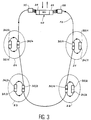
- Each zone Z1, Z2, Z3, Z4 comprises an insertion and extraction multiplexer consisting of an optical component 30/1, 30/2, 30/3, 30/4 of the coupler type, this component being capable of extracting one or more wavelengths to address them to a receiver 32/1, 32/2, 32/3, 32/4.
- transmitters 34/1, 34/2, 34/3, 34/4 arranged in the local areas and the component 30/1, 30/2, 30/3, 30 / 4 and makes it possible to insert into the beam circulating on the optical fiber F0, data coming from each local area, instead of the extracted data.
- the loop closes on the network head 40 by a demultiplexer 35, which separates the different beams of different wavelengths and a receiver 37, which delivers the data in electrical form and addresses them to the BRX mixer.
- a second backup optical fiber can be added to form, with the appropriate optical components (coupler, receiver, transmitter), a backup loop, which can work in the opposite direction to the main loop.
- the extraction and insertion means are diffraction gratings capable of extracting five wavelengths out of 30.
- the wavelengths range between 1538 and 1566 nm, every 2 nanometers (or about thirty nanometers for 15 channels).
- Each diffraction grating is capable of extracting five wavelengths from the set.
- the network extracts the wavelengths at 1558, 1560, 1562, 1564 and 1566 nm.
- the object of the present invention is precisely to remedy these drawbacks.
- the network head comprises a single semiconductor laser but which is tunable in wavelength.
- This laser is wavelength controlled to assign different wavelengths to various data groups. For each group, the light beam (emitted at the particular wavelength) is modulated by the group's data. One thus obtains, at the output of the laser, a multicolored sequence of groups of data.
- Each local area is then assigned a specific wavelength.
- the multiplexer of each local area comprises means for extracting from the multicolored sequence it receives, the group which has the wavelength specific to its area. The data intended for this zone are therefore delivered to him.
- the multiplexer in each local area also includes a single wavelength tunable semiconductor laser for inserting data from the local area into the multicolored sequence, replacing the group that has been extracted.
- the wavelength used for the inserted data can be either the wavelength specific to the local area, or a different wavelength, but which is the same for all stations.
- the loop closes on the network head by means capable of recovering the data contained in the multicolored sequence coming to the head and to transfer this data on the general network.
- the lasers which are very suitable for the invention are semiconductor lasers of the DFB or DBR multielectrode type. Such lasers are known and described, for example, in the article by M.J. CHAWKI et al. entitled “M3NET Demonstration of HD WDM Optical Network Using Two Electrode DFB Laser Filter as Tunable Narrow-band FM Receiver”, published in "Electronics Letters", vol. 28, n ° 2, 1992, pp. 147-148.
- tunable lasers have two main advantages: the switching speed as well as a continuous tuning range of the emission wavelength.
- the best result obtained by the inventors concerned a distributed feedback laser with a length of 200 ⁇ m and with two electrodes.
- the 1.5 ⁇ m tuning range was 200 GHz (about 1.5 nm); the line width was 25 MHz maximum.
- a switching time of 550 ps was measured in a mode switching experiment.
- tunable sources allow dense multiplexing with a distance between channels which is typically 0.3 to 0.5 nm.
- the spectral range used is then less than 2 nm for 4 channels whereas it was more than 8 nm in the prior art.
- the semiconductor laser control means may also be able to control the transmission of synchronization signals accompanying the data, each synchronization signal intended for a local area being transmitted throughout wave specific to this area.
- the set of synchronization signals intended for all the local areas of the loop can form a byte.
- the data groups are also bytes.
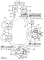
- the network head 40 includes a BRX cross-connect connected to the general network 10, this cross-connect delivering electrical signals organized for example according to the so-called STM 4 frame (the abbreviation STM meaning "Synchronous Transport Module”).
- STM Synchronous Transport Module
- the speed can be 622,080 kbits / s.
- a demultiplexer 41 divides this data stream into four STM 1 frames of 155,520 bits / s each.
- a multiplexer 42 organizes this data into time multiplexed groups, in this case into 4 groups G1, G2, G3, G4 intended respectively for the four zones Z1, Z2, Z3, Z4. Each of these groups can be a byte. These groups appear on the output 43 of the multiplexer 42.
- This multiplexer also produces, on a second output 45, four control signals SC1, SC2, SC3, SC4 in synchronism with the data groups.
- the emitter stage of the headend 40 also comprises a bielectrode semiconductor laser 46, one electrode E1 of which receives the data groups G1, G2, G3, G4 and the other electrode E2 the control signals SC1, SC2, SC3 , SC4.
- the latter control the emission wavelength of the laser and the former modulate the emission of the laser (in amplitude or frequency).
- the laser 46 there is therefore a multicolored light beam in the sense that it comprises a sequence of signals at different lengths ⁇ 1 , ⁇ 2 , ⁇ 3 , ⁇ 4 , each signal carrying, by its modulation, the data from groups G1, G2, G3, G4.
- This multicolored sequence is referenced Seq and includes groups L1, L2, L3, L4 at wavelengths ⁇ 1 , ⁇ 2 , ⁇ 3 , ⁇ 4.
- each group of data is associated with a time position and a spectral position.
- the circuit 42 also produces a synchronization signal, formed for example by two bits 1 and 0 for each group of data. This signal is converted to the wavelength corresponding to the group.
- the data sequence is then preceded by a synchronization group Ls formed by four wavelengths ⁇ 1 , ⁇ 2 , ⁇ 3 , ⁇ 4 , each modulated by 1 and 0. All of the synchronization signal Ls and four groups of data L1, L2, L3, L4 form the sequence Seq.
- each group of data is separated from the next by a bit, for example 0.
- This solution is essential for high speed transmission, for example STM 16.
- This sequence propagates in the single-mode optical fiber F0 and serves the four local stations Z1, Z2, Z3, Z4.
- a passive optical component C1 of the coupler type, which takes the part of the incident multicolored sequence which is at the wavelength ⁇ 1, that is to say at both the synchronization signal and the data.
- an optical filter F1 centered on this wavelength, and a photodetector D1.
- a processing circuit CT1 is connected to the detector and delivers the data group G1 organized in the form of a frame STM 1.
- the processing circuit CT1 also receives data G 1 from the local area Z1 and sends it to a tunable laser source S1.
- the synchronization signal at the wavelength ⁇ 1, which was taken by the coupler C1, is used to form a control signal from the source S1 at the wavelength ⁇ 1.
- the light signal generated by the source S1 is directed in component C1, so that the data group G 1 will be automatically inserted in the location freed by the extraction.
- the multicolored sequence leaving the local area Z1 then comprises, after the synchronization group Ls, a group L 1 (the high index indicating an inserted group) plus the original groups L2, L3, L4.
- the local zone Z2 extracts the group L2 and reinserts the group L 2.
- the network head 40 furthermore comprises, at the other end of the loop, reception means constituted by an optical coupler 50, four filters F1, F2, F3, F4 centered respectively on the wavelengths ⁇ 1 , ⁇ 2 , ⁇ 3 , ⁇ 4 , four photodetectors D1, D2, D3, D4, a demultiplexer 52 which organizes the data delivered by the photodetectors into four STM frames 1, a multiplexer 54 which reconstitutes an STM frame 4 and finally the BRX cross-connect which reinserts the data of the loop into the general network 10.
- reception means constituted by an optical coupler 50, four filters F1, F2, F3, F4 centered respectively on the wavelengths ⁇ 1 , ⁇ 2 , ⁇ 3 , ⁇ 4 , four photodetectors D1, D2, D3, D4, a demultiplexer 52 which organizes the data delivered by the photodetectors into four STM frames 1, a multiplexer 54 which reconstitutes an STM frame 4 and finally the BR
- the laser sources S1, S2, S3, S4 arranged in each local area do not emit at the wavelength specific to the area, that is to say at ⁇ 1 , ⁇ 2 , ⁇ 3 , ⁇ 4 , but at a single wavelength ⁇ 0 , which is the same for all the zones.
- the network head is thereby simplified, on the reception side, a single filter F0 centered on ⁇ 0 and a single photodetector D0 are sufficient. We then find the demultiplexer 52 and the multiplexer 54.
- the invention also covers the case of a loop which would serve three local areas with an STM 4 tributary; there is then an additional STM 1 signal which can be assigned to the local area which needs it.
- the insertion function works as before, but the extraction function will see two bytes arriving in a single sequence which will be differentiated and processed on two channels in parallel to reconstruct two STM 1 signals.
- Another synchronization solution can consist in starting the data sequence by a few binary elements transmitted under another wavelength. ⁇ 5 . This implies the detection of this wavelength by all the local areas of the loop.
- the quantity ⁇ l represents the weakening of the optical fiber between two local areas.
- the following table presents the link budget for each wavelength ⁇ 1, ⁇ 2, ⁇ 3, of a loop with 3 local zones.
- the extraction path corresponds to the part of the loop located between the head of the network and the station considered, for example the local zone Z1 for ⁇ 1 .
- the insertion path corresponds to the part of the loop located between the local zone Z1 for ⁇ 1 (Z2 for ⁇ 2 , ...) and the reception at the end of the loop.
- the couplers are assumed to be symmetrical.
- the attenuations are respectively: ⁇ 1 ⁇ 2 ⁇ 3 extraction route ⁇ l + 10 dB 2 ⁇ l + 15.5 dB 3 ⁇ l + 21 dB insertion route 3 ⁇ l + 26.5 dB 2 ⁇ l + 21dB ⁇ l + 15.5 dB
- the highest attenuation is 26.5 dB + 3 ⁇ l.
- a detection threshold of -34 dBm at 620 Mbits / s we obtain a loop length of 13 km if we transmit at -5 dBm and 40 km if we transmit at 0 dBm.
- Attenuation at the receiver ⁇ 1 ⁇ 2 ⁇ 3 ⁇ 4 extraction route ⁇ l + 10 dB 2 ⁇ l + 15.5 dB 3 ⁇ l + 21 dB 4 ⁇ l + 26.5 dB insertion route 4 ⁇ l + 33.5 dB 3 ⁇ l + 28 dB 2 ⁇ l + 22.5 dB ⁇ l + 17dB
- the maximum attenuation is 33.5 dB + 4 ⁇ l.
- the loop size is 2.5 km for a 0 dBm emission and 42.5 km for a 10 dBm emission.
- the highest attenuation is 21 dB + 3 ⁇ l; the loop size is (detection threshold -34 dBm at 620 Mbit / s) of 42.6 km respectively for a transmission at -5 dBm and 69 km for a transmission at 0 dBm.
- the maximum attenuation is 26.5 dB + 4 ⁇ l; which results in a loop size of 12.5 km for a transmission at -5 dBm, 37.5 km for a transmission at 0 dBm and 77.5 km for a transmission at +10 dBm.
- An additional function can be implemented in this configuration, namely the exchange of information between a local area i and a local area j during the rest periods common to the two areas. Indeed, outside the active period ti, the source of the area i is at rest; outside the period tj, the reception circuit of the zone j is at rest (except for overhead as envisaged previously).
- the source of the zone i can then transmit, for a period different from ti and tj, a byte (therefore an STM stream 1) to the zone j; it must ensure that there is no overhead and signal to the head of the network that this period is occupied by the zone j in reception.
- the invention is not limited to the case where the network head is constituted by a single entity.
- the invention covers the case of a loop where the network head is provided by two entities remote, a sending entity and a receiving entity. The local areas are distributed along the optical fiber between these two entities.
- the loop is sort of open.
Landscapes
- Engineering & Computer Science (AREA)
- Computer Networks & Wireless Communication (AREA)
- Signal Processing (AREA)
- Optical Communication System (AREA)
- Small-Scale Networks (AREA)
Applications Claiming Priority (2)
| Application Number | Priority Date | Filing Date | Title |
|---|---|---|---|
| FR9307764A FR2707065B1 (de) | 1993-06-25 | 1993-06-25 | |
| FR9307764 | 1993-06-25 |
Publications (2)
| Publication Number | Publication Date |
|---|---|
| EP0631405A1 true EP0631405A1 (de) | 1994-12-28 |
| EP0631405B1 EP0631405B1 (de) | 2002-11-13 |
Family
ID=9448564
Family Applications (1)
| Application Number | Title | Priority Date | Filing Date |
|---|---|---|---|
| EP19940401417 Expired - Lifetime EP0631405B1 (de) | 1993-06-25 | 1994-06-23 | WDM Zeitmultiplex-Schleifenübertragungssystem |
Country Status (3)
| Country | Link |
|---|---|
| EP (1) | EP0631405B1 (de) |
| DE (1) | DE69431694T2 (de) |
| FR (1) | FR2707065B1 (de) |
Cited By (7)
| Publication number | Priority date | Publication date | Assignee | Title |
|---|---|---|---|---|
| FR2734953A1 (fr) * | 1995-05-29 | 1996-12-06 | France Telecom | Dispositif de commutation de frequences d'emission d'une source lumineuse |
| WO1997036403A1 (en) * | 1996-03-25 | 1997-10-02 | Net Insight Ab | Bitstream management |
| US6978090B1 (en) * | 2000-07-31 | 2005-12-20 | Nortel Networks Limited | Optical network architecture |
| EP1564922A3 (de) * | 2004-02-17 | 2006-05-17 | Fujitsu Limited | Verfahren zum Empfangen und Senden für ein optisches Ringnetzwerk und entsprechender Netzwerkknoten |
| EP1566910A3 (de) * | 2004-02-19 | 2006-12-13 | Fujitsu Limited | Optisches Datennetzwerk |
| US7603035B2 (en) | 2004-09-03 | 2009-10-13 | Fujitsu Limited | Method and system for a data centric architecture in an optical network |
| EP2339770A1 (de) * | 2002-05-29 | 2011-06-29 | Fujitsu Limited | Optisches Ringnetzwerk mit Knoten und Verfahren |
Citations (2)
| Publication number | Priority date | Publication date | Assignee | Title |
|---|---|---|---|---|
| EP0295857A1 (de) * | 1987-06-12 | 1988-12-21 | BRITISH TELECOMMUNICATIONS public limited company | Optische Multiplexierung |
| EP0520494A2 (de) * | 1991-06-27 | 1992-12-30 | Nec Corporation | Nachrichtenübertragungssystem mit Wellenlängenmultiplexierung |
-
1993
- 1993-06-25 FR FR9307764A patent/FR2707065B1/fr not_active Expired - Fee Related
-
1994
- 1994-06-23 DE DE1994631694 patent/DE69431694T2/de not_active Expired - Fee Related
- 1994-06-23 EP EP19940401417 patent/EP0631405B1/de not_active Expired - Lifetime
Patent Citations (2)
| Publication number | Priority date | Publication date | Assignee | Title |
|---|---|---|---|---|
| EP0295857A1 (de) * | 1987-06-12 | 1988-12-21 | BRITISH TELECOMMUNICATIONS public limited company | Optische Multiplexierung |
| EP0520494A2 (de) * | 1991-06-27 | 1992-12-30 | Nec Corporation | Nachrichtenübertragungssystem mit Wellenlängenmultiplexierung |
Non-Patent Citations (3)
| Title |
|---|
| D.J. PRAT ET AL.: "Four channel multiple wavelength laser transmitter module for 1550 nm WDM system.", ELECTRONICS LETTERS., vol. 28, no. 11, 21 May 1992 (1992-05-21), STEVENAGE GB, pages 1066 - 1067, XP000318934 * |
| N. TAT ET AL.: "ATM technology development in RACE.", PROCEEDINGS IEEE GLOBAL TELECOMMUNICATIONS CONFERENCE., vol. 2, 2 December 1991 (1991-12-02), PHOENIX (US), pages 1506 - 1514, XP000332900 * |
| STUART S. WAGNER ET AL.: "Multiwavelength ring networks for switch consolidation and interconnection.", SUPERCOM '92;PROCEEDINGS INTERNATIONAL CONFERENCE ON COMMUNICATIONS, vol. 3, 14 June 1992 (1992-06-14), CHICAGO (US), pages 1173 - 1179 * |
Cited By (7)
| Publication number | Priority date | Publication date | Assignee | Title |
|---|---|---|---|---|
| FR2734953A1 (fr) * | 1995-05-29 | 1996-12-06 | France Telecom | Dispositif de commutation de frequences d'emission d'une source lumineuse |
| WO1997036403A1 (en) * | 1996-03-25 | 1997-10-02 | Net Insight Ab | Bitstream management |
| US6978090B1 (en) * | 2000-07-31 | 2005-12-20 | Nortel Networks Limited | Optical network architecture |
| EP2339770A1 (de) * | 2002-05-29 | 2011-06-29 | Fujitsu Limited | Optisches Ringnetzwerk mit Knoten und Verfahren |
| EP1564922A3 (de) * | 2004-02-17 | 2006-05-17 | Fujitsu Limited | Verfahren zum Empfangen und Senden für ein optisches Ringnetzwerk und entsprechender Netzwerkknoten |
| EP1566910A3 (de) * | 2004-02-19 | 2006-12-13 | Fujitsu Limited | Optisches Datennetzwerk |
| US7603035B2 (en) | 2004-09-03 | 2009-10-13 | Fujitsu Limited | Method and system for a data centric architecture in an optical network |
Also Published As
| Publication number | Publication date |
|---|---|
| DE69431694D1 (de) | 2002-12-19 |
| FR2707065A1 (de) | 1994-12-30 |
| DE69431694T2 (de) | 2003-07-17 |
| FR2707065B1 (de) | 1995-07-21 |
| EP0631405B1 (de) | 2002-11-13 |
Similar Documents
| Publication | Publication Date | Title |
|---|---|---|
| EP0677936B1 (de) | Wiederkonfigurierbares optisches Mehrwellenlängen-Ringnetzwerk | |
| CA2026658C (fr) | Systeme de communication optique temporel asynchrone | |
| US6826368B1 (en) | Wavelength division multiplexing (WDM) with multi-frequency lasers and optical couplers | |
| EP0792038B1 (de) | Überwachungssystem eines Multiwellenlängen-Ringnetzes | |
| FR2738432A1 (fr) | Composant optique adapte a la surveillance d'une liaison multilongueur d'onde et multiplexeur a insertion-extraction utilisant ce composant, application aux reseaux optiques | |
| EP0682424A1 (de) | Verfahren zur gemeinsamen Informationsbenutzung zwischen einer Vielzahl von Knoten in einem Übertragungsnetz | |
| EP0838918B1 (de) | Vorrichtung zum Ein-und Ausfügen von Wellenlängenmultiplexkanälen | |
| FR2696891A1 (fr) | Matrice de commutation optique. | |
| EP0734131B1 (de) | Verfahren zur Verwaltung eines optischen Ringes mit Wellenlängenmultiplex | |
| EP0631405B1 (de) | WDM Zeitmultiplex-Schleifenübertragungssystem | |
| EP0812077B1 (de) | Endgerät für eine gesicherte bidirektionale, nach der synchronen digitalen Hierarchie multiplexierte Daten übermittelnde Verbindung | |
| EP0568402A1 (de) | Fernmeldenetz | |
| EP1788736B1 (de) | Verbesserte Datenübertragungsvorrichtung zur Kommunikationseinrichtungen in einem passiven optischen Netzwerk | |
| US7856182B2 (en) | Optical CWDM-system | |
| EP0697800B1 (de) | Optische Rangierverteiler | |
| EP0568447A1 (de) | Multiplexer zum Einfügen und Extrahieren | |
| Perrier et al. | Wavelength‐division integration of services in fibre‐optic networks | |
| FR2736480A1 (fr) | Disposif de coloration de signaux optiques | |
| FR2829327A1 (fr) | Reseau en anneau realise a partir d'un bus optique double | |
| EP1762030A1 (de) | Privates mehrdienstnetz und schnittstellenmodule für den datentransport in verschiedenen formaten in einem derartigen netz | |
| EP1193995A1 (de) | Koppelfeld für ein optischen WDM Netzwerk | |
| FR2821504A1 (fr) | Dispositif d'extraction de frequence | |
| EP1213866A1 (de) | Verschachtelte Banden Demultiplex-Multiplex-System | |
| FR2756442A1 (fr) | Reseau en anneau multilongueur d'onde pour le raccordement d'usagers, notamment d'usagers professionnels | |
| FR2682240A1 (fr) | Systeme de raccordement optique de terminaux d'abonnes a un centre local d'un reseau de telecommunications. |
Legal Events
| Date | Code | Title | Description |
|---|---|---|---|
| PUAI | Public reference made under article 153(3) epc to a published international application that has entered the european phase |
Free format text: ORIGINAL CODE: 0009012 |
|
| AK | Designated contracting states |
Kind code of ref document: A1 Designated state(s): DE GB |
|
| 17P | Request for examination filed |
Effective date: 19950602 |
|
| 17Q | First examination report despatched |
Effective date: 19991206 |
|
| GRAG | Despatch of communication of intention to grant |
Free format text: ORIGINAL CODE: EPIDOS AGRA |
|
| GRAG | Despatch of communication of intention to grant |
Free format text: ORIGINAL CODE: EPIDOS AGRA |
|
| GRAH | Despatch of communication of intention to grant a patent |
Free format text: ORIGINAL CODE: EPIDOS IGRA |
|
| GRAH | Despatch of communication of intention to grant a patent |
Free format text: ORIGINAL CODE: EPIDOS IGRA |
|
| GRAA | (expected) grant |
Free format text: ORIGINAL CODE: 0009210 |
|
| AK | Designated contracting states |
Kind code of ref document: B1 Designated state(s): DE GB |
|
| REG | Reference to a national code |
Ref country code: GB Ref legal event code: FG4D Free format text: NOT ENGLISH |
|
| REF | Corresponds to: |
Ref document number: 69431694 Country of ref document: DE Date of ref document: 20021219 |
|
| GBT | Gb: translation of ep patent filed (gb section 77(6)(a)/1977) |
Effective date: 20030311 |
|
| PLBE | No opposition filed within time limit |
Free format text: ORIGINAL CODE: 0009261 |
|
| STAA | Information on the status of an ep patent application or granted ep patent |
Free format text: STATUS: NO OPPOSITION FILED WITHIN TIME LIMIT |
|
| 26N | No opposition filed |
Effective date: 20030814 |
|
| PGFP | Annual fee paid to national office [announced via postgrant information from national office to epo] |
Ref country code: GB Payment date: 20060530 Year of fee payment: 13 |
|
| PGFP | Annual fee paid to national office [announced via postgrant information from national office to epo] |
Ref country code: DE Payment date: 20060608 Year of fee payment: 13 |
|
| GBPC | Gb: european patent ceased through non-payment of renewal fee |
Effective date: 20070623 |
|
| PG25 | Lapsed in a contracting state [announced via postgrant information from national office to epo] |
Ref country code: DE Free format text: LAPSE BECAUSE OF NON-PAYMENT OF DUE FEES Effective date: 20080101 |
|
| PG25 | Lapsed in a contracting state [announced via postgrant information from national office to epo] |
Ref country code: GB Free format text: LAPSE BECAUSE OF NON-PAYMENT OF DUE FEES Effective date: 20070623 |