EP0631491B1 - Dispostif permettant de localiser et de ponctionner des vaisseaux sanguins - Google Patents
Dispostif permettant de localiser et de ponctionner des vaisseaux sanguins Download PDFInfo
- Publication number
- EP0631491B1 EP0631491B1 EP94903716A EP94903716A EP0631491B1 EP 0631491 B1 EP0631491 B1 EP 0631491B1 EP 94903716 A EP94903716 A EP 94903716A EP 94903716 A EP94903716 A EP 94903716A EP 0631491 B1 EP0631491 B1 EP 0631491B1
- Authority
- EP
- European Patent Office
- Prior art keywords
- probe
- sterile
- cap
- guiding tube
- ultrasonic
- Prior art date
- Legal status (The legal status is an assumption and is not a legal conclusion. Google has not performed a legal analysis and makes no representation as to the accuracy of the status listed.)
- Expired - Lifetime
Links
- 210000004204 blood vessel Anatomy 0.000 title claims abstract description 5
- 239000000523 sample Substances 0.000 claims abstract description 70
- 230000008878 coupling Effects 0.000 abstract description 13
- 238000010168 coupling process Methods 0.000 abstract description 13
- 238000005859 coupling reaction Methods 0.000 abstract description 13
- 230000000149 penetrating effect Effects 0.000 abstract 1
- 238000002604 ultrasonography Methods 0.000 description 54
- 238000004806 packaging method and process Methods 0.000 description 28
- 239000000499 gel Substances 0.000 description 10
- 229920003023 plastic Polymers 0.000 description 9
- 239000004033 plastic Substances 0.000 description 9
- 230000003287 optical effect Effects 0.000 description 7
- 238000009459 flexible packaging Methods 0.000 description 6
- 239000000463 material Substances 0.000 description 5
- XLYOFNOQVPJJNP-UHFFFAOYSA-N water Substances O XLYOFNOQVPJJNP-UHFFFAOYSA-N 0.000 description 5
- 238000011109 contamination Methods 0.000 description 3
- 238000003384 imaging method Methods 0.000 description 3
- 238000004519 manufacturing process Methods 0.000 description 3
- 238000000034 method Methods 0.000 description 3
- 238000010521 absorption reaction Methods 0.000 description 2
- 210000001367 artery Anatomy 0.000 description 2
- 239000008280 blood Substances 0.000 description 2
- 210000004369 blood Anatomy 0.000 description 2
- 239000007787 solid Substances 0.000 description 2
- 238000003860 storage Methods 0.000 description 2
- 210000003462 vein Anatomy 0.000 description 2
- JOYRKODLDBILNP-UHFFFAOYSA-N Ethyl urethane Chemical compound CCOC(N)=O JOYRKODLDBILNP-UHFFFAOYSA-N 0.000 description 1
- VVQNEPGJFQJSBK-UHFFFAOYSA-N Methyl methacrylate Chemical compound COC(=O)C(C)=C VVQNEPGJFQJSBK-UHFFFAOYSA-N 0.000 description 1
- 229920005372 Plexiglas® Polymers 0.000 description 1
- FAPWRFPIFSIZLT-UHFFFAOYSA-M Sodium chloride Chemical compound [Na+].[Cl-] FAPWRFPIFSIZLT-UHFFFAOYSA-M 0.000 description 1
- 229920006311 Urethane elastomer Polymers 0.000 description 1
- 239000000853 adhesive Substances 0.000 description 1
- 230000001070 adhesive effect Effects 0.000 description 1
- 230000017531 blood circulation Effects 0.000 description 1
- 239000013078 crystal Substances 0.000 description 1
- 238000005520 cutting process Methods 0.000 description 1
- 238000013016 damping Methods 0.000 description 1
- 229940079593 drug Drugs 0.000 description 1
- 239000003814 drug Substances 0.000 description 1
- 230000000694 effects Effects 0.000 description 1
- 229920001971 elastomer Polymers 0.000 description 1
- 239000000806 elastomer Substances 0.000 description 1
- 230000004807 localization Effects 0.000 description 1
- 239000012528 membrane Substances 0.000 description 1
- PUZPDOWCWNUUKD-UHFFFAOYSA-M sodium fluoride Chemical compound [F-].[Na+] PUZPDOWCWNUUKD-UHFFFAOYSA-M 0.000 description 1
Images


Classifications
-
- A—HUMAN NECESSITIES
- A61—MEDICAL OR VETERINARY SCIENCE; HYGIENE
- A61B—DIAGNOSIS; SURGERY; IDENTIFICATION
- A61B8/00—Diagnosis using ultrasonic, sonic or infrasonic waves
- A61B8/42—Details of probe positioning or probe attachment to the patient
- A61B8/4272—Details of probe positioning or probe attachment to the patient involving the acoustic interface between the transducer and the tissue
- A61B8/4281—Details of probe positioning or probe attachment to the patient involving the acoustic interface between the transducer and the tissue characterised by sound-transmitting media or devices for coupling the transducer to the tissue
-
- A—HUMAN NECESSITIES
- A61—MEDICAL OR VETERINARY SCIENCE; HYGIENE
- A61B—DIAGNOSIS; SURGERY; IDENTIFICATION
- A61B1/00—Instruments for performing medical examinations of the interior of cavities or tubes of the body by visual or photographical inspection, e.g. endoscopes; Illuminating arrangements therefor
- A61B1/00142—Instruments for performing medical examinations of the interior of cavities or tubes of the body by visual or photographical inspection, e.g. endoscopes; Illuminating arrangements therefor with means for preventing contamination, e.g. by using a sanitary sheath
-
- A—HUMAN NECESSITIES
- A61—MEDICAL OR VETERINARY SCIENCE; HYGIENE
- A61B—DIAGNOSIS; SURGERY; IDENTIFICATION
- A61B8/00—Diagnosis using ultrasonic, sonic or infrasonic waves
- A61B8/08—Clinical applications
- A61B8/0833—Clinical applications involving detecting or locating foreign bodies or organic structures
- A61B8/0841—Clinical applications involving detecting or locating foreign bodies or organic structures for locating instruments
-
- A—HUMAN NECESSITIES
- A61—MEDICAL OR VETERINARY SCIENCE; HYGIENE
- A61B—DIAGNOSIS; SURGERY; IDENTIFICATION
- A61B8/00—Diagnosis using ultrasonic, sonic or infrasonic waves
- A61B8/44—Constructional features of the ultrasonic, sonic or infrasonic diagnostic device
- A61B8/4422—Constructional features of the ultrasonic, sonic or infrasonic diagnostic device related to hygiene or sterilisation
-
- A—HUMAN NECESSITIES
- A61—MEDICAL OR VETERINARY SCIENCE; HYGIENE
- A61B—DIAGNOSIS; SURGERY; IDENTIFICATION
- A61B5/00—Measuring for diagnostic purposes; Identification of persons
- A61B5/48—Other medical applications
- A61B5/4887—Locating particular structures in or on the body
- A61B5/489—Blood vessels
Definitions
- the object of the invention relates to a Apparatus according to claim 1, which with an ultrasonic Doppler device and Puncturing needle in one sterile area a non-invasive location and puncture of blood vessels allowed.
- the ultrasound Doppler device is not sterile and for repeated use Applications are provided and is helped before each use sterile packaging.
- a sterile coupling piece can be attached over the sterile cover, which leads the puncturing needle into the ultrasound cutting plane so that the Puncturing needle is visible on the screen (such as in US-4,898,178 is described).
- imaging devices cannot be sterilized and so big that they can hardly be packed sterile and therefore one need their own storage space outside the sterile operating field.
- a The ultrasonic probe then connects at least two meters of electrical cable with the electronic housing, what in the narrow spatial Ratios of intensive care units or catheterization rooms is disadvantageous.
- ultrasonic Doppler devices which are only acoustic Play signals and can therefore be much smaller and cheaper than the imaging.
- Puncturing needle almost identical to the axis of the ultrasound field.
- the piezo crystals of the ultrasound probe and the puncture needle are spatially located so close together that contamination of the ultrasound probe by the Patient blood is made.
- Contamination also occurs when the ultrasound probe is used is arranged around the needle, e.g. in CH-501'410.
- the Contaminated ultrasound probes can be gas sterilized, but this one The process is time-consuming and also shortens the lifespan of the expensive ones Ultrasound probes significantly. It is also expensive to replace the ultrasound probe once Throw away use, as some manufacturers recommend.
- EP-0'516'582 A1 describes a device in which a non-sterile ultrasound probe can be used because it does not have the Puncture the needle, the doctor's gloves and the patient's skin can. This is because a sterile is placed on the non-sterile ultrasound probe Coupling piece plugged in, with the help of a mirror, the ultrasonic field is deflected such that the puncturing needle, which is also through the coupling piece is guided, parallel to and in the ultrasonic field The center of the patient's skin is the distance between the puncture needle and the ultrasound probe is at least half Diameter of the ultrasound probe so that the puncture needle is not can contaminate.
- the coupling piece has to meet high requirements the manufacturing accuracy because it is the ultrasonic probe Position the mirror and the needle guide very precisely relative to each other got to.
- the coupling piece must be air-free with ultrasound-conducting gel filled and sealed with pierceable elastomer membranes, so that the gel doesn't flow out.
- the aim of the present invention is now to provide a device with which blood vessels are located and punctured non-invasively in a sterile area can be.
- the ultrasonic Doppler device in particular also the probe does not need to be sterile.
- the packaging of the The device according to the invention is intended as a disposable item not be expensive. The packaging should be in the usual way by a non-sterile person together with a sterile person with the non-sterile parts (ultrasonic device with Probe) can be brought together immediately before use.
- both the puncture needle should be parallel to the Ultrasound field and in the center of the patient's skin can be directed as it should also be possible to position the probe so close to the patient's skin that localization is also possible without a lead.
- the handling of the Device should be at least as simple and easy as in known such packaging. This goal is achieved by the in the claims defined invention achieved.
- the sterile-packed puncture device essentially settles together from a non-sterile ultrasound Doppler device, which can send acoustic and / or optical signals from an inventive sterile packaging and from a sterile puncture needle
- the packaging for contact with the patient's skin is a Cap and a preferably flexible packaging piece adjoining the cap having.
- the flexible packaging piece consists of, for example a piece of flexible tubing that is capped at one end is locked and can be locked at the other end
- the non-sterile Doppler device is converted into this sterile one
- the packaging is inserted and the packaging is closed so that the outer surface the packaging remains sterile and accordingly in the sterile area of the operating room can be used.
- the cap is designed that through it the probe of the ultrasound Doppler device in a defined Position relative to a guide tube for the integrated in the cap Puncturing needle is held such that the axis of the guide tube with that of the field of the ultrasound probe essentially coincides.
- the sterile packaging is closed during use and the guide tube is arranged continuously through the cap so that the non-sterile ultrasound probe neither the puncture needle, nor the patient, nor the gloves of the Doctor can contaminate.
- the inexpensive, sterile Packaging (cap and flexible packaging) thrown away. Neither that The device or the probe must be sterilized before the next use.
- the ultrasound Doppler device can be battery operated and a pocket size have so that it does not require a special storage space. Thereby can the electrical cable that connects the ultrasound probe to the rest of the electronics connects, be accordingly short, which is an easy introduction to the whole non-sterile device allowed in the sterile packaging.
- the ultrasound Doppler device can also be larger, with the electronics housing and probe are connected to a longer electrical cable such that the electronics housing is placed outside the sterile field can be and therefore does not have to be packed sterile. So that optical directional display but when puncturing in the field of vision of the doctor it is then advantageous to display the direction on the probe housing to accommodate and not on the electronics housing.
- the cap can contain a lead section, which is the mechanical coupling between the ultrasound probe and the patient's skin.
- the packaging according to the invention which is provided as a disposable article, exists preferably made of plastic, with individual components such as the needle guide can also be metallic.
- the lead section can be made of ultrasound Plastic or water-containing gel
- FIG. 1 shows an exemplary embodiment (100a) of the packaging for the device according to the invention.
- This essentially consists of a flexible tube 100 (flexible packaging piece), a cap 300 and a frame 200 (connection between the cap and the flexible packaging piece).
- the ultrasound Doppler device Before the introduction of the ultrasound Doppler device through the opening 128 of the tube 100, its upper end 115 is turned back.
- the frame 200 At the lower end of the tube 100, the frame 200 is attached, which enables a mechanical connection between the flexible tube 100 and the at least partially rigid cap 300.
- the cap 300 When the cap 300 is placed on the frame 200, together with the tube 100, they form a cavity which has only one opening 128, which can be closed, for example, with bands 125.
- the cap 300 has a probe guide part 310 and a lead section 320 with a lead section 700.
- a guide tube 340 drove a puncturing needle 380 through both cap parts 310 and 320.
- FIG. 2 shows an example of an ultrasound Doppler device 400a which is packaged in the device according to FIG. 1 in a non-sterile state. It consists of an electronics housing 400, an electrical cable 500 and an ultrasound probe 600. On the housing 400 there are an on / off switch 430, a loudspeaker 410, a rotary knob 440 for volume control, and an optical display 420, 421 for Display of blood flow direction. If the emitted ultrasonic waves and the flowing blood move largely in the same direction, for example the optical display 420 lights up, and if both directions are largely opposite, the optical display 421 lights up. The combination of the acoustic and optical signals makes sense because it can facilitate the distinction between veins and arteries.
- the ultrasound probe has a groove 610 in a manner known per se, which is arranged such that the axis of one in the innermost part 620 of the groove adjacent guide tube (not shown in Figure 2) for a puncturing needle to the center of the emitted ultrasound field and parallel to it this field is aligned.
- FIG. 3a and 3b show two phases of the introduction of the non-sterile ultrasound Doppler device 400a (FIG. 2) into the inventive device 100a according to FIG. 1.
- a sterile hand 800 is inserted between the everted part 115 and the unturned part 110 of the tubular packaging spine 100 (FIG. 3a), so that this hand 800 is protected from contamination by the non-sterile device 400a.
- the non-sterile person inserts the non-sterile device into the opening 128 of the tube 100 with his hand 810. With her second hand (not shown), the sterile person then pulls up the turned part 115 of the tube 100 (FIG. 3b) and with the help of the straps 125, she closes the tube 100 at the top.
- the non-sterile device 400a is packaged in the device 100a and is therefore suitable for the sterile area.
- the hose 100 can of course also be closed by other means, such as, for example, mini-grips, clamping devices or adhesives.
- the ultrasound probe 600 is then passed through the sterile person Advance hose 100 into cap 300.
- the probe 600 becomes the probe guide part 310 of the cap, as far as pushed into the cap 300, until the guide tube 340 passes through the innermost part 620 of the groove 610 and is in the groove.
- the guide tube 340 can be fastened to a web 335. Since the innermost part 620 of the groove 610 is aligned with the direction of the emitted field, a puncturing needle (not shown) inserted through the guide tube 340 will also approximately coincide with the ultrasound axis and thereby puncture a located vessel.
- the ultrasound probe is very can be brought close to the patient's skin on a lead track can be dispensed with (see also description in connection with the Figure 7). However, if a lead section is provided, this will make it easier the mechanical coupling between the ultrasound probe and the patient's skin.
- Figures 5 and 6 show variants of the Cap with lead section in average.
- the lead section 700 consists, for example, of a dimensionally stable, water-containing gel which has low ultrasound damping and, thanks to its deformability, allows good coupling to the ultrasound probe.
- the probe-side surface 710 of the lead section 700 is slightly convex and is displaced somewhat when the ultrasound probe 600 is inserted, so that no air remains between the end face 630 of the ultrasound probe 600 and the probe-side surface 710 of the lead section 700.
- a fixed plate 331 ( FIG. 6 ), which can be part of the cap 300.
- the plate 331 completely separates the ultrasound probe from the lead section 700, so that the latter is not displaced by the ultrasound probe.
- the plate 331 can be made of plastic, which has only a low ultrasound absorption at a thickness of 0.5 to 2 mm.
- at least one of the two surfaces should be wetted with gel or saline solution before the probe is inserted into the cap.
- the inner surface 331a of the plate 330 can be wetted during the production of the cap 300, in that a thin layer 710a made of a similar material to that of the lead section 700 covers the surface 331a.
- the plate 331 can also consist of a plastic, e.g. made of plexiglass, which has a greater sound propagation speed than the water-containing one Gel of the lead section 700. If the surface 331b is then concave, see above the plate 331 has a focusing effect on the ultrasonic field.
- the Disposable cap 300 thus also has the function of a replaceable one Ultrasound lens, the focal distance to the depth of the vessels to be located can be optimized.
- the plate is made of a material with a smaller one Speed of sound propagation as the material of the lead section, the surface 331b of the plate 331 is provided convex.
- a solid plastic can also be used as the material for the lead section, such as. Urethane gum. Such plastics have a larger one Ultrasound absorption on than the water-containing gels, but they are not slippery, so that no special precautions are necessary for their attachment are.
- the lead section can be in a lead section 320 of the cap 300 may be arranged. Lead distance and corresponding Cap wall can also be used as a separate part of the cap be put on. If the lead track material is solid, the lead track can be provided with or without a corresponding wall.
- FIG. 7 shows an exemplary embodiment of the device according to the invention without a leading section 700.
- the cap (only probe guide part) is reduced to the guide tube 340, which, together with an optional web 335, connects two plates 333 and 360.
- a gel layer is applied between the patient skin (not shown) and the front surface 333b of the front plate 333 for coupling, as is customary with conventional ultrasound probes.
- the cap-side end of the packaging piece 110 is closed.
- the reduced cap 300a then lies within the packaging piece, which is, for example, welded or glued to the front plate 333 and to the rear plate 360.
- the puncturing needle (not shown) can easily pierce the thin wall of the package.
- the guide tube plate 333 may be wedge-shaped. It then advantageously exists made of a plastic suitable as a lead section (e.g. urethane rubber) or in the manner of the lead section already described the cap from a substantially tubular wall (for example made of plastic), which surrounds a gel as a lead.
- a plastic suitable as a lead section e.g. urethane rubber
- a substantially tubular wall for example made of plastic
- a tubular packaging piece 100 can be attached to the cap 300 with the aid of a frame 200 ( FIG. 8 ) which is glued, welded or pressed onto one end of the packaging piece and over which the cap 300 is pushed.
- a frame 200 FIG. 8
- This embodiment is advantageous if the cap 300 is only connected to the packaging piece 100 and shortly before use because the cap 300 has a lead section 700 made of a water-containing gel and is therefore kept in its own, water-vapor-tight packaging.
- the cap 300 can also be attached to the packaging piece 100 during manufacture, which is particularly advantageous if the lead section 700 is made of plastic or if it is missing, so that no water-vapor-tight packaging is necessary.
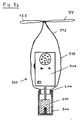
- the optical direction indicator is in the field of vision of the doctor during the puncture, as shown in FIG. 9 , this indicator 680 and 681 should be on the handle 600a of the ultrasound probe.
Landscapes
- Health & Medical Sciences (AREA)
- Life Sciences & Earth Sciences (AREA)
- Surgery (AREA)
- Physics & Mathematics (AREA)
- General Health & Medical Sciences (AREA)
- Molecular Biology (AREA)
- Pathology (AREA)
- Radiology & Medical Imaging (AREA)
- Nuclear Medicine, Radiotherapy & Molecular Imaging (AREA)
- Engineering & Computer Science (AREA)
- Biomedical Technology (AREA)
- Heart & Thoracic Surgery (AREA)
- Medical Informatics (AREA)
- Veterinary Medicine (AREA)
- Animal Behavior & Ethology (AREA)
- Biophysics (AREA)
- Public Health (AREA)
- Optics & Photonics (AREA)
- Acoustics & Sound (AREA)
- Ultra Sonic Daignosis Equipment (AREA)
- Medical Preparation Storing Or Oral Administration Devices (AREA)
- External Artificial Organs (AREA)
- Measuring Pulse, Heart Rate, Blood Pressure Or Blood Flow (AREA)
Claims (7)
- Combinaison d'un appareil Doppler à ultrasons (400a) non stérile destiné à localiser et à ponctionner des vaisseaux sanguins, lequel appareil Doppler à ultrasons (400a) comporte une sonde (600) non stérile avec une rainure (610) s'étendant dans la direction du champ d'ultrasons émis, une unité électronique (400) non stérile et un câble (500) non stérile reliant la sonde (600) à l'unité électronique (400), et d'un emballage (100a) stérile destiné à l'appareil Doppler à ultrasons (400a), l'emballage stérile (100a) comportant un élément d'emballage (100) tubulaire et souple avec une ouverture (128) refermable et située à son extrémité proximale, et un embout (300) rigide, l'emballage stérile (100a) comportant un tube de guidage (340) destiné à une aiguille de ponction (380) et pouvant être positionné dans la rainure (610) de la sonde (600), l'embout (300) étant traversé par le tube de guidage (340) et étant fixé ou pouvant être assemblé à l'extrémité distale de l 'élément d'emballage (100) de telle sorte qu'au moins la sonde (600) et une partie du câble (500), côté sonde, de l'appareil Doppler à ultrasons (400a) non stérile puissent être placées à travers l'ouverture (128) refermable de l'élément d'emballage (100) dans celui-ci et que la sonde (600) puisse être guidée dans l'embout (300) de manière à pouvoir positionner le tube de guidage (340) sur le fond de la rainure (610).
- Combinaison selon la revendication 1, caractérisée en ce que le tube de guidage (340) est plus long que la rainure (610) de la sonde (600), en ce que l'embout (300) est conçu de telle sorte qu'une partie du tube de guidage (340) dépasse la rainure (610) de la sonde (600), guidée dans l'embout (300), dans la direction d'un champ d'ultrasons émis par la sonde et en ce que cette partie, dépassant la rainure (610), du tube de guidage est entourée d'une avancée (700).
- Combinaison selon la revendication 2, caractérisée en ce que l'avancée (700) est agencée dans une partie d'avancée (320) de l'embout (300).
- Combinaison selon la revendication 2 ou 3, caractérisée en ce que l'avancée (700) est constituée par un gel, gardant sa forme et contenant de l'eau, dont la surface (710) côté sonde est légèrement convexe et est agencée dans l'embout (300) de telle sorte que, lors de l'introduction de la sonde (600) dans l'embout (300), elle est légèrement repoussée par la surface (630), côté peau, de la sonde.
- Combinaison selon l'une des revendications 2 à 4, caractérisée en ce que, entre la sonde (600) introduite dans l'embout (300) et l'avancée (700), est agencée une plaque (331) qui est traversée par le tube de guidage (340) et qui a, côté peau, une surface concave ou convexe (331b) pour former une lentille de focalisation.
- Combinaison selon l'une des revendications 1 à 5, caractérisée en ce que le tube de guidage (340) est aussi fixé par une traverse (335) à l'embout (300).
- Combinaison selon l'une des revendications 1 à 6, caractérisée en ce que l'élément d'emballage (100) comporte à son autre extrémité une autre ouverture autour de laquelle est fixé un cadre (200) sur lequel l'embout (300) peut être monté.
Applications Claiming Priority (5)
| Application Number | Priority Date | Filing Date | Title |
|---|---|---|---|
| CH12793 | 1993-01-18 | ||
| CH127/93 | 1993-01-18 | ||
| CH2084/93 | 1993-07-12 | ||
| CH208493 | 1993-07-12 | ||
| PCT/CH1994/000007 WO1994015532A2 (fr) | 1993-01-18 | 1994-01-14 | Procede permettant de localiser et de ponctionner des vaisseaux sanguins |
Publications (2)
| Publication Number | Publication Date |
|---|---|
| EP0631491A1 EP0631491A1 (fr) | 1995-01-04 |
| EP0631491B1 true EP0631491B1 (fr) | 1999-03-24 |
Family
ID=25683600
Family Applications (1)
| Application Number | Title | Priority Date | Filing Date |
|---|---|---|---|
| EP94903716A Expired - Lifetime EP0631491B1 (fr) | 1993-01-18 | 1994-01-14 | Dispostif permettant de localiser et de ponctionner des vaisseaux sanguins |
Country Status (8)
| Country | Link |
|---|---|
| US (1) | US5490522A (fr) |
| EP (1) | EP0631491B1 (fr) |
| JP (1) | JPH07506997A (fr) |
| AT (1) | ATE177923T1 (fr) |
| AU (1) | AU672668B2 (fr) |
| CA (1) | CA2132309A1 (fr) |
| DE (1) | DE59407988D1 (fr) |
| WO (1) | WO1994015532A2 (fr) |
Families Citing this family (58)
| Publication number | Priority date | Publication date | Assignee | Title |
|---|---|---|---|---|
| ATE197743T1 (de) | 1995-08-04 | 2000-12-15 | Belle Gate Invest B V | Datenaustauschlsysteme mit tragbaren datenverarbeitungseinheiten |
| ES2147122B1 (es) * | 1998-04-08 | 2001-04-01 | Briones Escubos Jorge | Perfeccionamientos en fundas para transductores de exploraciones ecograficas. |
| DE19850224A1 (de) | 1998-10-26 | 2000-05-31 | Humboldt Uni Zu Berlin Univers | Anordnung zur Punktion von Gefäßen, inneren Organen und raumfordernden Prozessen |
| US6547739B2 (en) * | 2001-01-08 | 2003-04-15 | Ge Medical Systems Global Technology Company Llc | Transesophageal probe with improved control panel |
| US6755789B2 (en) * | 2002-02-05 | 2004-06-29 | Inceptio Medical Technologies, Llc | Ultrasonic vascular imaging system and method of blood vessel cannulation |
| US7806828B2 (en) * | 2002-02-05 | 2010-10-05 | Inceptio Medical Technologies, Lc | Multiplanar ultrasonic vascular sensor assembly and apparatus for movably affixing a sensor assembly to a body |
| US7837627B1 (en) * | 2002-05-10 | 2010-11-23 | Rick L Pruter | Sheath apparatus for guiding needles for use with a medical ultrasound transceiver |
| US6887263B2 (en) * | 2002-10-18 | 2005-05-03 | Radiant Medical, Inc. | Valved connector assembly and sterility barriers for heat exchange catheters and other closed loop catheters |
| US7244234B2 (en) | 2003-11-11 | 2007-07-17 | Soma Development Llc | Ultrasound guided probe device and method of using same |
| JP2008502402A (ja) * | 2004-06-16 | 2008-01-31 | グレーター グラスゴー エヌエイチエス ボード | 超音波導波路 |
| JP2008522705A (ja) * | 2004-12-13 | 2008-07-03 | コーニンクレッカ フィリップス エレクトロニクス エヌ ヴィ | カニューレ挿入システム |
| US8784336B2 (en) | 2005-08-24 | 2014-07-22 | C. R. Bard, Inc. | Stylet apparatuses and methods of manufacture |
| US8388546B2 (en) | 2006-10-23 | 2013-03-05 | Bard Access Systems, Inc. | Method of locating the tip of a central venous catheter |
| US7794407B2 (en) | 2006-10-23 | 2010-09-14 | Bard Access Systems, Inc. | Method of locating the tip of a central venous catheter |
| WO2008109346A1 (fr) * | 2007-03-05 | 2008-09-12 | University Of Pittsburgh - Of The Commonwealth System Of Higher Education | Combinaison d'images tomographiques in situ avec une vision directe dans des environnements stériles |
| US8781555B2 (en) | 2007-11-26 | 2014-07-15 | C. R. Bard, Inc. | System for placement of a catheter including a signal-generating stylet |
| US9521961B2 (en) | 2007-11-26 | 2016-12-20 | C. R. Bard, Inc. | Systems and methods for guiding a medical instrument |
| US10524691B2 (en) | 2007-11-26 | 2020-01-07 | C. R. Bard, Inc. | Needle assembly including an aligned magnetic element |
| US10751509B2 (en) | 2007-11-26 | 2020-08-25 | C. R. Bard, Inc. | Iconic representations for guidance of an indwelling medical device |
| EP2992825B1 (fr) | 2007-11-26 | 2017-11-01 | C.R. Bard Inc. | Système intégré pour placement intravasculaire d'un cathéter |
| US8849382B2 (en) | 2007-11-26 | 2014-09-30 | C. R. Bard, Inc. | Apparatus and display methods relating to intravascular placement of a catheter |
| US10449330B2 (en) | 2007-11-26 | 2019-10-22 | C. R. Bard, Inc. | Magnetic element-equipped needle assemblies |
| US9649048B2 (en) | 2007-11-26 | 2017-05-16 | C. R. Bard, Inc. | Systems and methods for breaching a sterile field for intravascular placement of a catheter |
| EP2080478A1 (fr) * | 2008-01-16 | 2009-07-22 | Giesen Design Consultancy BV | Dispositif pour le guidage d'un instrument médical invasif |
| US8478382B2 (en) | 2008-02-11 | 2013-07-02 | C. R. Bard, Inc. | Systems and methods for positioning a catheter |
| US9901714B2 (en) | 2008-08-22 | 2018-02-27 | C. R. Bard, Inc. | Catheter assembly including ECG sensor and magnetic assemblies |
| US8437833B2 (en) | 2008-10-07 | 2013-05-07 | Bard Access Systems, Inc. | Percutaneous magnetic gastrostomy |
| US9532724B2 (en) | 2009-06-12 | 2017-01-03 | Bard Access Systems, Inc. | Apparatus and method for catheter navigation using endovascular energy mapping |
| RU2691318C2 (ru) | 2009-06-12 | 2019-06-11 | Бард Аксесс Системс, Инк. | Способ позиционирования конца катетера |
| EP2464407A4 (fr) | 2009-08-10 | 2014-04-02 | Bard Access Systems Inc | Dispositifs et procédés pour électrographie endovasculaire |
| CN102665541B (zh) | 2009-09-29 | 2016-01-13 | C·R·巴德股份有限公司 | 与用于导管的血管内放置的设备一起使用的探针 |
| JP5363261B2 (ja) * | 2009-09-30 | 2013-12-11 | 日本コヴィディエン株式会社 | 医療機器用カバー |
| WO2011044421A1 (fr) * | 2009-10-08 | 2011-04-14 | C. R. Bard, Inc. | Entretoises utilisées avec une sonde ultrasonore |
| US8761862B2 (en) * | 2009-10-09 | 2014-06-24 | Stephen F. Ridley | Ultrasound guided probe device and sterilizable shield for same |
| US8496592B2 (en) | 2009-10-09 | 2013-07-30 | Stephen F. Ridley | Clamp for a medical probe device |
| BR112012019354B1 (pt) | 2010-02-02 | 2021-09-08 | C.R.Bard, Inc | Método para localização de um dispositivo médico implantável |
| WO2011150376A1 (fr) | 2010-05-28 | 2011-12-01 | C.R. Bard, Inc. | Appareil convenant à une utilisation avec un système de guidage d'insertion d'aiguille |
| EP4122385A1 (fr) | 2010-05-28 | 2023-01-25 | C. R. Bard, Inc. | Système de guidage d'introduction pour aiguilles et composants médicaux |
| CN103228219B (zh) | 2010-08-09 | 2016-04-27 | C·R·巴德股份有限公司 | 用于超声探测器头的支撑和覆盖结构 |
| JP5845260B2 (ja) | 2010-08-20 | 2016-01-20 | シー・アール・バード・インコーポレーテッドC R Bard Incorporated | Ecg支援カテーテル先端配置の再確認 |
| US8425425B2 (en) | 2010-09-20 | 2013-04-23 | M. Dexter Hagy | Virtual image formation method for an ultrasound device |
| WO2012058461A1 (fr) | 2010-10-29 | 2012-05-03 | C.R.Bard, Inc. | Mise en place assistée par bio-impédance d'un dispositif médical |
| JP6008960B2 (ja) | 2011-07-06 | 2016-10-19 | シー・アール・バード・インコーポレーテッドC R Bard Incorporated | 挿入案内システムのためのニードル長決定および較正 |
| USD699359S1 (en) | 2011-08-09 | 2014-02-11 | C. R. Bard, Inc. | Ultrasound probe head |
| USD724745S1 (en) | 2011-08-09 | 2015-03-17 | C. R. Bard, Inc. | Cap for an ultrasound probe |
| US9211107B2 (en) | 2011-11-07 | 2015-12-15 | C. R. Bard, Inc. | Ruggedized ultrasound hydrogel insert |
| WO2013188833A2 (fr) | 2012-06-15 | 2013-12-19 | C.R. Bard, Inc. | Appareil et procédés permettant la détection d'un capuchon amovible sur une sonde à ultrasons |
| EP2961323B1 (fr) * | 2013-02-26 | 2022-11-09 | C. R. Bard, Inc. | Structures de couplage pour sonde ultrasonore |
| US10085716B2 (en) * | 2013-03-15 | 2018-10-02 | J. Jordan Romano | System and method for sterile sheathing of a medical probe |
| EP3073910B1 (fr) | 2014-02-06 | 2020-07-15 | C.R. Bard, Inc. | Systèmes pour le guidage et le placement d'un dispositif intravasculaire |
| US10973584B2 (en) | 2015-01-19 | 2021-04-13 | Bard Access Systems, Inc. | Device and method for vascular access |
| WO2016210325A1 (fr) | 2015-06-26 | 2016-12-29 | C.R. Bard, Inc. | Interface de raccord pour système de positionnement de cathéter basé sur ecg |
| US11000207B2 (en) | 2016-01-29 | 2021-05-11 | C. R. Bard, Inc. | Multiple coil system for tracking a medical device |
| US11890138B2 (en) | 2018-06-07 | 2024-02-06 | Remington Medical, Inc. | Handheld ultrasound device and replaceable tips therefor |
| CN112867443B (zh) | 2018-10-16 | 2024-04-26 | 巴德阿克塞斯系统股份有限公司 | 用于建立电连接的安全装备连接系统及其方法 |
| TWI720398B (zh) * | 2019-01-03 | 2021-03-01 | 國立陽明大學 | 用於肋膜訊號分析辨識、追蹤測距及顯示的合併方法及其內針超音波系統 |
| US12544101B2 (en) | 2019-01-30 | 2026-02-10 | Bard Access Systems, Inc. | Systems and methods for tracking medical devices |
| EP3962364A4 (fr) | 2019-05-01 | 2023-08-30 | Bard Access Systems, Inc. | Dispositifs de ponction, systèmes de ponction comprenant ces dispositifs de ponction, et procédés associés |
Family Cites Families (15)
| Publication number | Priority date | Publication date | Assignee | Title |
|---|---|---|---|---|
| US3556079A (en) * | 1967-05-16 | 1971-01-19 | Haruo Omizo | Method of puncturing a medical instrument under guidance of ultrasound |
| DE1927868C3 (de) * | 1969-05-31 | 1975-06-05 | Siemens Ag, 1000 Berlin Und 8000 Muenchen | Vorrichtung zum genauen und schnellen Orten von Blutgefäßen oder dergleichen und zum treffsicheren Einführen einer Injektionskanüle in diese Gefäße |
| US3721227A (en) * | 1971-08-24 | 1973-03-20 | Nulty D Mc | Transducer for pulse-echo ultrasonic exploration |
| US4408692A (en) * | 1982-04-12 | 1983-10-11 | The Kendall Company | Sterile cover for instrument |
| JPS5982839A (ja) * | 1982-09-24 | 1984-05-14 | アドバンスト・テクノロジ−・ラボラトリ−ズ・インコ−ポレイテツド | 内部手術超音波走査用無菌サヤ器具 |
| DE3789477T2 (de) * | 1986-09-18 | 1994-07-14 | Alan R Selfridge | Vorrichtung für Anwendung in der Kanalisation von Blutgefässen. |
| US4898178A (en) * | 1987-04-24 | 1990-02-06 | Wedel Victor J | Monolithic disposable needle guide for ultrasound transducers |
| CH676787A5 (en) * | 1989-08-30 | 1991-03-15 | Sulzer Ag | Puncture needle device for blood vessel - uses ultrasonic transceiver enclosing needle for accurate location of blood vessel |
| US5131394A (en) * | 1990-03-28 | 1992-07-21 | Gehlbach Steve M | Ultrasonic guided needle |
| US5131395A (en) * | 1990-03-28 | 1992-07-21 | Gehlbach Steve M | Ultrasonic apparatus for guiding needles into surface vessels |
| US5076279A (en) * | 1990-07-17 | 1991-12-31 | Acuson Corporation | Needle guide for assembly upon an ultrasound imaging transducer |
| DE9012429U1 (de) * | 1990-08-30 | 1990-10-31 | Johnson & Johnson Medical GmbH, 2000 Norderstedt | Steriler Ultraschall-Abdeckschlauch |
| US5235987A (en) * | 1991-02-22 | 1993-08-17 | Dymax Corporation | Needle guide |
| US5261409A (en) * | 1991-05-27 | 1993-11-16 | Sulzer Brothers Limited | Puncturing device for blood vessels |
| EP0540461A1 (fr) * | 1991-10-29 | 1993-05-05 | SULZER Medizinaltechnik AG | Dispositif stérile de ponction des vaisseaux sanguins équipé d'une sonde non-stérile et système pour la mise en place de l'ensemble |
-
1994
- 1994-01-14 WO PCT/CH1994/000007 patent/WO1994015532A2/fr not_active Ceased
- 1994-01-14 DE DE59407988T patent/DE59407988D1/de not_active Expired - Lifetime
- 1994-01-14 EP EP94903716A patent/EP0631491B1/fr not_active Expired - Lifetime
- 1994-01-14 AT AT94903716T patent/ATE177923T1/de not_active IP Right Cessation
- 1994-01-14 CA CA002132309A patent/CA2132309A1/fr not_active Abandoned
- 1994-01-14 JP JP6515566A patent/JPH07506997A/ja active Pending
- 1994-01-14 US US08/307,563 patent/US5490522A/en not_active Expired - Lifetime
- 1994-01-14 AU AU58071/94A patent/AU672668B2/en not_active Ceased
Also Published As
| Publication number | Publication date |
|---|---|
| US5490522A (en) | 1996-02-13 |
| WO1994015532A2 (fr) | 1994-07-21 |
| AU5807194A (en) | 1994-08-15 |
| AU672668B2 (en) | 1996-10-10 |
| EP0631491A1 (fr) | 1995-01-04 |
| ATE177923T1 (de) | 1999-04-15 |
| JPH07506997A (ja) | 1995-08-03 |
| CA2132309A1 (fr) | 1994-07-19 |
| DE59407988D1 (de) | 1999-04-29 |
| WO1994015532A3 (fr) | 1994-09-01 |
Similar Documents
| Publication | Publication Date | Title |
|---|---|---|
| EP0631491B1 (fr) | Dispostif permettant de localiser et de ponctionner des vaisseaux sanguins | |
| DE69124385T2 (de) | Ultraschall-bilderzeugungssystem mit zusätzlichem wandler | |
| DE69023367T2 (de) | Vorrichtung zur Steigerung von Ultraschall-Echos. | |
| DE69021158T2 (de) | Ultraschallkoppler und Herstellungsverfahren. | |
| DE69106643T2 (de) | Steriler Ultraschall-Abdeckschlauch. | |
| DE3342170C2 (fr) | ||
| DE3244667C2 (de) | Ultraschall-Applikator für die Biopsie | |
| EP0540461A1 (fr) | Dispositif stérile de ponction des vaisseaux sanguins équipé d'une sonde non-stérile et système pour la mise en place de l'ensemble | |
| CH688538A5 (de) | Ultraschallortungsgeraet mit Nadelfuehrung. | |
| EP0516582A1 (fr) | Dispositif de ponction des vaisseaux sanguins | |
| DE10148341A1 (de) | Verfahren zur Herstellung eines Modellsystems für Gefässmissbildungen | |
| DE4118610A1 (de) | Ankoppelvorrichtung zur einleitung akustischer wellen in den koerper eines lebewesens | |
| DE1541107A1 (de) | Trokar-Katheter | |
| DE1947123A1 (de) | Absaugvorrichtung fuer chirurgische Eingriffe in Koerperhoehlen | |
| DE3727190A1 (de) | Fuehrungsrohr fuer ein endoskop | |
| DE19527245A1 (de) | Vorrichtung für endoskopische oder gastroskopische Untersuchungen | |
| DE3324754A1 (de) | Ultraschallkontrastmittel sowie dessen herstellung | |
| DE3840077A1 (de) | Lithotriptor | |
| DE10029737B4 (de) | Navigation eines medizinischen Instrumentes | |
| DE7904837U1 (de) | Sonde für eine Ultraschallecho-Planigraphievorrichtung | |
| WO1999002100A1 (fr) | Systeme de guidage par coordonnees et de positionnement de reference | |
| EP0295521B1 (fr) | Transducteur ultrasonore déplaçable, notamment pour la diagnose de la hanche | |
| DE10254668A1 (de) | Gerät zur Behandlung von Gefäßdefekten | |
| DE2906474A1 (de) | Ultraschallwandler-sonde | |
| DE3714747C2 (fr) |
Legal Events
| Date | Code | Title | Description |
|---|---|---|---|
| PUAI | Public reference made under article 153(3) epc to a published international application that has entered the european phase |
Free format text: ORIGINAL CODE: 0009012 |
|
| 17P | Request for examination filed |
Effective date: 19940926 |
|
| AK | Designated contracting states |
Kind code of ref document: A1 Designated state(s): AT BE CH DE DK ES FR GB GR IE IT LI NL PT SE |
|
| 17Q | First examination report despatched |
Effective date: 19970505 |
|
| GRAG | Despatch of communication of intention to grant |
Free format text: ORIGINAL CODE: EPIDOS AGRA |
|
| GRAG | Despatch of communication of intention to grant |
Free format text: ORIGINAL CODE: EPIDOS AGRA |
|
| GRAH | Despatch of communication of intention to grant a patent |
Free format text: ORIGINAL CODE: EPIDOS IGRA |
|
| GRAH | Despatch of communication of intention to grant a patent |
Free format text: ORIGINAL CODE: EPIDOS IGRA |
|
| GRAA | (expected) grant |
Free format text: ORIGINAL CODE: 0009210 |
|
| AK | Designated contracting states |
Kind code of ref document: B1 Designated state(s): AT BE CH DE DK ES FR GB GR IE IT LI NL PT SE |
|
| PG25 | Lapsed in a contracting state [announced via postgrant information from national office to epo] |
Ref country code: SE Free format text: THE PATENT HAS BEEN ANNULLED BY A DECISION OF A NATIONAL AUTHORITY Effective date: 19990324 Ref country code: IT Free format text: LAPSE BECAUSE OF FAILURE TO SUBMIT A TRANSLATION OF THE DESCRIPTION OR TO PAY THE FEE WITHIN THE PRESCRIBED TIME-LIMIT;WARNING: LAPSES OF ITALIAN PATENTS WITH EFFECTIVE DATE BEFORE 2007 MAY HAVE OCCURRED AT ANY TIME BEFORE 2007. THE CORRECT EFFECTIVE DATE MAY BE DIFFERENT FROM THE ONE RECORDED. Effective date: 19990324 Ref country code: GR Free format text: LAPSE BECAUSE OF NON-PAYMENT OF DUE FEES Effective date: 19990324 Ref country code: ES Free format text: THE PATENT HAS BEEN ANNULLED BY A DECISION OF A NATIONAL AUTHORITY Effective date: 19990324 |
|
| REF | Corresponds to: |
Ref document number: 177923 Country of ref document: AT Date of ref document: 19990415 Kind code of ref document: T |
|
| REG | Reference to a national code |
Ref country code: CH Ref legal event code: EP |
|
| REG | Reference to a national code |
Ref country code: IE Ref legal event code: FG4D Free format text: GERMAN |
|
| REF | Corresponds to: |
Ref document number: 59407988 Country of ref document: DE Date of ref document: 19990429 |
|
| PG25 | Lapsed in a contracting state [announced via postgrant information from national office to epo] |
Ref country code: PT Free format text: LAPSE BECAUSE OF FAILURE TO SUBMIT A TRANSLATION OF THE DESCRIPTION OR TO PAY THE FEE WITHIN THE PRESCRIBED TIME-LIMIT Effective date: 19990624 Ref country code: DK Free format text: LAPSE BECAUSE OF FAILURE TO SUBMIT A TRANSLATION OF THE DESCRIPTION OR TO PAY THE FEE WITHIN THE PRESCRIBED TIME-LIMIT Effective date: 19990624 |
|
| ET | Fr: translation filed | ||
| GBT | Gb: translation of ep patent filed (gb section 77(6)(a)/1977) |
Effective date: 19990622 |
|
| PG25 | Lapsed in a contracting state [announced via postgrant information from national office to epo] |
Ref country code: IE Free format text: LAPSE BECAUSE OF NON-PAYMENT OF DUE FEES Effective date: 19991019 |
|
| REG | Reference to a national code |
Ref country code: IE Ref legal event code: FD4D |
|
| PG25 | Lapsed in a contracting state [announced via postgrant information from national office to epo] |
Ref country code: AT Free format text: LAPSE BECAUSE OF NON-PAYMENT OF DUE FEES Effective date: 20000114 |
|
| PLBE | No opposition filed within time limit |
Free format text: ORIGINAL CODE: 0009261 |
|
| STAA | Information on the status of an ep patent application or granted ep patent |
Free format text: STATUS: NO OPPOSITION FILED WITHIN TIME LIMIT |
|
| PG25 | Lapsed in a contracting state [announced via postgrant information from national office to epo] |
Ref country code: LI Free format text: LAPSE BECAUSE OF NON-PAYMENT OF DUE FEES Effective date: 20000131 Ref country code: CH Free format text: LAPSE BECAUSE OF NON-PAYMENT OF DUE FEES Effective date: 20000131 Ref country code: BE Free format text: LAPSE BECAUSE OF NON-PAYMENT OF DUE FEES Effective date: 20000131 |
|
| 26N | No opposition filed | ||
| BERE | Be: lapsed |
Owner name: DARDEL ERIC Effective date: 20000131 |
|
| REG | Reference to a national code |
Ref country code: CH Ref legal event code: PL |
|
| REG | Reference to a national code |
Ref country code: GB Ref legal event code: IF02 |
|
| PGFP | Annual fee paid to national office [announced via postgrant information from national office to epo] |
Ref country code: FR Payment date: 20100223 Year of fee payment: 17 |
|
| PGFP | Annual fee paid to national office [announced via postgrant information from national office to epo] |
Ref country code: GB Payment date: 20100121 Year of fee payment: 17 Ref country code: DE Payment date: 20100121 Year of fee payment: 17 |
|
| PGFP | Annual fee paid to national office [announced via postgrant information from national office to epo] |
Ref country code: NL Payment date: 20100118 Year of fee payment: 17 |
|
| REG | Reference to a national code |
Ref country code: NL Ref legal event code: V1 Effective date: 20110801 |
|
| GBPC | Gb: european patent ceased through non-payment of renewal fee |
Effective date: 20110114 |
|
| REG | Reference to a national code |
Ref country code: FR Ref legal event code: ST Effective date: 20110930 |
|
| PG25 | Lapsed in a contracting state [announced via postgrant information from national office to epo] |
Ref country code: FR Free format text: LAPSE BECAUSE OF NON-PAYMENT OF DUE FEES Effective date: 20110131 |
|
| PG25 | Lapsed in a contracting state [announced via postgrant information from national office to epo] |
Ref country code: GB Free format text: LAPSE BECAUSE OF NON-PAYMENT OF DUE FEES Effective date: 20110114 |
|
| PG25 | Lapsed in a contracting state [announced via postgrant information from national office to epo] |
Ref country code: NL Free format text: LAPSE BECAUSE OF NON-PAYMENT OF DUE FEES Effective date: 20110801 |
|
| REG | Reference to a national code |
Ref country code: DE Ref legal event code: R119 Ref document number: 59407988 Country of ref document: DE Effective date: 20110802 |
|
| PG25 | Lapsed in a contracting state [announced via postgrant information from national office to epo] |
Ref country code: DE Free format text: LAPSE BECAUSE OF NON-PAYMENT OF DUE FEES Effective date: 20110802 |