EP0631981A1 - Verfahren und Apparat zum Aktivieren von Kohlenstoff enthaltendem Stoff - Google Patents
Verfahren und Apparat zum Aktivieren von Kohlenstoff enthaltendem Stoff Download PDFInfo
- Publication number
- EP0631981A1 EP0631981A1 EP94109497A EP94109497A EP0631981A1 EP 0631981 A1 EP0631981 A1 EP 0631981A1 EP 94109497 A EP94109497 A EP 94109497A EP 94109497 A EP94109497 A EP 94109497A EP 0631981 A1 EP0631981 A1 EP 0631981A1
- Authority
- EP
- European Patent Office
- Prior art keywords
- reactor
- drum
- carbon
- containing material
- preheating
- Prior art date
- Legal status (The legal status is an assumption and is not a legal conclusion. Google has not performed a legal analysis and makes no representation as to the accuracy of the status listed.)
- Granted
Links
Images


Classifications
-
- C—CHEMISTRY; METALLURGY
- C01—INORGANIC CHEMISTRY
- C01B—NON-METALLIC ELEMENTS; COMPOUNDS THEREOF; METALLOIDS OR COMPOUNDS THEREOF NOT COVERED BY SUBCLASS C01C
- C01B32/00—Carbon; Compounds thereof
- C01B32/30—Active carbon
- C01B32/312—Preparation
- C01B32/336—Preparation characterised by gaseous activating agents
-
- C—CHEMISTRY; METALLURGY
- C01—INORGANIC CHEMISTRY
- C01B—NON-METALLIC ELEMENTS; COMPOUNDS THEREOF; METALLOIDS OR COMPOUNDS THEREOF NOT COVERED BY SUBCLASS C01C
- C01B32/00—Carbon; Compounds thereof
- C01B32/30—Active carbon
- C01B32/39—Apparatus for the preparation thereof
Definitions
- the present invention relates to a process and an apparatus for activating carbon-containing material.
- Activated charcoal is obtained by activating carbon-based material derived essentially from bituminous coals, peat, coconut shells, wood, sawdust, etc. by means of activation processes which are designated as chemical or physical.
- Chemical activation uses the particular action of some inorganic compounds (activating agents) during the carbonization step, which is performed at temperatures of 400 to 600 o C.
- the material is initially impregnated with appropriate chemicals which, when heated, release oxidizing gases that degrade the organic molecules.
- the main known activating agents are zinc chloride and phosphoric acid; positive results have been obtained by using sulfates or phosphates of alkaline metals, potassium thiocyanide, and manganese sulfide. Chemical activation is about to be abandoned since the step for the removal of the activating agent entails considerable ecological problems.
- Physical or thermal activation is performed with gaseous activating agents that selectively oxidise the carbon-containing material.
- the treatment which is usually preceded by carbonization of the raw material so as to reduce its content of volatile substances, uses air, water vapor or carbon dioxide. During the activation step, part of the carbon is burned, consequently increasing porosity.
- Oxidation with air is performed at low temperatures, but the exothermic nature of the reaction entails difficulty in managing it; it is used to produce charcoals having a low level of activity. Conversely, since treatment with CO2 or H2O is endothermic, it is easy to control and thus more widely used despite its high process temperatures.
- Multiple-hearth furnaces are those most widely used to activate charcoal and are constituted by a metal tower which is internally lined with refractory material and in which various tables are arranged.
- a shaft rotates at the vertical axis of the tower and has rotating arms fixed thereto; said arms have inclined vanes which have the purpose of moving the material.
- the charcoal which is loaded from above, encounters the steam, which is supplied from the lower part, and falls through holes onto the underlying tables since it is moved by the vanes.
- These reactors have the advantage of well-established technology and high reliability, but they have several problems, including poor efficiency in reaction, which is linked to the particular type of contact between the phases occurring in this reaction. Very poor contact leads to long permanence times, with consequent large volumes and low specific productivity. Furthermore, apparatuses using multiple-table furnaces are very large and complex and therefore require large investments and onerous maintenance operations.
- Rotary tubular reactors are instead essentially constituted by a rotating cylinder, at the ends whereof the charcoal and the steam are loaded in countercurrent. These apparatuses are simple but have the drawback that they do not provide good contact between the reagents, and this leads most of all to low productivity.
- Fluid-bed furnaces have been adapted to this production in recent years. These furnaces are internally lined with refractory material, and a porous plate is arranged in the lower portion of the furnace; the charcoal is fed onto said plate and the steam passes therethrough.
- the bed during agitation, practically doubles its height, providing excellent contact between the phases.
- This type of apparatus offers, among its many advantages, considerable temperature uniformity, highly effective gas-solid exchange and therefore low permanence times and considerable potential.
- the fluid bed has, among its disadvantages, the fact that it fragments the product, that it creates considerable erosion problems inside the reactor, and that it furthermore requires high investment costs.
- the aim of the present invention is to solve the problems described above with reference to known types of apparatus and process for the thermal activation of charcoal by providing a process and an apparatus for activating carbon-containing materials that is highly productive with low investment costs.
- an object of the invention is to provide an apparatus that ensures excellent steam-charcoal contact with consequent high reaction efficiencies.
- Another object of the present invention is to provide an apparatus that entails a reduced consumption of charcoal, with respect to conventional apparatuses, during the activation reaction.
- Another object of the invention is to provide an apparatus for activating carbon-containing materials that has considerably lower running costs than known apparatuses.
- Another object of the invention is to provide an apparatus which is structurally simple, dimensionally compact, and very simple in operation.
- Another object of the invention is to provide an apparatus that allows to act independently on the reaction parameters, i.e. temperatures, permanence time of the material in the reactor, and weight ratio between the reagents.
- an apparatus for activating carbon-containing material characterized in that it comprises: means for feeding the carbon-containing material to be activated into a drum-shaped reactor which is arranged so that its axis is substantially horizontal and has means for moving the material around and along its axis; heating means arranged outside said reactor; means for injecting a stream of superheated steam inside said reactor; and means for discharging the activated carbon-containing material outside said reactor.
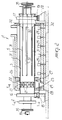
- the apparatus comprises means 2 for feeding the carbon-containing material to be activated into a drum-shaped reactor 3 which is arranged so that its axis is substantially horizontal and has means for moving the carbon-containing material around and along its axis 3a.
- the apparatus comprises heating means which are arranged outside the drum-shaped reactor 3, means for injecting a stream of superheated steam inside the reactor 3, and means for discharging the activated carbon-containing material outside the drum-shaped reactor 3.
- the apparatus according to the present invention also advantageously comprises means for preheating the carbon-containing material to be activated before introducing it in the reactor 3.
- the means for preheating the carbon-containing material to be activated are constituted by a preheating drum 4 which is arranged coaxially inside the drum-shaped reactor 3.
- the preheating drum 4 and the reactor 3 are rigidly coupled together in their rotation about the common axis 3a, are rotatably supported about said axis 3a, and are partially accommodated inside a heating muffle 5.
- Loading ports 6 are formed in the skirt of one of the end regions of the preheating drum 4 that protrude from the reactor 3 and are distributed around the axis 3a; the carbon-containing material to be processed passes through said ports and is introduced in the preheating drum 4.
- the means for introducing the carbon-containing material in the preheating drum 4 are preferably constituted by a wheel 7 which is fixed coaxially around the preheating drum 4 at the loading ports 6. Said wheel 7 is partially immersed, with its lower portion, inside a tank 8 for the carbon-containing material to be processed and, as shown in greater detail in figure 5, has a plurality of vanes 9 extending along substantially spiral-shaped paths that converge towards the preheating drum 4, so that by rotating the reactor 3 and the preheating drum 4 about the axis 3a, the vanes 9 pick up the carbon-containing material that is present in the tank 8 and lift it, conveying it by gravity to the loading ports 6 of the preheating drum 4.
- a screw feeder 10 is accommodated in the portion of the preheating drum 4 that lies between the loading ports 6 and the muffle 5; said screw feeder is arranged coaxially with respect to the preheating drum 4 and is driven by means of an appropriate variable-speed motor 10a arranged outside the preheating drum 4, so as to cause the advancement of the carbon-containing material introduced in the first portion of the preheating drum 4.
- Means for moving the carbon-containing material around and along the axis 3a are provided inside the preheating drum 4.
- Said movement means are appropriately constituted by a continuous or discontinuous cylindrical helix 11 which is fixed to the internal surface of the preheating drum 4.
- a burner 12 which is arranged at the axis 3a and is supplied through a duct that passes coaxially through the shaft of the screw feeder 10.
- Discharge ports 13 are formed proximate to the opposite end of the preheating drum 4, in any case still inside the muffle 5, and connect the preheating drum 4 to the inside of the reactor 3.
- Means for moving the carbon-containing material around and along the axis of the reactor are provided inside the reactor 3 as well.
- the reactor 3 is constituted by a chamber that has an annular cross-section and runs around the preheating drum 4, and the means for moving the carbon-containing material are constituted by vanes 14 which are arranged so as to form a continuous or discontinuous cylindrical helix and are fixed to the outer surface of the preheating drum 4.
- auxiliary vanes 15 which are fixed to said vanes 14.
- the drum-shaped reactor 3 has, at its axial ends, regions 16 and 17 having an increased diameter which rest on motorized rollers 18 and on idler rollers 19.
- the rollers 18 are rotated about their axis, for example by means of variable-displacement hydraulic motors, and rotate the drum-shaped reactor 3 by direct contact.
- the idler rollers 19 are appropriately mounted on a carriage 20 that can slide parallel to the axis 3a so as to compensate for the axial elongations of the drum-shaped reactor 3 caused by its heating.
- the drum-shaped reactor 3 has, proximate to its axial end which lies opposite to the end proximate to which the ports 13 for discharge into the preheating drum 4 are arranged, discharge ports 21 through which the activated carbon-containing material and the reaction gases are removed from the drum-shaped reactor 3. More particularly, the discharge ports 21 are formed inside the heating muffle 5 in a chamber 22 which is separated from the region of the muffle in which the means for heating the drum-shaped reactor 3 are located.
- the chamber 22 where the gas separates from the activated charcoal is provided, in a downward region, with a port 23, and a hopper 24 for collecting the material delivered by the reactor 3 is provided at said port 23.
- the means for heating the drum-shaped reactor 3 are constituted by a plurality of burners 25 which are arranged inside the heating muffle 5 in a region which, as mentioned, is separated by means of a partition 26 from the chamber 22 in which the processed material is discharged.
- the gases produced by the reaction of the activation of the carbon-containing material are also used to heat the reactor 3.
- the chamber 22 is in fact connected to the region of the muffle that accommodates the burners 25 through passages 27 which are shaped like an ejector body; a comburent gas, such as for example air or oxygen, is injected through said passages 27.
- a nozzle 28 coaxially to the passages 27 there is a nozzle 28 which is supplied with the comburent gas by an impeller 29.
- the aperture of the nozzle 28, and therefore the flow-rate of the comburent gas, as well as its pressure, are adjustable in a per se known manner, for example by means of a threaded rod 30 and an adjustment valve 29a, from the outside of the heating muffle 5.
- the passages 27 and the nozzles 28 form true ejectors that extract the gases produced by the activation reaction from the reactor 3 and feed them into the heating muffle 5, burning them.
- the means for injecting the stream of superheated steam inside the reactor 3 are constituted by a plurality of ducts 31 which are connected to the outer surface of the drum-shaped reactor 3 and end in the drum-shaped reactor 3 through holes 32 formed in the skirt of the reactor 3 proximate to the discharge ports 13 of the preheating drum 4 so that the carbon-containing material, during its advancement inside the reactor from the ports 13 toward the discharge port 21, is struck by the stream of steam flowing in the same direction.
- the ducts 31, which are appropriately shaped to compensate for thermal expansions, are connected to a rotating coupling 33 which is mounted on the end of the preheating drum 4 which is opposite to the end where the carbon-containing material is loaded.
- the rotating coupling 33 is connected to a steam generator 34 which can be heated by means of the fumes that leave the heating muffle 5, which have an enthalpic content that is sufficient to ensure the production of the amount of steam required for the activation process.
- the axial ends of the preheating drum 4 are appropriately pre-loaded with weights 35.
- the carbon-containing material to be processed is conveyed to the tank 8 by virtue of known means, such as for example a loading hopper 36 assisted by a screw feeder 37, whereas the activated carbon-containing material is removed from the port 23 and subjected to cooling cycles in a per se known manner.
- the carbon-containing material introduced in the preheating drum 4 advances along said preheating drum 4 up to the discharge ports 13, thus preheating. It should be noted that the preheating of the material inside the preheating drum 4 occurs directly.
- the preheated carbon-containing material passes into the drum-shaped reactor 3, where it makes contact with the superheated steam and gradually advances inside the reactor 3 in the opposite direction with respect to the direction followed inside the preheating drum 4.
- the vanes 14 and 15 control the advancement of the carbon-containing material during the activation reaction, and at the same time their shape stirs the material, forcing the steam to pass, during its motion, through the bed of carbon-containing material, thus striking it directly. In this manner the steam is prevented from flowing only over the surface of the bed of material arranged on the bottom of the reactor, facilitating contact between the reacting phases.
- the vanes 15, by virtue of the rotation of the reactor 3, lift the carbon-containing material and then let it fall, helping to constantly renew the surface of the layer of carbon-containing material that is in contact with the steam and thus further improving the effectiveness of the gas-solid exchange.
- a temperature substantially comprised between 675 o C and 1100 o C is maintained inside the reactor 3, and the activation reaction occurs substantially at atmospheric pressure.
- the reaction products At the end of the path inside the reactor 3, the reaction products, together with the excess steam, leave the reactor 3 through the ports 21. Since the reaction gases are constituted by combustible products, H2 and CO, they are introduced in the combustion chamber of the muffle 5 through the passages-ejectors 27 and are burned, providing the heat required to sustain the endothermic activation reaction. In practice, the operating conditions of reheating occur inside the muffle 5. In practice, the burners 25 act as pilot burners and are activated only during startup and to adjust the reaction temperature, which is maintained, as mentioned, preferably between 675 o C and 1100 o C.
- the burned gases generated in the combustion chamber of the muffle 5 leave the muffle 5 with a still high enthalpic content that is used in the boiler 34 to generate the steam required for the process.
- the steam that leaves the boiler 34 is saturated and enters the reactor 3 after flowing inside the ducts 31, along which the steam is superheated.
- the materials employed, as well as the dimensions, may be any according to the requirements and the state of the art.
Landscapes
- Chemical & Material Sciences (AREA)
- Organic Chemistry (AREA)
- Inorganic Chemistry (AREA)
- Carbon And Carbon Compounds (AREA)
- Electric Double-Layer Capacitors Or The Like (AREA)
Applications Claiming Priority (2)
| Application Number | Priority Date | Filing Date | Title |
|---|---|---|---|
| IT93MI001346A IT1264875B1 (it) | 1993-06-22 | 1993-06-22 | Procedimento di impianto per l'attivazione di materiale carbonioso |
| ITMI931346 | 1993-06-22 |
Publications (2)
| Publication Number | Publication Date |
|---|---|
| EP0631981A1 true EP0631981A1 (de) | 1995-01-04 |
| EP0631981B1 EP0631981B1 (de) | 1999-08-25 |
Family
ID=11366453
Family Applications (1)
| Application Number | Title | Priority Date | Filing Date |
|---|---|---|---|
| EP94109497A Expired - Lifetime EP0631981B1 (de) | 1993-06-22 | 1994-06-20 | Verfahren und Apparat zum Aktivieren von Kohlenstoff enthaltendem Stoff |
Country Status (6)
| Country | Link |
|---|---|
| US (1) | US5437845A (de) |
| EP (1) | EP0631981B1 (de) |
| AT (1) | ATE183723T1 (de) |
| CA (1) | CA2126378A1 (de) |
| DE (1) | DE69420203D1 (de) |
| IT (1) | IT1264875B1 (de) |
Cited By (4)
| Publication number | Priority date | Publication date | Assignee | Title |
|---|---|---|---|---|
| RU2118291C1 (ru) * | 1998-02-26 | 1998-08-27 | Общество с ограниченной ответственностью "ПлУГ" | Способ непрерывной переработки углеродсодержащего сырья и устройство для его осуществления |
| US6316378B1 (en) | 1999-03-17 | 2001-11-13 | Carbotex, Gmbh | Process for the production of shaped activated carbon |
| RU2208580C1 (ru) * | 2002-03-11 | 2003-07-20 | ЗАО "Дормашинвест" | Способ непрерывной переработки углеродосодержащего сырья и устройство для его осуществления |
| US8999885B2 (en) | 2013-01-09 | 2015-04-07 | General Electric Company | Methods of activating charcoal resulting from biomass gasification |
Families Citing this family (10)
| Publication number | Priority date | Publication date | Assignee | Title |
|---|---|---|---|---|
| US6946077B2 (en) * | 2000-11-30 | 2005-09-20 | Envirotrol, Inc. | pH stable activated carbon |
| US8597524B2 (en) * | 2004-09-13 | 2013-12-03 | Donnelly Labs Llc | Enclosed rotor-based cavitational and catalytic flow-through reaction chamber |
| US8691166B2 (en) * | 2008-01-08 | 2014-04-08 | Carbonxt Group Limited | System and method for activating carbonaceous material |
| US8628707B2 (en) * | 2008-01-08 | 2014-01-14 | Carbonxt Group Limited | System and method for making carbon foam anodes |
| US20090172998A1 (en) * | 2008-01-08 | 2009-07-09 | Carbonxt Group Limited | System and method for refining carbonaceous material |
| US8617492B2 (en) * | 2008-01-08 | 2013-12-31 | Carbonxt Group Limited | System and method for making low volatile carboneaceous matter with supercritical CO2 |
| US9272263B2 (en) * | 2012-09-24 | 2016-03-01 | Kappes, Cassiday & Associates | Sand bed downdraft furnace and activated carbon scrubber |
| CN105366673A (zh) * | 2014-08-21 | 2016-03-02 | 苏州格瑞展泰再生能源有限公司 | 一种精确控制卧式物理活化反应器及工艺 |
| CN106044767B (zh) * | 2016-08-16 | 2018-07-27 | 厦门中科城环新能源有限公司 | 一种炭化活化一体化加工装置及其加工方法 |
| US12269746B2 (en) * | 2020-07-21 | 2025-04-08 | Aura7 Usa Inc | Activated carbon balls and method for producing thereof |
Citations (4)
| Publication number | Priority date | Publication date | Assignee | Title |
|---|---|---|---|---|
| JPS4850990A (de) * | 1971-11-01 | 1973-07-18 | ||
| EP0076913A2 (de) * | 1981-10-08 | 1983-04-20 | Degussa Aktiengesellschaft | Verfahren und Vorrichtung zur Aktivierung von kohlenstoffhaltigem Material |
| EP0077462A1 (de) * | 1981-10-08 | 1983-04-27 | Degussa Aktiengesellschaft | Verfahren und Vorrichtung zum Aktivieren von Aktivkohle |
| EP0203006A1 (de) * | 1985-05-20 | 1986-11-26 | Compagnie Generale Des Matieres Nucleaires (Cogema) | Vorrichtung und Verfahren zur Regenerierung von Aktivkohle |
Family Cites Families (11)
| Publication number | Priority date | Publication date | Assignee | Title |
|---|---|---|---|---|
| DE245708C (de) * | ||||
| US612181A (en) * | 1898-10-11 | Harry spurrier | ||
| US813022A (en) * | 1905-01-16 | 1906-02-20 | Augustin L J Queneau | Charging-machine. |
| US1769412A (en) * | 1928-06-09 | 1930-07-01 | Traylor Engineering & Mfg Co | Rotary tube cooler |
| US2020506A (en) * | 1930-07-26 | 1935-11-12 | American Cyanamid & Chem Corp | Production of monocarboxylic acids and their derivatives |
| US2255539A (en) * | 1939-01-05 | 1941-09-09 | Ella Van Gorder | Apparatus for treatment of iron sulphate |
| US2560316A (en) * | 1946-02-20 | 1951-07-10 | Traylor Engineering & Mfg Comp | Apparatus for slaking lime |
| US2600871A (en) * | 1949-06-27 | 1952-06-17 | Gulf Research Development Co | Continuous conveyer-reactor chamber |
| US2787599A (en) * | 1952-05-03 | 1957-04-02 | Universal Oil Prod Co | Process for treating catalyst particles |
| US3871829A (en) * | 1972-10-20 | 1975-03-18 | Gen Electric | Calciner with baffle means |
| US4125437A (en) * | 1976-11-01 | 1978-11-14 | Bacon Conrad G | Distillation system |
-
1993
- 1993-06-22 IT IT93MI001346A patent/IT1264875B1/it active IP Right Grant
-
1994
- 1994-06-20 US US08/262,706 patent/US5437845A/en not_active Expired - Fee Related
- 1994-06-20 EP EP94109497A patent/EP0631981B1/de not_active Expired - Lifetime
- 1994-06-20 DE DE69420203T patent/DE69420203D1/de not_active Expired - Lifetime
- 1994-06-20 AT AT94109497T patent/ATE183723T1/de not_active IP Right Cessation
- 1994-06-21 CA CA002126378A patent/CA2126378A1/en not_active Abandoned
Patent Citations (4)
| Publication number | Priority date | Publication date | Assignee | Title |
|---|---|---|---|---|
| JPS4850990A (de) * | 1971-11-01 | 1973-07-18 | ||
| EP0076913A2 (de) * | 1981-10-08 | 1983-04-20 | Degussa Aktiengesellschaft | Verfahren und Vorrichtung zur Aktivierung von kohlenstoffhaltigem Material |
| EP0077462A1 (de) * | 1981-10-08 | 1983-04-27 | Degussa Aktiengesellschaft | Verfahren und Vorrichtung zum Aktivieren von Aktivkohle |
| EP0203006A1 (de) * | 1985-05-20 | 1986-11-26 | Compagnie Generale Des Matieres Nucleaires (Cogema) | Vorrichtung und Verfahren zur Regenerierung von Aktivkohle |
Non-Patent Citations (1)
| Title |
|---|
| DATABASE WPI Week 7347, Derwent World Patents Index; AN 73-71142U * |
Cited By (5)
| Publication number | Priority date | Publication date | Assignee | Title |
|---|---|---|---|---|
| RU2118291C1 (ru) * | 1998-02-26 | 1998-08-27 | Общество с ограниченной ответственностью "ПлУГ" | Способ непрерывной переработки углеродсодержащего сырья и устройство для его осуществления |
| US6316378B1 (en) | 1999-03-17 | 2001-11-13 | Carbotex, Gmbh | Process for the production of shaped activated carbon |
| DE19912154C5 (de) * | 1999-03-17 | 2007-02-01 | Carbotex Produktions-Und Veredelungsbetriebe Gmbh | Verfahren zur Herstellung von geformter Aktivkohle |
| RU2208580C1 (ru) * | 2002-03-11 | 2003-07-20 | ЗАО "Дормашинвест" | Способ непрерывной переработки углеродосодержащего сырья и устройство для его осуществления |
| US8999885B2 (en) | 2013-01-09 | 2015-04-07 | General Electric Company | Methods of activating charcoal resulting from biomass gasification |
Also Published As
| Publication number | Publication date |
|---|---|
| ITMI931346A0 (it) | 1993-06-22 |
| EP0631981B1 (de) | 1999-08-25 |
| IT1264875B1 (it) | 1996-10-17 |
| ATE183723T1 (de) | 1999-09-15 |
| DE69420203D1 (de) | 1999-09-30 |
| US5437845A (en) | 1995-08-01 |
| CA2126378A1 (en) | 1994-12-23 |
| ITMI931346A1 (it) | 1994-12-22 |
Similar Documents
| Publication | Publication Date | Title |
|---|---|---|
| EP0631981B1 (de) | Verfahren und Apparat zum Aktivieren von Kohlenstoff enthaltendem Stoff | |
| EP0224999B1 (de) | Pyrolyse- und Verbrennungsverfahren und -anlage | |
| US3647716A (en) | Transport reactor with a venturi tube connection to a combustion chamber for producing activated carbon | |
| CN106044767B (zh) | 一种炭化活化一体化加工装置及其加工方法 | |
| KR100707842B1 (ko) | 유기 물질 또는 유기 물질 혼합물들의 열분해 및 기체화를위한 방법 및 장치 | |
| US4046085A (en) | Method and apparatus for treating waste material in a counter-current incinerator | |
| CN108178353A (zh) | 一种颗粒活性炭吸附及再生集成处理方法 | |
| CN110127699B (zh) | 一种活性炭活化再生装置及活性炭再生方法和活化方法 | |
| KR20060100022A (ko) | 가연성 폐기물 무공해 탄화처리로 에너지생산 방법과 그시스템과 그리고 크랙킹 촉매와 그 제조방법 | |
| CN111892028A (zh) | 一种泥磷蒸馏回收单质磷方法 | |
| RU2118291C1 (ru) | Способ непрерывной переработки углеродсодержащего сырья и устройство для его осуществления | |
| JP2515870B2 (ja) | 可燃性汚染物質と廃棄物をクリ―ンエネルギ―と利用できる生成物として変換するプロセスと装置 | |
| CA1124183A (en) | Coal filtering for purifying waste water under continuous regeneration of coal and recovery of heat | |
| KR20070089037A (ko) | 대나무 활성탄 제조방법 및 제조장치 | |
| JP2001213616A (ja) | 活性炭の製造方法 | |
| US2086733A (en) | Production of sulphur dioxide | |
| CN1229055A (zh) | 利用炭黑制备活性炭的方法 | |
| US2057099A (en) | Production of sulphur dioxide | |
| JP3721531B2 (ja) | 活性炭の製造方法及び装置 | |
| JPS6144808B2 (de) | ||
| CN101072852A (zh) | 含碳材料气化方法与其实施设备 | |
| CN101306814A (zh) | 一种污水净化处理材料的制备方法和装置 | |
| JP3405702B2 (ja) | 活性炭製造装置 | |
| RU2095708C1 (ru) | Печь для термической обработки углеродсодержащих материалов | |
| ZA200102128B (en) | Method for producing directly reduced metal in a multi-tiered furnace. |
Legal Events
| Date | Code | Title | Description |
|---|---|---|---|
| PUAI | Public reference made under article 153(3) epc to a published international application that has entered the european phase |
Free format text: ORIGINAL CODE: 0009012 |
|
| AK | Designated contracting states |
Kind code of ref document: A1 Designated state(s): AT BE CH DE DK ES FR GB GR IE LI NL PT SE |
|
| 17P | Request for examination filed |
Effective date: 19950422 |
|
| 17Q | First examination report despatched |
Effective date: 19970806 |
|
| GRAG | Despatch of communication of intention to grant |
Free format text: ORIGINAL CODE: EPIDOS AGRA |
|
| GRAG | Despatch of communication of intention to grant |
Free format text: ORIGINAL CODE: EPIDOS AGRA |
|
| GRAH | Despatch of communication of intention to grant a patent |
Free format text: ORIGINAL CODE: EPIDOS IGRA |
|
| GRAH | Despatch of communication of intention to grant a patent |
Free format text: ORIGINAL CODE: EPIDOS IGRA |
|
| GRAA | (expected) grant |
Free format text: ORIGINAL CODE: 0009210 |
|
| AK | Designated contracting states |
Kind code of ref document: B1 Designated state(s): AT BE CH DE DK ES FR GB GR IE LI NL PT SE |
|
| PG25 | Lapsed in a contracting state [announced via postgrant information from national office to epo] |
Ref country code: SE Free format text: THE PATENT HAS BEEN ANNULLED BY A DECISION OF A NATIONAL AUTHORITY Effective date: 19990825 Ref country code: NL Free format text: LAPSE BECAUSE OF FAILURE TO SUBMIT A TRANSLATION OF THE DESCRIPTION OR TO PAY THE FEE WITHIN THE PRESCRIBED TIME-LIMIT Effective date: 19990825 Ref country code: LI Free format text: LAPSE BECAUSE OF FAILURE TO SUBMIT A TRANSLATION OF THE DESCRIPTION OR TO PAY THE FEE WITHIN THE PRESCRIBED TIME-LIMIT Effective date: 19990825 Ref country code: GR Free format text: LAPSE BECAUSE OF NON-PAYMENT OF DUE FEES Effective date: 19990825 Ref country code: FR Free format text: LAPSE BECAUSE OF FAILURE TO SUBMIT A TRANSLATION OF THE DESCRIPTION OR TO PAY THE FEE WITHIN THE PRESCRIBED TIME-LIMIT Effective date: 19990825 Ref country code: ES Free format text: THE PATENT HAS BEEN ANNULLED BY A DECISION OF A NATIONAL AUTHORITY Effective date: 19990825 Ref country code: CH Free format text: LAPSE BECAUSE OF FAILURE TO SUBMIT A TRANSLATION OF THE DESCRIPTION OR TO PAY THE FEE WITHIN THE PRESCRIBED TIME-LIMIT Effective date: 19990825 Ref country code: BE Free format text: LAPSE BECAUSE OF FAILURE TO SUBMIT A TRANSLATION OF THE DESCRIPTION OR TO PAY THE FEE WITHIN THE PRESCRIBED TIME-LIMIT Effective date: 19990825 Ref country code: AT Free format text: LAPSE BECAUSE OF FAILURE TO SUBMIT A TRANSLATION OF THE DESCRIPTION OR TO PAY THE FEE WITHIN THE PRESCRIBED TIME-LIMIT Effective date: 19990825 |
|
| REF | Corresponds to: |
Ref document number: 183723 Country of ref document: AT Date of ref document: 19990915 Kind code of ref document: T |
|
| REG | Reference to a national code |
Ref country code: CH Ref legal event code: EP |
|
| REF | Corresponds to: |
Ref document number: 69420203 Country of ref document: DE Date of ref document: 19990930 |
|
| REG | Reference to a national code |
Ref country code: IE Ref legal event code: FG4D |
|
| PG25 | Lapsed in a contracting state [announced via postgrant information from national office to epo] |
Ref country code: PT Free format text: LAPSE BECAUSE OF FAILURE TO SUBMIT A TRANSLATION OF THE DESCRIPTION OR TO PAY THE FEE WITHIN THE PRESCRIBED TIME-LIMIT Effective date: 19991125 Ref country code: DK Free format text: LAPSE BECAUSE OF FAILURE TO SUBMIT A TRANSLATION OF THE DESCRIPTION OR TO PAY THE FEE WITHIN THE PRESCRIBED TIME-LIMIT Effective date: 19991125 |
|
| PG25 | Lapsed in a contracting state [announced via postgrant information from national office to epo] |
Ref country code: DE Free format text: LAPSE BECAUSE OF FAILURE TO SUBMIT A TRANSLATION OF THE DESCRIPTION OR TO PAY THE FEE WITHIN THE PRESCRIBED TIME-LIMIT Effective date: 19991126 |
|
| EN | Fr: translation not filed | ||
| NLV1 | Nl: lapsed or annulled due to failure to fulfill the requirements of art. 29p and 29m of the patents act | ||
| REG | Reference to a national code |
Ref country code: CH Ref legal event code: PL |
|
| PG25 | Lapsed in a contracting state [announced via postgrant information from national office to epo] |
Ref country code: IE Free format text: LAPSE BECAUSE OF NON-PAYMENT OF DUE FEES Effective date: 20000620 Ref country code: GB Free format text: LAPSE BECAUSE OF NON-PAYMENT OF DUE FEES Effective date: 20000620 |
|
| PLBE | No opposition filed within time limit |
Free format text: ORIGINAL CODE: 0009261 |
|
| STAA | Information on the status of an ep patent application or granted ep patent |
Free format text: STATUS: NO OPPOSITION FILED WITHIN TIME LIMIT |
|
| 26N | No opposition filed | ||
| GBPC | Gb: european patent ceased through non-payment of renewal fee |
Effective date: 20000620 |
|
| REG | Reference to a national code |
Ref country code: IE Ref legal event code: MM4A |