EP0631990B1 - Procédé et appareil pour le préchauffage de la matière première pour un four de fusion de verre - Google Patents
Procédé et appareil pour le préchauffage de la matière première pour un four de fusion de verre Download PDFInfo
- Publication number
- EP0631990B1 EP0631990B1 EP94108601A EP94108601A EP0631990B1 EP 0631990 B1 EP0631990 B1 EP 0631990B1 EP 94108601 A EP94108601 A EP 94108601A EP 94108601 A EP94108601 A EP 94108601A EP 0631990 B1 EP0631990 B1 EP 0631990B1
- Authority
- EP
- European Patent Office
- Prior art keywords
- melting furnace
- glass melting
- gases
- heat exchanger
- glass
- Prior art date
- Legal status (The legal status is an assumption and is not a legal conclusion. Google has not performed a legal analysis and makes no representation as to the accuracy of the status listed.)
- Expired - Lifetime
Links
Images
Classifications
-
- C—CHEMISTRY; METALLURGY
- C03—GLASS; MINERAL OR SLAG WOOL
- C03B—MANUFACTURE, SHAPING, OR SUPPLEMENTARY PROCESSES
- C03B3/00—Charging the melting furnaces
- C03B3/02—Charging the melting furnaces combined with preheating, premelting or pretreating the glass-making ingredients, pellets or cullet
- C03B3/023—Preheating
-
- Y—GENERAL TAGGING OF NEW TECHNOLOGICAL DEVELOPMENTS; GENERAL TAGGING OF CROSS-SECTIONAL TECHNOLOGIES SPANNING OVER SEVERAL SECTIONS OF THE IPC; TECHNICAL SUBJECTS COVERED BY FORMER USPC CROSS-REFERENCE ART COLLECTIONS [XRACs] AND DIGESTS
- Y02—TECHNOLOGIES OR APPLICATIONS FOR MITIGATION OR ADAPTATION AGAINST CLIMATE CHANGE
- Y02P—CLIMATE CHANGE MITIGATION TECHNOLOGIES IN THE PRODUCTION OR PROCESSING OF GOODS
- Y02P40/00—Technologies relating to the processing of minerals
- Y02P40/50—Glass production, e.g. reusing waste heat during processing or shaping
Definitions
- the invention relates to a method for preheating glass and feed containing organic admixtures in one indirect heat exchanger that has at least one preheating shaft and has a heating chamber adjacent to it Temperatures up to just below the maximum Softening temperature of the glass for subsequent insertion in a glass melting furnace under guidance of the feed material in the at least one preheating shaft and by applying the Heating chamber with exhaust gases from the glass melting furnace.
- organic admixtures include paper and plastics and adhesive of labels, plastic coatings of bottles, plastic capsules for bottles, but also Contamination caused by remnants of the original content be formed. After all, they are organic Accompanying substances also cork.
- preheating temperatures for the load are turned off chosen for economic reasons as high as possible, namely after Possibility to just below the temperature at which the Load tends to form lumps. This process occurs Presence of broken glass above the softening temperature of the glass, which is why preheating in general Temperatures of a maximum of about 550 ° C ended.
- the US-PS 5 156 545 is another foreign Known method, which is primarily intended for glass fibers are contaminated with organic substances Process pyrolysis in such a way that it for the Remelting can be used in a glass melting furnace can. However, this is not one Preheating process because it is allowed that the end product of the Processing for stockpile is promoted.
- the pyrolysis process is in a relatively loose fill carried out by means of a Belt conveyor is passed through a combustion chamber. Also the feed material must tend to stick be counteracted by limiting the temperature, so that the temperature must be kept below 550 ° C. Regarding the gas required for the pyrolysis is only indicated that this should contain less than 10% oxygen, to avoid local temperature peaks that lead to a Can cause the load to stick.
- the invention is therefore based on the object of a method of to further develop the genus described at the beginning, that also feed with organic admixtures of type mentioned at relatively high temperatures can be preheated without the decay products of the organic admixtures, the so-called carbonization gases, to the Can get atmosphere and without expensive Gas circulation devices and / or afterburning in special combustion units would have to be carried out. In particular, however, a high proportion of those in the exhaust gases of the glass melting furnace contained by the Preheating process can be recovered.
- the task is solved at the beginning specified method according to the invention in that the from organic admixtures formed gases and vapors at least partially, but preferably completely, from the heat exchanger outside the glass melt in the glass melting furnace are introduced.
- the glass melting furnace itself serves as Combustion unit for the organic admixtures formed gases and vapors. Because in such a glass melting furnace Usually temperatures between 1100 and 1600 ° C are present and sometimes very hot flames when using burners are formed, said gases and vapors become too largely harmless compounds burned together discharged to the atmosphere with the flue gas from the glass melting furnace can be. It is understood that these exhaust gases, if necessary passed through special filter and gas washing systems can be the combustion products from the organic However, admixtures provide for these exhaust gas cleaning devices no special additional burden.
- the load in the Heat exchanger in the at least one vertically arranged Preheating shaft is guided from top to bottom and when the Gases and vapors from the bottom of this at least one Preheating shaft are suctioned off.
- the feed material has the highest preheating shaft Temperature, especially when the exhaust gas from the glass melting furnace is passed in countercurrent through the heating chamber, i.e. from the bottom up.
- the gases and vapors released from the load can be fed to the glass melting furnace at various points are, for example in the supplied combustion air, in the Combustion chamber of the glass melting furnace and / or into a burner, for example, if it has coaxial burner tubes is executed.
- the invention also relates to a device for Carrying out the method specified at the beginning with a indirect heat exchanger that has at least one preheating shaft for the feed material and one to the Preheating shaft adjacent and separated from it Has heating chamber for the passage of a heating medium, wherein a glass melting furnace is connected downstream of the heat exchanger, the exhaust pipe of the heating chamber of the heat exchanger is switched on and its insertion opening with the at least a preheating shaft is connected by a conveyor.
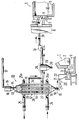
- the figure shows two partial sections through one and the same glass melting furnace 1, namely an axial section through the bottom left the insertion area 2 of the furnace, to which one is not closer designated insertion opening, which is located in a so-called "dog house” 3 is arranged, and in the right half a cross section in Area of a burner 4, of which only the nozzle block 5 with its burner opening 6 is shown. Above the burner opening 6 there is an air supply opening 7 through which the combustion air flows in the direction of the arrow. The combustion air is also through an air preheater 8 preheated, of which only one Partial section is shown.
- An upstream of the glass melting furnace 1 is an indirect one Heat exchanger 10 to which three vertical preheating shafts 11 and include a heating chamber 12, whose volumes through the walls of the Preheating shafts 11 are separated from each other.
- the Preheating shafts 11 start from a distribution device 13 which via a metering and charging lock 14 with a storage container 15 is connected, in which the load 16 is located.
- the storage container is by a belt conveyor 17 with the Loading goods supplied, which in the present case from one Mixture of cullet and batch exists.
- the preheating shafts 11 united by a collecting device 18, which has the shape of a Has funnel, and the discharge opening 19 to one Conveyor 20 leads to which a vibrating conveyor trough 21 heard.
- a collecting device 18 which has the shape of a Has funnel
- the discharge opening 19 to one Conveyor 20 leads to which a vibrating conveyor trough 21 heard.
- This opens into an intermediate container 22, which with an insertion device 23 is connected, through which the preheated load in strips on the glass melt in the melting tank 9 is inserted.
- the heating chamber 12 is at its lower end with an exhaust pipe 24 connected to which a ring line 24a belongs, which does not have branch lines shown is connected to the heating chamber 12.
- the Exhaust line 24 comes from glass melting furnace 1.
- the upper end of the heating chamber 12 is an analog one Ring line 25a connected to a further exhaust line 25, which to leads to a fireplace, not shown here. That way it will Exhaust gas in the heating chamber 12 in countercurrent to the Feed material guided in the preheating shafts Direction of movement is indicated by arrow 26.
- the preheating shafts 11 have in their lower area Discharge openings 27, which are in a common carbonization line 28 flow out.
- this carbonization line 28 is for Separation of any solid particles using a cyclone separator 29 with a closable discharge opening 30.
- a suction fan 31 is arranged through the carbonization line 28 that the smoldering gases with the formation of a slight negative pressure in the Preheating shafts can be extracted from these. From the suction fan 31 leads to a further section of the carbonization line 28 Air supply opening 7 in which there is an inlet opening 32 for the Smoldering gas is located. From here, the carbonization gas is through the Combustion air led into the interior of the glass melting furnace 1. And completely burned there.
- Discharge openings 33 for the water vapor. These vents are at a point of such temperature at which none Decomposition of the organic admixtures is caused.
- the Discharge openings 33 open into a common suction line 34, with the carbonization line 28 in the manner shown can be connected. However, it is also possible to use the suction line 34 connect directly to the fireplace, not shown.
- the Heating chamber 12 surrounds the preheating 11 so that a intensive heat transfer through the walls of the preheating shafts 11 is guaranteed. As already said, the heat exchange takes place in countercurrent instead, so that the highest temperature in Load material 16 in the lower area of the preheating shafts 11 occurs.
Landscapes
- Chemical & Material Sciences (AREA)
- Engineering & Computer Science (AREA)
- Materials Engineering (AREA)
- Organic Chemistry (AREA)
- Waste-Gas Treatment And Other Accessory Devices For Furnaces (AREA)
- Glass Melting And Manufacturing (AREA)
- Processing Of Solid Wastes (AREA)
Claims (15)
- Procédé de préchauffage de verre et d'une charge de matières premières (16) contenant des constituants organiques, dans un échangeur de chaleur indirect (10), qui présente au moins un puits de préchauffage (11) et une chambre de chauffage (12) qui le jouxte, pour les porter à des températures jusqu'au maximum juste en-dessous de la température de ramollissement du verre pour les introduire ensuite dans un four de fusion du verre (1), sous condition du passage de la charge de matières premières (16) dans le puits de préchauffage (11) dont il y a au moins un et de l'exposition de la chambre de chauffe (12) à des gaz d'évacuation provenant du four de fusion (1), caractérisé par le fait que les gaz et les vapeurs formés à partir des constituants organiques sont, au moins partiellement, introduits, depuis l'échangeur de chaleur (10), dans le four de fusion du verre (1), en dehors du bain de fusion du verre.
- Procédé selon la revendication 1, caractérisé par le fait que le dégagement des gaz et des vapeurs à partir des constituants organiques s'effectue sous une pression inférieure à la pression de l'environnement.
- Procédé selon la revendication 2, caractérisé par le fait que la charge de matières premières (16) passe dans l'échangeur de chaleur (10), dans le puits de préchauffage (11) disposé verticalement, dont il y a au moins un, de haut en bas et que les gaz les vapeurs sont aspirés depuis la zone inférieure de ce puits de préchauffage (11) dont il y a au moins un.
- Procédé selon la revendication 3, caractérisé par le fait que la vapeur d'eau provenant de la charge de matières premières (16) est aspirée à un endroit du puits de préchauffage (11), dont il y a au moins un, qui se trouve au-dessus de l'endroit d'aspiration (27) prévu pour les autres gaz et vapeurs, dans la zone d'une température à laquelle il ne s'est encore produit aucune décomposition des constituants organiques.
- Procédé selon la revendication 1, caractérisé par le fait que les gaz et les vapeurs dégagés à partir de la charge de matières premières sont envoyés dans l'air de combustion amené au four de fusion du verre (1).
- Procédé selon la revendication 1, caractérisé par le fait que les gaz et les vapeurs dégagés à partir de la charge de matières premières (16) sont envoyés dans le foyer du four de fusion du verre (1).
- Procédé selon la revendication 1, caractérisé par le fait que les gaz et les vapeurs dégagés à partir de la charge de matières premières (16) sont amenés à au moins un brûleur (4) du four de fusion du verre (1).
- Procédé selon la revendication 1, caractérisé par le fait qu'avant leur introduction dans l'échangeur de chaleur indirect (10), les gaz d'évacuation provenant du four de fusion du verre (1) passent par un échangeur de chaleur à régénération ou à récupération (8).
- Appareil pour la mise en oeuvre du procédé de la revendication 1, comportant un échangeur de chaleur indireet (10) qui présente au moins un puits de préchauffage (11) pour le passage de la charge de matières premières (16) et une chambre de chauffage (12), qui jouxte le puits de préchauffage (11) et en est séparée, pour le passage d'une fluide chauffant, dans lequel à la suite de l'échangeur de chaleur (10) est monté un four de fusion du verre (1) dont la conduite (24) des gaz d'évacuation est reliée à la chambre de chauffage (12) de l'échangeur de chaleur (10) et dont l'ouverture d'introduction (Dog-House/Chapelle 3) est reliée au puits de préchauffage (11), dont il y a au moins un, par un dispositif de transport, caractérisé par le fait que le puits de préchauffage (11), dont il y a au moins un, est relié au four de fusion du verre (1), en dehors du bain de fusion du verre, par l'intermédiaire d'une conduite (28) de gaz de distillation à basse température.
- Appareil selon la revendication 9, caractérisé par le fait que la conduite (28) de gaz de distillation à basse température est reliée au puits de préchauffage (11) dans la zone inférieure de l'échangeur de chaleur.
- Appareil selon la revendication 9, caractérisé par le fait que dans la conduite (28) de gaz de distillation à basse température est disposé un ventilateur d'aspiration (31).
- Appareil selon la revendication 9, caractérisé par le fait que le puits de préchauffage (11) dont il y a au moins un, est relié, dans sa zone supérieure, à une conduite d'aspiration (34) pour la vapeur d'eau.
- Appareil selon la revendication 9, caractérisé par le fait que la conduite (28) de gaz de distillation à basse température débouche dans une ouverture (7) d'introduction de l'air de combustion.
- Appareil selon la revendication 9, caractérisé par le fait que la conduite (28) de gaz de distillation à basse température est reliée au foyer du four de fusion du verre (1).
- Appareil selon la revendication 9, caractérisé par le fait que la conduite (28) de gaz de distillation à basse température est reliée à au moins l'un des brûleurs (4) du four de fusion de verre (1).
Applications Claiming Priority (2)
| Application Number | Priority Date | Filing Date | Title |
|---|---|---|---|
| DE4319691 | 1993-06-16 | ||
| DE4319691A DE4319691C2 (de) | 1993-06-16 | 1993-06-16 | Verfahren und Vorrichtung zum Vorwärmen von Beschickungsgut für Glas-Schmelzöfen |
Publications (3)
| Publication Number | Publication Date |
|---|---|
| EP0631990A2 EP0631990A2 (fr) | 1995-01-04 |
| EP0631990A3 EP0631990A3 (fr) | 1995-06-07 |
| EP0631990B1 true EP0631990B1 (fr) | 1999-05-12 |
Family
ID=6490320
Family Applications (1)
| Application Number | Title | Priority Date | Filing Date |
|---|---|---|---|
| EP94108601A Expired - Lifetime EP0631990B1 (fr) | 1993-06-16 | 1994-06-06 | Procédé et appareil pour le préchauffage de la matière première pour un four de fusion de verre |
Country Status (4)
| Country | Link |
|---|---|
| US (1) | US5399181A (fr) |
| EP (1) | EP0631990B1 (fr) |
| AT (1) | ATE179961T1 (fr) |
| DE (2) | DE4319691C2 (fr) |
Families Citing this family (23)
| Publication number | Priority date | Publication date | Assignee | Title |
|---|---|---|---|---|
| US5855636A (en) * | 1995-12-12 | 1999-01-05 | Edmeston Ab | Method which removes odor and pollutants when preparing cullet for use in an electrostatic bed filter |
| DE19547186C1 (de) * | 1995-12-16 | 1996-12-19 | Sorg Gmbh & Co Kg | Verfahren und Vorrichtung zum indirekten Vorwärmen von Schüttgut |
| US5741342A (en) * | 1996-05-22 | 1998-04-21 | Edmeston Ab | Apparatus and method for preheating raw materials for glass making |
| JPH10101341A (ja) * | 1996-10-02 | 1998-04-21 | Seiji Sakae | ガラス原料予熱方法および装置 |
| JP2001505867A (ja) * | 1996-12-13 | 2001-05-08 | サンドビーク アクティエボーラグ(プブル) | カレットを静電床フィルタで使用するべく調製するに際して臭気及び汚染物を除去する方法及び装置 |
| WO1999015466A2 (fr) * | 1997-09-23 | 1999-04-01 | Praxair, Inc. | Filtre de gaz d'echappement de four a verre, combine avec un prechauffeur de matieres premieres |
| US7373791B1 (en) | 1999-07-13 | 2008-05-20 | Ppg Industries Ohio, Inc. | Methods of forming particulate glass batch compositions |
| US7386997B2 (en) * | 2004-11-12 | 2008-06-17 | Culchrome, Llc | System for and method of batch analysis and optimization for glass manufacturing |
| US7565816B2 (en) * | 2004-11-12 | 2009-07-28 | Culchrome, Llc | System for and method of batch analysis and optimization for glass manufacturing |
| US7383695B2 (en) | 2004-11-12 | 2008-06-10 | Culchrome Llc | Method of analyzing mixed-color cullet to facilitate its use in glass manufacture |
| US7648933B2 (en) * | 2006-01-13 | 2010-01-19 | Dynamic Abrasives Llc | Composition comprising spinel crystals, glass, and calcium iron silicate |
| US20080145281A1 (en) * | 2006-12-14 | 2008-06-19 | Jenne Richard A | Gas oxygen incinerator |
| US20100081103A1 (en) * | 2008-09-26 | 2010-04-01 | Hisashi Kobayashi | Furnace with multiple heat recovery systems |
| US8528428B2 (en) | 2009-07-06 | 2013-09-10 | Saint-Gobain Containers, Inc. | Method for cullet quality grading |
| DE102009054354B3 (de) * | 2009-11-24 | 2011-06-09 | Beteiligungen Sorg Gmbh & Co. Kg | Verfahren und Vorrichtung zum thermischen Entwässern und Vorwärmen von Gemenge für Glasschmelzanlagen |
| CN101830628B (zh) * | 2010-05-10 | 2011-09-07 | 秦皇岛玻璃工业研究设计院 | 一种全氧燃烧玻璃熔窑烟气余热预热配合料的方法及装置 |
| CA2809913C (fr) * | 2010-09-01 | 2018-12-04 | Rockwool International A/S | Procede et appareil de fabrication de fonte minerale |
| DE102010055685B3 (de) * | 2010-12-22 | 2012-06-21 | Beteiligungen Sorg Gmbh & Co. Kg | Vorrichtung zum Vorwärmen von Beschickungsgut für Glasschmelzanlagen |
| EP2679547A1 (fr) * | 2012-06-29 | 2014-01-01 | Interprojekt GmbH | Dispositif de préchauffage de calcin, de préférence avec des matières premières pour la fabrication du verre |
| US10730779B2 (en) | 2015-09-01 | 2020-08-04 | Owens-Brockway Glass Container Inc. | Glass manufacturing apparatus and related processes |
| US12600657B2 (en) | 2021-08-06 | 2026-04-14 | Jeffrey C. Alexander | Rotary batch preheater |
| US12084375B2 (en) * | 2021-08-06 | 2024-09-10 | Jeffrey C. Alexander | Rotary batch and cullet preheater system and method |
| US12410087B2 (en) | 2022-03-01 | 2025-09-09 | Jeffrey C. Alexander | Batch and cullet proportioning apparatus |
Family Cites Families (12)
| Publication number | Priority date | Publication date | Assignee | Title |
|---|---|---|---|---|
| US3912534A (en) * | 1974-12-19 | 1975-10-14 | Ford Motor Co | Method of recovering glass cullet |
| US4145202A (en) * | 1977-03-31 | 1979-03-20 | Ppg Industries, Inc. | Method for reprocessing glass fibers |
| DE2932052C2 (de) * | 1978-08-08 | 1982-03-18 | Central Glass Co., Ltd., Ube, Yamaguchi | Verfahren zum Schmelzen von Glas aus Glasrohstoffen und Abfallglas und Zuführvorrichtung für Abfallglasfasern zur Durchführung des Verfahrens |
| DE2905089A1 (de) * | 1979-02-10 | 1980-08-28 | R Dipl Ing Pelzer | Verfahren und vorrichtung zur energierueckgewinnung beim schmelzen von glas |
| US4347073A (en) * | 1981-03-12 | 1982-08-31 | Owens-Corning Fiberglas Corporation | Method of producing glass from agglomerates which include organic coated scrap glass |
| US4349367A (en) * | 1981-03-31 | 1982-09-14 | Ppg Industries, Inc. | Method of recovering waste heat from furnace flue gases using a granular heat exchange means |
| US4353726A (en) * | 1981-04-17 | 1982-10-12 | Owens-Illinois, Inc. | Method and apparatus for preheating pulverous materials prior to their introduction into a melting furnace |
| US4462815A (en) * | 1982-12-20 | 1984-07-31 | Owens-Corning Fiberglas Corporation | Scrap glass recovery |
| US4615718A (en) * | 1985-07-05 | 1986-10-07 | Owens-Corning Fiberglas Corporation | Heating of heat transfer media |
| DE4000358A1 (de) * | 1989-03-24 | 1990-09-27 | Sorg Gmbh & Co Kg | Verfahren zum stetigen trocknen und vorwaermen eines aufgabegutstromes eines glasschmelzofens durch dessen abgas sowie vorrichtung zur durchfuehrung des verfahrens |
| FR2650204B1 (fr) * | 1989-07-26 | 1993-07-16 | Saint Gobain Isover | Procede et dispositif pour le traitement de dechets de verre ou de fibres minerales en vue de leur recuperation |
| DE4213481C1 (en) * | 1992-04-24 | 1993-05-27 | Zippe Gmbh + Co, 6980 Wertheim, De | Pre-warming melt material consisting of broken glass - by passing material down through vertical columns while passing heating gas in reverse direction |
-
1993
- 1993-06-16 DE DE4319691A patent/DE4319691C2/de not_active Expired - Fee Related
- 1993-12-29 US US08/175,270 patent/US5399181A/en not_active Expired - Fee Related
-
1994
- 1994-06-06 AT AT94108601T patent/ATE179961T1/de not_active IP Right Cessation
- 1994-06-06 EP EP94108601A patent/EP0631990B1/fr not_active Expired - Lifetime
- 1994-06-06 DE DE59408225T patent/DE59408225D1/de not_active Expired - Fee Related
Also Published As
| Publication number | Publication date |
|---|---|
| DE4319691C1 (de) | 1994-08-11 |
| DE4319691C2 (de) | 1997-11-13 |
| EP0631990A2 (fr) | 1995-01-04 |
| DE59408225D1 (de) | 1999-06-17 |
| US5399181A (en) | 1995-03-21 |
| EP0631990A3 (fr) | 1995-06-07 |
| ATE179961T1 (de) | 1999-05-15 |
Similar Documents
| Publication | Publication Date | Title |
|---|---|---|
| EP0631990B1 (fr) | Procédé et appareil pour le préchauffage de la matière première pour un four de fusion de verre | |
| DE3788871T2 (de) | Verfahren zur abfallverarbeitung sowie drehofen für diesen zweck. | |
| DE69406142T2 (de) | Verfahren zur behandlung von verbrennungsrückständen und vorrichtung dafür | |
| DE2026970A1 (de) | Verfahren und Vorrichtung zum Verbrennen von Kunststoff Abfallen | |
| DE2304369B1 (de) | Verfahren und Vorrichtung zum pyrolytischen Aufbau von Abfallstoffen | |
| DE69410976T2 (de) | Verfahren und vorrichtung zum herstellen von mineralwolle mittels abfallmineralwolle als rezykliertes grundmaterial | |
| EP2072474B1 (fr) | Procédé et dispositif destinés au recyclage de déchets de laine minérale contenant des composants organiques | |
| EP0581918B1 (fr) | Procede de fusion de residus de combustion dans des scories | |
| DE69704636T2 (de) | Aluminiumschmelzofen, insbesondere zum Umschmelzen von Aluminiumschrott | |
| CH622082A5 (fr) | ||
| EP0862019B1 (fr) | Procédé et dispositif pour le traitement thermique des cendres volantes des incinérateurs à grille | |
| DE2419517C3 (de) | Verfahren und Vorrichtung zum Herstellen von Reduktionsgas | |
| DE2556867A1 (de) | Verfahren und vorrichtung zur herstellung geschmolzenen glases aus einem glasgemenge | |
| DE3878057T2 (de) | Verfahren und vorrichtung zum schmelzen von glasgemisch. | |
| DE2038568A1 (de) | Verfahren zur Muellverbrennung und Anlage zur Durchfuehrung des Verfahrens | |
| DE2642947A1 (de) | Verfahren zur rueckgewinnung der waerme der aus einem wannenglasofen austretenden verbrennungsgase | |
| DE102012218878A1 (de) | Thermische Behandlung von Mineralwolle | |
| DE3512810A1 (de) | Verfahren und anlage zur verbrennung von abfallstoffen | |
| DE2735107C2 (de) | Verbrennungsofen für Abfälle | |
| EP0704658A2 (fr) | Procédé de traîtement thermique des matières résiduaires, notamment des ordures et four à tambour rotatif pour la mise en oeuvre du procédé | |
| DE2831349A1 (de) | Vorrichtung zum verbrennen partikelfoermigen abfallmaterials | |
| DE102006039204B4 (de) | Ringschachtofen | |
| DE4119742C2 (de) | Verfahren zum Verbrennen von Abfallstoffen sowie Vorichtung zur Durchführung dieses Verfahrens | |
| DE2952703C2 (de) | Verfahren zum Unschädlichmachen von gesundheitsschädlichen und umweltgefährdenden Abfällen sowie Ofensystem zur Durchführung dieses Verfahrens | |
| DE2905089A1 (de) | Verfahren und vorrichtung zur energierueckgewinnung beim schmelzen von glas |
Legal Events
| Date | Code | Title | Description |
|---|---|---|---|
| PUAI | Public reference made under article 153(3) epc to a published international application that has entered the european phase |
Free format text: ORIGINAL CODE: 0009012 |
|
| AK | Designated contracting states |
Kind code of ref document: A2 Designated state(s): AT BE CH DE DK ES FR GB IE IT LI NL PT SE |
|
| PUAL | Search report despatched |
Free format text: ORIGINAL CODE: 0009013 |
|
| AK | Designated contracting states |
Kind code of ref document: A3 Designated state(s): AT BE CH DE DK ES FR GB IE IT LI NL PT SE |
|
| 17P | Request for examination filed |
Effective date: 19950929 |
|
| 17Q | First examination report despatched |
Effective date: 19980406 |
|
| GRAG | Despatch of communication of intention to grant |
Free format text: ORIGINAL CODE: EPIDOS AGRA |
|
| GRAG | Despatch of communication of intention to grant |
Free format text: ORIGINAL CODE: EPIDOS AGRA |
|
| GRAH | Despatch of communication of intention to grant a patent |
Free format text: ORIGINAL CODE: EPIDOS IGRA |
|
| GRAH | Despatch of communication of intention to grant a patent |
Free format text: ORIGINAL CODE: EPIDOS IGRA |
|
| GRAA | (expected) grant |
Free format text: ORIGINAL CODE: 0009210 |
|
| AK | Designated contracting states |
Kind code of ref document: B1 Designated state(s): AT BE CH DE DK ES FR GB IE IT LI NL PT SE |
|
| PG25 | Lapsed in a contracting state [announced via postgrant information from national office to epo] |
Ref country code: SE Free format text: THE PATENT HAS BEEN ANNULLED BY A DECISION OF A NATIONAL AUTHORITY Effective date: 19990512 Ref country code: NL Free format text: LAPSE BECAUSE OF FAILURE TO SUBMIT A TRANSLATION OF THE DESCRIPTION OR TO PAY THE FEE WITHIN THE PRESCRIBED TIME-LIMIT Effective date: 19990512 Ref country code: IT Free format text: LAPSE BECAUSE OF FAILURE TO SUBMIT A TRANSLATION OF THE DESCRIPTION OR TO PAY THE FEE WITHIN THE PRE;WARNING: LAPSES OF ITALIAN PATENTS WITH EFFECTIVE DATE BEFORE 2007 MAY HAVE OCCURRED AT ANY TIME BEFORE 2007. THE CORRECT EFFECTIVE DATE MAY BE DIFFERENT FROM THE ONE RECORDED.SCRIBED TIME-LIMIT Effective date: 19990512 Ref country code: ES Free format text: THE PATENT HAS BEEN ANNULLED BY A DECISION OF A NATIONAL AUTHORITY Effective date: 19990512 |
|
| REF | Corresponds to: |
Ref document number: 179961 Country of ref document: AT Date of ref document: 19990515 Kind code of ref document: T |
|
| REG | Reference to a national code |
Ref country code: CH Ref legal event code: EP |
|
| PG25 | Lapsed in a contracting state [announced via postgrant information from national office to epo] |
Ref country code: AT Free format text: LAPSE BECAUSE OF NON-PAYMENT OF DUE FEES Effective date: 19990606 |
|
| REG | Reference to a national code |
Ref country code: IE Ref legal event code: FG4D Free format text: GERMAN |
|
| REF | Corresponds to: |
Ref document number: 59408225 Country of ref document: DE Date of ref document: 19990617 |
|
| PG25 | Lapsed in a contracting state [announced via postgrant information from national office to epo] |
Ref country code: LI Free format text: LAPSE BECAUSE OF NON-PAYMENT OF DUE FEES Effective date: 19990630 Ref country code: CH Free format text: LAPSE BECAUSE OF NON-PAYMENT OF DUE FEES Effective date: 19990630 Ref country code: BE Free format text: LAPSE BECAUSE OF NON-PAYMENT OF DUE FEES Effective date: 19990630 |
|
| PG25 | Lapsed in a contracting state [announced via postgrant information from national office to epo] |
Ref country code: IE Free format text: LAPSE BECAUSE OF NON-PAYMENT OF DUE FEES Effective date: 19990712 |
|
| GBT | Gb: translation of ep patent filed (gb section 77(6)(a)/1977) |
Effective date: 19990629 |
|
| ET | Fr: translation filed | ||
| PG25 | Lapsed in a contracting state [announced via postgrant information from national office to epo] |
Ref country code: PT Free format text: LAPSE BECAUSE OF FAILURE TO SUBMIT A TRANSLATION OF THE DESCRIPTION OR TO PAY THE FEE WITHIN THE PRESCRIBED TIME-LIMIT Effective date: 19990812 Ref country code: DK Free format text: LAPSE BECAUSE OF FAILURE TO SUBMIT A TRANSLATION OF THE DESCRIPTION OR TO PAY THE FEE WITHIN THE PRESCRIBED TIME-LIMIT Effective date: 19990812 |
|
| BERE | Be: lapsed |
Owner name: BETEILIGUNGEN SORG G.M.B.H. & CO. K.G. Effective date: 19990630 |
|
| REG | Reference to a national code |
Ref country code: CH Ref legal event code: PL |
|
| PLBE | No opposition filed within time limit |
Free format text: ORIGINAL CODE: 0009261 |
|
| STAA | Information on the status of an ep patent application or granted ep patent |
Free format text: STATUS: NO OPPOSITION FILED WITHIN TIME LIMIT |
|
| 26N | No opposition filed | ||
| REG | Reference to a national code |
Ref country code: IE Ref legal event code: MM4A |
|
| REG | Reference to a national code |
Ref country code: GB Ref legal event code: IF02 |
|
| PGFP | Annual fee paid to national office [announced via postgrant information from national office to epo] |
Ref country code: GB Payment date: 20020520 Year of fee payment: 9 |
|
| PGFP | Annual fee paid to national office [announced via postgrant information from national office to epo] |
Ref country code: FR Payment date: 20020612 Year of fee payment: 9 |
|
| PGFP | Annual fee paid to national office [announced via postgrant information from national office to epo] |
Ref country code: DE Payment date: 20020629 Year of fee payment: 9 |
|
| PG25 | Lapsed in a contracting state [announced via postgrant information from national office to epo] |
Ref country code: GB Free format text: LAPSE BECAUSE OF NON-PAYMENT OF DUE FEES Effective date: 20030606 |
|
| PG25 | Lapsed in a contracting state [announced via postgrant information from national office to epo] |
Ref country code: DE Free format text: LAPSE BECAUSE OF NON-PAYMENT OF DUE FEES Effective date: 20040101 |
|
| GBPC | Gb: european patent ceased through non-payment of renewal fee |
Effective date: 20030606 |
|
| PG25 | Lapsed in a contracting state [announced via postgrant information from national office to epo] |
Ref country code: FR Free format text: LAPSE BECAUSE OF NON-PAYMENT OF DUE FEES Effective date: 20040227 |
|
| REG | Reference to a national code |
Ref country code: FR Ref legal event code: ST |