EP0632197B1 - Raketendüse mit abwerfbarem Diffusor - Google Patents
Raketendüse mit abwerfbarem Diffusor Download PDFInfo
- Publication number
- EP0632197B1 EP0632197B1 EP94401179A EP94401179A EP0632197B1 EP 0632197 B1 EP0632197 B1 EP 0632197B1 EP 94401179 A EP94401179 A EP 94401179A EP 94401179 A EP94401179 A EP 94401179A EP 0632197 B1 EP0632197 B1 EP 0632197B1
- Authority
- EP
- European Patent Office
- Prior art keywords
- diffuser
- section
- nozzle
- diverging part
- divergent
- Prior art date
- Legal status (The legal status is an assumption and is not a legal conclusion. Google has not performed a legal analysis and makes no representation as to the accuracy of the status listed.)
- Expired - Lifetime
Links
- 239000007789 gas Substances 0.000 claims description 31
- 238000000926 separation method Methods 0.000 claims description 27
- 238000011144 upstream manufacturing Methods 0.000 claims description 8
- 238000002485 combustion reaction Methods 0.000 claims description 5
- 230000006978 adaptation Effects 0.000 description 11
- 230000003068 static effect Effects 0.000 description 11
- 238000005192 partition Methods 0.000 description 5
- 230000001052 transient effect Effects 0.000 description 5
- 239000012530 fluid Substances 0.000 description 4
- 238000002347 injection Methods 0.000 description 4
- 239000007924 injection Substances 0.000 description 4
- 238000000034 method Methods 0.000 description 3
- 239000002131 composite material Substances 0.000 description 2
- 239000002360 explosive Substances 0.000 description 2
- 238000004519 manufacturing process Methods 0.000 description 2
- 230000007246 mechanism Effects 0.000 description 2
- 230000000295 complement effect Effects 0.000 description 1
- 238000007796 conventional method Methods 0.000 description 1
- 230000006378 damage Effects 0.000 description 1
- 239000006260 foam Substances 0.000 description 1
- 238000012423 maintenance Methods 0.000 description 1
- 230000000750 progressive effect Effects 0.000 description 1
- 230000002787 reinforcement Effects 0.000 description 1
Images


Classifications
-
- F—MECHANICAL ENGINEERING; LIGHTING; HEATING; WEAPONS; BLASTING
- F02—COMBUSTION ENGINES; HOT-GAS OR COMBUSTION-PRODUCT ENGINE PLANTS
- F02K—JET-PROPULSION PLANTS
- F02K9/00—Rocket-engine plants, i.e. plants carrying both fuel and oxidant therefor; Control thereof
- F02K9/97—Rocket nozzles
- F02K9/978—Closures for nozzles; Nozzles comprising ejectable or discardable elements
Definitions
- the invention relates to the nozzles of rocket engines and more particularly the nozzles intended to operate in an external environment at variable pressure and comprising means for adapting the diverging to the variable ambient conditions of flight.
- the rigorous adaptation of a rocket engine nozzle used to propel a first stage of a launcher can only be obtained, for a given speed, at a single altitude corresponding to a determined ambient pressure.
- the nozzles are generally optimized according to the overall performance of the stage, which most of the time leads to over-relaxed nozzles whose thrust will be maximum at a relatively high altitude called adaptation.
- the static pressure of the gases Pe in the outlet section of the nozzle becomes equal to the ambient pressure Pa which is relatively low.
- the adaptation altitude can be located for example about ten kilometers from the ground. For the entire flight phase from the ground to the adaptation altitude, the static pressure of the gases Pe in the outlet section of the nozzle is very significantly lower than the ambient pressure.
- the present invention aims to remedy the aforementioned drawbacks and to allow a good adaptation of a rocket engine nozzle to different flight conditions from the ground to an altitude where the ambient pressure is reduced, without it being set in complementary piece of work near the pass nozzles, no deployment mechanism for diverging extension parts, nor fluid injection system.
- the invention aims to give a rocket engine nozzle a good degree of adaptability with an overall satisfactory performance using exclusively static means making it possible to remedy the problems associated with the phenomenon of jet separation.
- the section (S 1 ) of the area of the reduced section diffuser constitutes of the order of 15 to 45% of the outlet section (Se) of the divergent.
- the smallest section of the releasable diffuser must correspond appreciably to the section of the divergent in the area where a separation of the gas jet would occur, at low altitude, in the absence of a diffuser.
- the invention thanks to the addition of a releasable diffuser, which ensures a recompression of the flow, makes it possible to avoid the appearance of detachment of the jet once the transient ignition phase has passed and thus prevents the appearance of asymmetrical load on the divergent.
- the diffuser is ejected so as to give the jet the possibility of flourishing over the entire outlet section divergent.
- the ejection of the diffuser can be done easily since it is outside the divergent and does not penetrate into the divergent.
- the ejectable diffuser has an essentially frustoconical shape with an angle of inclination ( ⁇ ) less than or equal to about 20 ° relative to a direction parallel to the axis of the nozzle.
- the ejectable diffuser has a profiled neck which constitutes said zone of reduced section (S 1 ).
- the neck diffuser can have an inlet section with a curved profile upstream of the neck to ensure more gradual recompression of the flow.
- the ejectable diffuser can be in one piece or made in several parts.
- a system of partitions or ribs is installed inside the downstream part of the diverging part and of the diffuser in order both to restrict possible gas flows in the circumferential direction during the transient phases d 'ignition, provide reinforcement of the wall of the divergent and maintain the diffuser and serve as a guide when ejecting the diffuser.
- the divergent comprises on its internal face longitudinal ribs which extend beyond the downstream end and cooperate with longitudinal grooves formed on the internal face of the releasable diffuser.
- the releasable diffuser comprises on its internal face longitudinal ribs which extend beyond the upstream end of the diffuser and cooperate with longitudinal grooves formed on the internal face of the divergent.
- the releasable diffuser comprises means for selective connection with the downstream end of the divergent.
- the rupture of these connecting means can be remotely controlled by pyrotechnic, pneumatic or electric means.
- the means of connection between the releasable diffuser and the downstream end of the divergent comprises means configured so as to break automatically after a predetermined operating time.
- These automatic rupture means may for example include parts made of abradable composite material.
- the connecting means between the releasable diffuser and the downstream end of the divergent comprises a set of articulated stirrups pinching flanges formed at the ends in contact with the divergent and the releasable diffuser and a stirrup retaining system equipped with unlocking means selectively controlled to allow the diffuser to be released when the risk of detachment of the gas jet inside the diverging point has disappeared.
- FIGS. 1A, 1B and 2 show the general shape of a rocket engine nozzle 10 comprising an upstream converging part 12 receiving the hot gases produced in a combustion chamber 13, a nozzle neck 11, and a diverging portion 14 which provides the expansion of the hot gases downstream of the neck 11 and their ejection at the downstream end 15 of the divergent which has an outlet section Se.
- the section ratio ⁇ between the outlet section Se of the divergent section and the section So of passage of the hot gases at the nozzle neck 11 defines an expansion rate.
- the expansion ratio of the nozzle 10 is in fact defined by the ratio between the pressure Po in the combustion chamber and the static pressure of the gases Pe in the outlet section of the nozzle, and the expansion ratio depends directly on the ratio of section ⁇ .
- the thrust is however maximum only if the nozzle is suitable, that is to say if the static pressure of the gases Pe in the outlet section of the nozzle is equal to the pressure of the medium ambient Pa.
- the nozzle is suitable for operation at high altitude, with a very low ambient pressure Pa, the nozzle is over-expanded at ground level where the static pressure Pe of the gases in the outlet section of the nozzle is much lower than the ambient pressure Pa which is then equal to 1 bar, and with the traditional divergents there occurs a phenomenon of detachment of the jet of hot gases relative to the wall of the divergent 14. This phenomenon of detachment of the jet, by the asymmetries and instabilities of the mechanical loads it causes on the divergent, can lead to destruction of the divergent.
- the thrust thus remains limited for all phases of flight at an altitude beyond about 10 km.
- the invention provides a simple means of improving the adaptation of a nozzle in a wider operating range by preventing the phenomenon of jet separation from occurring at low altitude while allowing a nozzle geometry having a high section ratio ⁇ , for example of the order of 80 to 100 ensuring good adaptation and consequently a gain of thrust at high altitudes, beyond about 10 km, where the ambient pressure is reduced.
- a diffuser 20 ( Figures 1A and 1B) or 50 ( Figure 2) is attached to the downstream end 15 of the divergent to ensure recompression of the flow and prevent detachment from appearing.
- the diffuser 20 resp. 50 has an inlet section equal to the outlet section Se of the downstream end 15 of the diverging portion 14, and, downstream of this inlet section, a zone 25 resp. 51 of section S1 smaller than that of the outlet section Se of the diverging portion 14.
- Zone 25 resp. 51 of the diffuser 20 resp. 50 may have a reduced section S 1 of the order of 15 to 45% smaller than the outlet section Se of the divergent 14.
- the reduced section S1 must correspond to the section of the divergent at the level of which would appear in the vicinity of the ground a separation of the jet for a divergent not equipped with a diffuser 20 or 50.
- the diffuser 20, resp. 50 can take various forms.
- the releasable diffuser 20 attached to the downstream end 15 of the diverging portion 14 and attached to the latter by temporary connection means 80 is profiled so to present a neck 25 defining the zone of reduced section.
- the part of the diffuser 20 located upstream from the neck 25 can be curved to make the recompression more progressive up to the neck 25.
- the diffuser 20 ends in a downstream part 26 flaring relative to the neck 25.
- the profile of the diffuser 20 is such that it has a maximum slope (angle ⁇ ) of approximately 20 ° relative to a direction parallel to the axis of the nozzle.
- the angle ⁇ can for example be between 5 and 10 °.
- the transverse distance h between the neck 25 and a line extending axially the downstream end 15 of the divergent can be for example of the order of 10 to 40 cm but naturally depends on the dimensions of the divergent 14.
- FIG. 1A the flow 101 of the jet of hot gases in the diverging portion 14 is shown during an initial transient ignition phase at ground level.
- the gas jet initially tends to come off the wall of the divergent 14, in a zone 17 corresponding for example to a gas pressure of the order of 0.4 bar, taking into account the external pressure of the '' order of 1 bar which is higher than the conditions of jet separation. It then forms initially downstream of the zone 17 a dead zone 102 without flow in the vicinity of the wall of the downstream part of the divergent.
- the dead zone 102 is purged and the flow 103 of the jet (FIG. 1B) is normally stable and stuck to the wall of the divergent 14 then of the diffuser 20 to the outlet 26 of the diffuser.
- the diffuser 20 is separated from the diverging portion 14 at the connection means 80 in order to be ejected and release the entire outlet section Se at the downstream end 15 of the diverging portion 14.
- the invention thus makes it possible to optimize the divergent 14 for operation at high altitude thanks to the large outlet section while maintaining good efficiency during all the phases of flight, the diffuser 20 preventing the separation of the jet at low altitude.
- the methods for determining the location of the jet separation use criteria which relate the properties of the flow upstream of the separation to characteristics of the flow downstream of the separation.
- a usual method consists in calculating the flow in the nozzle in non-viscous fluid, to determine the characteristics of the flow near the wall, then in applying one of the criteria of separation.
- the static pressure P 2 downstream of the separation can be taken to be equal to the external pressure.
- the Mach Mo number can be chosen equal to 3.
- FIG. 2 shows a second embodiment of the invention in which a diffuser 50 of essentially frustoconical shape is used.
- the inlet section of the conical diffuser 50 corresponds to the outlet section of the divergent 14, but the narrowed area of section S 1 of the diffuser 50 is constituted by the outlet section of this one.
- the diffuser 50 is connected to the divergent 14 by temporary connection means 80 like the neck diffuser 20.
- the frustoconical diffuser 50 has an inclination a less than or equal to 20 ° relative to a direction parallel to the axis of the nozzle.
- downstream end 51 of the frustoconical diffuser 50 can be located at a transverse distance h of between approximately 10 and 40 cm relative to a direction parallel to the axis of the nozzle and passing through the end downstream 15 of the nozzle.
- the phenomenon of gas recompression produced by the frustoconical diffuser 50 is similar to that produced by the neck diffuser 20 and will not be described again.
- the diffuser 50 is also separated from the diverging portion 14 and ejected when the rocket engine has reached a sufficient altitude so that the jet remains naturally stuck.
- a nozzle according to the invention has two levels of adaptation, on the one hand at low altitude in the presence of a diffuser, and on the other hand at high altitude, after ejection of the diffuser, thanks to a divergent large outlet section.
- This double adaptation is made possible by the simple addition of a static element, namely, the diffuser 20 or 50, during the first phase of the flight.
- This technique has the advantage of allowing the use of different existing divergents and of being able to adapt them to different types of shots by adding diffusers of different characteristics.
- the presence of a diffuser at the outlet of the diverging portion in the first flight phase also makes it possible to stiffen the diverging portion and to help it withstand the forces of the external pressure. Furthermore, the release of the diffuser 20 or 50 does not risk damaging the divergent 14, since the diffuser is always placed at the outlet of the divergent.
- the diffuser 20 or 50 may be in one piece or, as shown in FIG. 5, include several elements, such as the sections 21 to 24, which facilitate manufacturing.
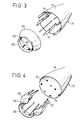
- FIGS. 3 and 4 show the implementation of longitudinal partitions 61, 72 ensuring guiding of the diffuser 20 relative to the divergent 14.
- FIGS. 3 and 4 which are exploded views showing the diffuser 20 separated from the divergent 14 , relate to a diffuser 20 with a neck 25, but partitions 61, 72 could similarly be installed in an embodiment with a frustoconical diffuser 50.
- FIG. 3 shows partitions or ribs 61 which are arranged longitudinally and fixed on the downstream part of the internal face of the diverging part 14.
- the ribs 61 which are regularly distributed around the periphery of the diverging part 14 and can for example be 6 in number to 12, project beyond the downstream end 15 of the diverging portion 14 to penetrate inside the diffuser 20 and engage in corresponding grooves 62 formed on the internal face of the diffuser.
- the ribs 61 serve both to stiffen the divergent, to strengthen the connection between the diffuser 20 and the divergent 14, to guide the diffuser 20 during its ejection, and to limit the recirculation of hot gases.
- Figure 4 shows an embodiment very similar to that of Figure 3, but in which ribs or partitions 72 are integral with the diffuser 20 and project upstream of this diffuser to penetrate corresponding grooves 71 formed in the downstream part of the internal face of the divergent 14.
- the ribs 72 of FIG. 4 play exactly the same role as the ribs 61 of FIG. 3.
- FIGS. 6 and 7 show a particular example of connection 80 between a diffuser 50, represented in the form of a frustoconical diffuser but which could also be a diffuser 20 with a neck, and the downstream end 15 of a divergent 14.
- the connecting means 80 are provided to be broken after a predetermined operating time when the rocket engine has reached a sufficient altitude for which the external pressure is reduced. Upon rupture of the connecting means 80, this diffuser is separated from the diverging part 14 and ejected.
- connection means 80 can be broken by a remote control using pyrotechnic, pneumatic or electric means.
- pyrotechnic pneumatic or electric means.
- the control of the rupture of the connecting means 80 can also intervene automatically after a predetermined time, for example of the order of several tens of seconds, thanks to the use of a locking element made for example of abradable composite material .
- the control of the rupture of the connection means 80 can thus be of the active or passive type.
- a vaporizable foam can be added to the diffuser 20 or 50 in order to cool explosive bolts for a predetermined time until the moment of ordering the rupture of the connection means 80.
- connection means 80 in FIGS. 6 and 7, we see the downstream end 15 of the diverging portion 14 which is provided with a flange 15a while the upstream end of the diffuser 50 itself has a flange 92.
- the flanges 15a and 92 are held by jumpers 81 articulated around axes 82 mounted on yokes 16 formed at the downstream end of the diverging part 14.
- Each rider or stirrup 81 can comprise a hook 83 engaged under the flange 92 and an external tongue 84 provided with a groove receiving a cable 85 which surrounds the downstream end of the diverging part 14 and is connected to a system 86 for tensioning and unlocking.
- a system 86 for tensioning and unlocking.
- the downstream end 51 of the diffuser 50 (FIG. 6) can retain a hoop 88 ensuring the mechanical maintenance of the various parts.
Landscapes
- Engineering & Computer Science (AREA)
- Chemical & Material Sciences (AREA)
- Combustion & Propulsion (AREA)
- Mechanical Engineering (AREA)
- General Engineering & Computer Science (AREA)
- Jet Pumps And Other Pumps (AREA)
Claims (10)
- Raketendüse mit abwerfbarem Diffusor für die erste Trägerraketenstufe, mit einem konvergierenden Abschnitt (12), der die Gase, die in einer Brennkammer (13) erzeugt werden, aufnimmt, einem Düsenhals (11) mit verringertem Querschnitt (So) und einem divergierenden Abschnitt (14), der mit dem Düsenhals (11) verbunden ist und in seinem stromabwärts gelegenen Abschnitt (15) in einem Gas-Austrittsquerschnitt (Se) endet, der ein erhöhtes Querschnittsverhältnis (ε = Se/So) festlegt, das größer als etwa 50 ist,
dadurch gekennzeichnet, daß der divergierende Abschnitt (14) in seinem stromabwärts gelegenen Teil um einen abwerfbaren Diffusor (20; 50) verlängert ist, der stromabwärts von dem Bereich der Verbindung mit dem divergierenden Abschnitt (14) eine Zone (25; 51) mit verringertem Querschnitt (S1) aufweist, um in einer ersten Flugphase bei Vorliegen eines beträchtlichen Außendrucks eine erneute Verdichtung der Strömung heißer Gase sicherzustellen und das Auftreten einer Strömungsablösung längs der Wand des divergierenden Abschnitts zu verhindern. - Düse nach Anspruch 1, dadurch gekennzeichnet, daß der Querschnitt (S1) der Zone (25; 51) des Diffusors (20; 50) mit verringertem Querschnitt in der Größenordnung von 15 bis 45% des Austrittsquerschnitts (Se) des divergierenden Abschnitts (14) liegt.
- Düse nach Anspruch 1 oder Anspruch 2, dadurch gekennzeichnet, daß der abwerfbare Diffusor (50) eine im wesentlichen kegelstumpfförmige Gestalt aufweist, mit einem Neigungswinkel (α), der kleiner oder gleich ist etwa 20° in Bezug auf eine Richtung parallel zur Düsenachse.
- Düse nach Anspruch 1 oder Anspruch 2, dadurch gekennzeichnet, daß der abwerfbare Diffusor (20) einen profilierten Hals (25) aufweist, der die genannte Zone mit verringertem Querschnitt (S1) bildet.
- Düse nach irgendeinem der Ansprüche 1 bis 4, dadurch gekennzeichnet, daß der abwerfbare Diffusor (20; 50) aus mehreren Teilen (21 bis 24) gebildet ist.
- Düse nach irgendeinem der Ansprüche 1 bis 5, dadurch gekennzeichnet, daß der divergierende Abschnitt (14) auf seiner Innenfläche Längsrippen (61) aufweist, die sich über das stromabwärtsgelegene Ende verlängern und mit Längsrillen (62) zusammenwirken, die auf der Innenfläche des abwerfbaren Diffusors (20; 50) ausgebildet sind.
- Düse nach irgendeinem der Ansprüche 1 bis 5, dadurch gekennzeichnet, daß der abwerfbare Diffusor (20; 50) auf seiner Innenfläche Längsrippen (72) aufweist, die sich über das stromaufwärtsgelegene Ende des Diffusors verlängern und mit Längsrillen (71) zusammenwirken, die auf der Innenfläche des divergierenden Abschnitts (14) ausgebildet sind.
- Düse nach irgendeinem der Ansprüche 1 bis 7, dadurch gekennzeichnet, daß der abwerfbare Diffusor (20; 50) wahlweise betätigbare Mittel (80) zur Verbindung mit dem stromabwärts gelegenen Ende (15) des divergierenden Abschnitts (14) aufweist, und daß das Auseinandertrennen dieser Mittel (80) zur Verbindung ferngesteuert ist.
- Düse nach irgendeinem der Ansprüche 1 bis 7, dadurch gekennzeichnet, daß die Mittel (80) zur Verbindung zwischen dem abwerfbaren Diffusor (20; 50) und dem stromabwärtsgelegenen Ende (15) des divergierenden Abschnitts (14) Mittel aufweisen, die derart ausgebildet sind, daß sie sich automatisch nach einer vorbestimmten Funktionsdauer auseinandertrennen.
- Düse nach irgendeinem der Ansprüche 1 bis 7, dadurch gekennzeichnet, daß die Mittel (80) zur Verbindung zwischen dem abwerfbaren Diffusor (20; 50) und dem stromabwärtsgelegenen Ende (15) des divergierenden Abschnitts (14) eine Gruppe gelenkig gelagerter Bügel (81) aufweisen, die Flansche (15a, 92)) zusammenklemmen, die an den in Berührung stehenden Enden des divergierenden Abschnitts (14) und des abwerfbaren Diffusors (20; 50) ausgebildet sind, sowie ein Haltesystem (85, 86) für die Bügel, das mit Entriegelungsmitteln ausgestattet ist, die wahlweise angesteuert werden, um den Abwurf des Diffusors (20; 50) zu gestatten, wenn die Gefahr der Ablösung des Gasstrahls im Inneren des divergierenden Abschnitts (14) verschwunden ist.
Applications Claiming Priority (2)
| Application Number | Priority Date | Filing Date | Title |
|---|---|---|---|
| FR9306454A FR2705738B1 (fr) | 1993-05-28 | 1993-05-28 | Tuyère de moteur-fusée à diffuseur éjectable. |
| FR9306454 | 1993-05-28 |
Publications (2)
| Publication Number | Publication Date |
|---|---|
| EP0632197A1 EP0632197A1 (de) | 1995-01-04 |
| EP0632197B1 true EP0632197B1 (de) | 1997-07-30 |
Family
ID=9447570
Family Applications (1)
| Application Number | Title | Priority Date | Filing Date |
|---|---|---|---|
| EP94401179A Expired - Lifetime EP0632197B1 (de) | 1993-05-28 | 1994-05-27 | Raketendüse mit abwerfbarem Diffusor |
Country Status (4)
| Country | Link |
|---|---|
| US (1) | US5490629A (de) |
| EP (1) | EP0632197B1 (de) |
| DE (1) | DE69404568T2 (de) |
| FR (1) | FR2705738B1 (de) |
Families Citing this family (9)
| Publication number | Priority date | Publication date | Assignee | Title |
|---|---|---|---|---|
| US5779151A (en) * | 1996-05-28 | 1998-07-14 | Regents Of The University Of California | Stepped nozzle |
| FR2754566B1 (fr) * | 1996-10-11 | 1999-02-05 | Europ Propulsion | Tuyere de moteur-fusee a inserts ejectables |
| US6330793B1 (en) | 1999-07-02 | 2001-12-18 | Atlantic Research Corporation | Erosion resistant rocket nozzle |
| RU2175727C2 (ru) * | 1999-12-07 | 2001-11-10 | Открытое акционерное общество Научно-производственное объединение "Искра" | Твердотопливный двигатель с отделяемым сопловым блоком |
| FR2816990B1 (fr) * | 2000-11-22 | 2003-02-21 | Snecma Moteurs | Dispositif de reduction ou suppression de decollement de jet dans les tuyeres de moteur-fusee et tuyere comprenant le dispositif |
| US7946104B2 (en) * | 2006-05-12 | 2011-05-24 | Rohr, Inc. | Bleed air relief system for engines |
| FR2975730B1 (fr) * | 2011-05-23 | 2013-06-21 | Snecma | Systeme de reduction de la dynamique du segment mobile d'une tuyere deployable pour moteur de fusee |
| WO2017222908A1 (en) * | 2016-06-21 | 2017-12-28 | Aerojet Rocketdyne, Inc. | Liquid propellant rocket engine with passive condensate cooling |
| US11585296B1 (en) * | 2020-01-14 | 2023-02-21 | Herbert U. Fluhler | Self compensating rocket engine enhancement |
Family Cites Families (11)
| Publication number | Priority date | Publication date | Assignee | Title |
|---|---|---|---|---|
| US2880576A (en) * | 1954-05-25 | 1959-04-07 | Peter G Kappus | Supersonic variable throat nozzle |
| US2937494A (en) * | 1955-09-13 | 1960-05-24 | Johnson Horace James | Series type multiple thermal jet propulsion system |
| US3237402A (en) * | 1963-11-14 | 1966-03-01 | Steverding Bernard | Variable thrust nozzle |
| US3357658A (en) * | 1965-09-08 | 1967-12-12 | Northrop Corp | Peripheral jet rocket engine |
| US3925982A (en) * | 1973-09-11 | 1975-12-16 | Martin Marietta Corp | Fluid-dynamic shock ring for controlled flow separation in a rocket engine exhaust nozzle |
| US4077572A (en) * | 1976-03-25 | 1978-03-07 | Chandler Evans Inc. | Reduced size altitude insensitive thrust vector control nozzle |
| FR2457390A1 (fr) * | 1979-05-23 | 1980-12-19 | Europ Propulsion | Divergent deployable de tuyere pour propulseur fusee |
| FR2503794B1 (fr) * | 1981-04-13 | 1986-04-25 | Europ Propulsion | Chambre de combustion de propulseur-fusee a divergent multiple |
| DE3427169C2 (de) * | 1984-07-24 | 1987-04-30 | Messerschmitt-Bölkow-Blohm GmbH, 8012 Ottobrunn | Raketentriebwerk für Raumflüge |
| FR2618488B1 (fr) * | 1987-07-20 | 1989-12-15 | Europ Propulsion | Divergent a rupture de galbe pour tuyere de moteur-fusee |
| US7925982B2 (en) * | 2006-09-01 | 2011-04-12 | Cheryl Parker | System and method of overlaying and integrating data with geographic mapping applications |
-
1993
- 1993-05-28 FR FR9306454A patent/FR2705738B1/fr not_active Expired - Fee Related
-
1994
- 1994-05-25 US US08/248,968 patent/US5490629A/en not_active Expired - Lifetime
- 1994-05-27 EP EP94401179A patent/EP0632197B1/de not_active Expired - Lifetime
- 1994-05-27 DE DE69404568T patent/DE69404568T2/de not_active Expired - Fee Related
Also Published As
| Publication number | Publication date |
|---|---|
| DE69404568T2 (de) | 1998-01-29 |
| US5490629A (en) | 1996-02-13 |
| DE69404568D1 (de) | 1997-09-04 |
| EP0632197A1 (de) | 1995-01-04 |
| FR2705738B1 (fr) | 1995-08-18 |
| FR2705738A1 (fr) | 1994-12-02 |
Similar Documents
| Publication | Publication Date | Title |
|---|---|---|
| FR2987081A1 (fr) | Ensemble et procede propulsifs | |
| EP1731839A2 (de) | Vorrichtung zum Anbringen einer Einspritzungvorrichtung am Boden einer Turbinenbrennkammer und Verfahren zum Anbringen | |
| EP0626512B1 (de) | Raketendüse mit ausgezacktem Austrittkonus | |
| FR2618488A1 (fr) | Divergent a rupture de galbe pour tuyere de moteur-fusee | |
| EP0632197A1 (de) | Raketendüse mit abwerfbarem Diffusor | |
| EP1884649A1 (de) | Mantelstromtriebwerk mit variablem engsten Querschnitt mittels Luft-Einspritzung | |
| CA2743009A1 (fr) | Entree d'air d'un moteur d'avion a helices propulsives non carenees | |
| EP0626513B1 (de) | Raketendüse mit selektiv reduziertem Austrittsquerschnitt | |
| FR2549146A1 (fr) | Ensemble propulsif pour missile statoreacteur a propulseur d'acceleration integre | |
| FR2857415A1 (fr) | Tuyere de moteur a turbine | |
| EP0836001B1 (de) | Raketendüse mit abwerfbarem Einsatz | |
| FR2731471A1 (fr) | Moteur-fusee a propergol solide avec charges propulsives a combustion exterieure et a combustion interieure | |
| WO2018100274A1 (fr) | Système correcteur d'effet pogo | |
| WO2017013341A1 (fr) | Dispositif de modulation de section d'éjection de gaz | |
| FR3052191B1 (fr) | Inversion de poussee dans une turbomachine avec soufflante a calage variable | |
| EP3781805B1 (de) | System zur steuerung des geschwindigkeitswechselns und der schubvektorisierung in einer mehrformdüse durch sekundäre einspritzung | |
| EP3507195B1 (de) | Raketenmotor mit einer sicherungsvorrichtung | |
| EP2715100B1 (de) | System zur reduzierung der dynamik des mobilen abschnitts einer entfaltbaren raketenmotordüse | |
| EP1209344B1 (de) | Raketendüse | |
| EP3095716B1 (de) | Versorgungs-anschlussmodul für trägerrakete | |
| EP2623918B1 (de) | Pneumatische abschussvorrichtung | |
| EP3426906B1 (de) | Raketenantrieb mit bodenzündung | |
| FR2907853A1 (fr) | Tuyere d'ejection des gaz pour turbomachine a double flux ayant une section d'ejection ou de col variable par deploiement de creneaux | |
| WO2021140053A1 (fr) | Tuyère à section de sortie variable pour moteur de fusée et moteur de fusée comportant une telle tuyère | |
| FR2981134A1 (fr) | Dispositif avec paroi avec au moins deux ouvertures debouchant dans un flux de gaz |
Legal Events
| Date | Code | Title | Description |
|---|---|---|---|
| PUAI | Public reference made under article 153(3) epc to a published international application that has entered the european phase |
Free format text: ORIGINAL CODE: 0009012 |
|
| AK | Designated contracting states |
Kind code of ref document: A1 Designated state(s): DE SE |
|
| 17P | Request for examination filed |
Effective date: 19950607 |
|
| GRAG | Despatch of communication of intention to grant |
Free format text: ORIGINAL CODE: EPIDOS AGRA |
|
| 17Q | First examination report despatched |
Effective date: 19960927 |
|
| GRAH | Despatch of communication of intention to grant a patent |
Free format text: ORIGINAL CODE: EPIDOS IGRA |
|
| GRAH | Despatch of communication of intention to grant a patent |
Free format text: ORIGINAL CODE: EPIDOS IGRA |
|
| GRAA | (expected) grant |
Free format text: ORIGINAL CODE: 0009210 |
|
| AK | Designated contracting states |
Kind code of ref document: B1 Designated state(s): DE SE |
|
| REF | Corresponds to: |
Ref document number: 69404568 Country of ref document: DE Date of ref document: 19970904 |
|
| PLBE | No opposition filed within time limit |
Free format text: ORIGINAL CODE: 0009261 |
|
| STAA | Information on the status of an ep patent application or granted ep patent |
Free format text: STATUS: NO OPPOSITION FILED WITHIN TIME LIMIT |
|
| 26N | No opposition filed | ||
| PGFP | Annual fee paid to national office [announced via postgrant information from national office to epo] |
Ref country code: DE Payment date: 20080514 Year of fee payment: 15 |
|
| PGFP | Annual fee paid to national office [announced via postgrant information from national office to epo] |
Ref country code: SE Payment date: 20080425 Year of fee payment: 15 |
|
| PG25 | Lapsed in a contracting state [announced via postgrant information from national office to epo] |
Ref country code: DE Free format text: LAPSE BECAUSE OF NON-PAYMENT OF DUE FEES Effective date: 20091201 |
|
| PG25 | Lapsed in a contracting state [announced via postgrant information from national office to epo] |
Ref country code: SE Free format text: LAPSE BECAUSE OF NON-PAYMENT OF DUE FEES Effective date: 20090528 |