EP0632245B1 - Echangeur de chaleur eau-air en aluminium pour véhicules automobiles - Google Patents
Echangeur de chaleur eau-air en aluminium pour véhicules automobiles Download PDFInfo
- Publication number
- EP0632245B1 EP0632245B1 EP94110227A EP94110227A EP0632245B1 EP 0632245 B1 EP0632245 B1 EP 0632245B1 EP 94110227 A EP94110227 A EP 94110227A EP 94110227 A EP94110227 A EP 94110227A EP 0632245 B1 EP0632245 B1 EP 0632245B1
- Authority
- EP
- European Patent Office
- Prior art keywords
- flat
- heat exchanger
- partition
- tube
- exchanger according
- Prior art date
- Legal status (The legal status is an assumption and is not a legal conclusion. Google has not performed a legal analysis and makes no representation as to the accuracy of the status listed.)
- Expired - Lifetime
Links
Images

Classifications
-
- F—MECHANICAL ENGINEERING; LIGHTING; HEATING; WEAPONS; BLASTING
- F28—HEAT EXCHANGE IN GENERAL
- F28F—DETAILS OF HEAT-EXCHANGE AND HEAT-TRANSFER APPARATUS, OF GENERAL APPLICATION
- F28F3/00—Plate-like or laminated elements; Assemblies of plate-like or laminated elements
- F28F3/02—Elements or assemblies thereof with means for increasing heat-transfer area, e.g. with fins, with recesses, with corrugations
- F28F3/04—Elements or assemblies thereof with means for increasing heat-transfer area, e.g. with fins, with recesses, with corrugations the means being integral with the element
- F28F3/042—Elements or assemblies thereof with means for increasing heat-transfer area, e.g. with fins, with recesses, with corrugations the means being integral with the element in the form of local deformations of the element
- F28F3/044—Elements or assemblies thereof with means for increasing heat-transfer area, e.g. with fins, with recesses, with corrugations the means being integral with the element in the form of local deformations of the element the deformations being pontual, e.g. dimples
-
- B—PERFORMING OPERATIONS; TRANSPORTING
- B60—VEHICLES IN GENERAL
- B60H—ARRANGEMENTS OF HEATING, COOLING, VENTILATING OR OTHER AIR-TREATING DEVICES SPECIALLY ADAPTED FOR PASSENGER OR GOODS SPACES OF VEHICLES
- B60H1/00—Heating, cooling or ventilating devices
- B60H1/00321—Heat exchangers for air-conditioning devices
- B60H1/00328—Heat exchangers for air-conditioning devices of the liquid-air type
-
- F—MECHANICAL ENGINEERING; LIGHTING; HEATING; WEAPONS; BLASTING
- F28—HEAT EXCHANGE IN GENERAL
- F28D—HEAT-EXCHANGE APPARATUS, NOT PROVIDED FOR IN ANOTHER SUBCLASS, IN WHICH THE HEAT-EXCHANGE MEDIA DO NOT COME INTO DIRECT CONTACT
- F28D1/00—Heat-exchange apparatus having stationary conduit assemblies for one heat-exchange medium only, the media being in contact with different sides of the conduit wall, in which the other heat-exchange medium is a large body of fluid, e.g. domestic or motor car radiators
- F28D1/02—Heat-exchange apparatus having stationary conduit assemblies for one heat-exchange medium only, the media being in contact with different sides of the conduit wall, in which the other heat-exchange medium is a large body of fluid, e.g. domestic or motor car radiators with heat-exchange conduits immersed in the body of fluid
- F28D1/03—Heat-exchange apparatus having stationary conduit assemblies for one heat-exchange medium only, the media being in contact with different sides of the conduit wall, in which the other heat-exchange medium is a large body of fluid, e.g. domestic or motor car radiators with heat-exchange conduits immersed in the body of fluid with plate-like or laminated conduits
- F28D1/0308—Heat-exchange apparatus having stationary conduit assemblies for one heat-exchange medium only, the media being in contact with different sides of the conduit wall, in which the other heat-exchange medium is a large body of fluid, e.g. domestic or motor car radiators with heat-exchange conduits immersed in the body of fluid with plate-like or laminated conduits the conduits being formed by paired plates touching each other
- F28D1/035—Heat-exchange apparatus having stationary conduit assemblies for one heat-exchange medium only, the media being in contact with different sides of the conduit wall, in which the other heat-exchange medium is a large body of fluid, e.g. domestic or motor car radiators with heat-exchange conduits immersed in the body of fluid with plate-like or laminated conduits the conduits being formed by paired plates touching each other with U-flow or serpentine-flow inside the conduits
-
- F—MECHANICAL ENGINEERING; LIGHTING; HEATING; WEAPONS; BLASTING
- F28—HEAT EXCHANGE IN GENERAL
- F28D—HEAT-EXCHANGE APPARATUS, NOT PROVIDED FOR IN ANOTHER SUBCLASS, IN WHICH THE HEAT-EXCHANGE MEDIA DO NOT COME INTO DIRECT CONTACT
- F28D1/00—Heat-exchange apparatus having stationary conduit assemblies for one heat-exchange medium only, the media being in contact with different sides of the conduit wall, in which the other heat-exchange medium is a large body of fluid, e.g. domestic or motor car radiators
- F28D1/02—Heat-exchange apparatus having stationary conduit assemblies for one heat-exchange medium only, the media being in contact with different sides of the conduit wall, in which the other heat-exchange medium is a large body of fluid, e.g. domestic or motor car radiators with heat-exchange conduits immersed in the body of fluid
- F28D1/03—Heat-exchange apparatus having stationary conduit assemblies for one heat-exchange medium only, the media being in contact with different sides of the conduit wall, in which the other heat-exchange medium is a large body of fluid, e.g. domestic or motor car radiators with heat-exchange conduits immersed in the body of fluid with plate-like or laminated conduits
- F28D1/0391—Heat-exchange apparatus having stationary conduit assemblies for one heat-exchange medium only, the media being in contact with different sides of the conduit wall, in which the other heat-exchange medium is a large body of fluid, e.g. domestic or motor car radiators with heat-exchange conduits immersed in the body of fluid with plate-like or laminated conduits a single plate being bent to form one or more conduits
-
- F—MECHANICAL ENGINEERING; LIGHTING; HEATING; WEAPONS; BLASTING
- F28—HEAT EXCHANGE IN GENERAL
- F28F—DETAILS OF HEAT-EXCHANGE AND HEAT-TRANSFER APPARATUS, OF GENERAL APPLICATION
- F28F9/00—Casings; Header boxes; Auxiliary supports for elements; Auxiliary members within casings
- F28F9/02—Header boxes; End plates
- F28F9/04—Arrangements for sealing elements into header boxes or end plates
- F28F9/16—Arrangements for sealing elements into header boxes or end plates by permanent joints, e.g. by rolling
- F28F9/18—Arrangements for sealing elements into header boxes or end plates by permanent joints, e.g. by rolling by welding
- F28F9/182—Arrangements for sealing elements into header boxes or end plates by permanent joints, e.g. by rolling by welding the heat-exchange conduits having ends with a particular shape, e.g. deformed; the heat-exchange conduits or end plates having supplementary joining means, e.g. abutments
-
- F—MECHANICAL ENGINEERING; LIGHTING; HEATING; WEAPONS; BLASTING
- F28—HEAT EXCHANGE IN GENERAL
- F28F—DETAILS OF HEAT-EXCHANGE AND HEAT-TRANSFER APPARATUS, OF GENERAL APPLICATION
- F28F9/00—Casings; Header boxes; Auxiliary supports for elements; Auxiliary members within casings
- F28F9/26—Arrangements for connecting different sections of heat-exchange elements, e.g. of radiators
- F28F9/262—Arrangements for connecting different sections of heat-exchange elements, e.g. of radiators for radiators
-
- F—MECHANICAL ENGINEERING; LIGHTING; HEATING; WEAPONS; BLASTING
- F28—HEAT EXCHANGE IN GENERAL
- F28D—HEAT-EXCHANGE APPARATUS, NOT PROVIDED FOR IN ANOTHER SUBCLASS, IN WHICH THE HEAT-EXCHANGE MEDIA DO NOT COME INTO DIRECT CONTACT
- F28D1/00—Heat-exchange apparatus having stationary conduit assemblies for one heat-exchange medium only, the media being in contact with different sides of the conduit wall, in which the other heat-exchange medium is a large body of fluid, e.g. domestic or motor car radiators
- F28D1/02—Heat-exchange apparatus having stationary conduit assemblies for one heat-exchange medium only, the media being in contact with different sides of the conduit wall, in which the other heat-exchange medium is a large body of fluid, e.g. domestic or motor car radiators with heat-exchange conduits immersed in the body of fluid
- F28D1/04—Heat-exchange apparatus having stationary conduit assemblies for one heat-exchange medium only, the media being in contact with different sides of the conduit wall, in which the other heat-exchange medium is a large body of fluid, e.g. domestic or motor car radiators with heat-exchange conduits immersed in the body of fluid with tubular conduits
- F28D1/053—Heat-exchange apparatus having stationary conduit assemblies for one heat-exchange medium only, the media being in contact with different sides of the conduit wall, in which the other heat-exchange medium is a large body of fluid, e.g. domestic or motor car radiators with heat-exchange conduits immersed in the body of fluid with tubular conduits the conduits being straight
- F28D1/0535—Heat-exchange apparatus having stationary conduit assemblies for one heat-exchange medium only, the media being in contact with different sides of the conduit wall, in which the other heat-exchange medium is a large body of fluid, e.g. domestic or motor car radiators with heat-exchange conduits immersed in the body of fluid with tubular conduits the conduits being straight the conduits having a non-circular cross-section
- F28D1/05366—Assemblies of conduits connected to common headers, e.g. core type radiators
- F28D1/05391—Assemblies of conduits connected to common headers, e.g. core type radiators with multiple rows of conduits or with multi-channel conduits combined with a particular flow pattern, e.g. multi-row multi-stage radiators
-
- F—MECHANICAL ENGINEERING; LIGHTING; HEATING; WEAPONS; BLASTING
- F28—HEAT EXCHANGE IN GENERAL
- F28D—HEAT-EXCHANGE APPARATUS, NOT PROVIDED FOR IN ANOTHER SUBCLASS, IN WHICH THE HEAT-EXCHANGE MEDIA DO NOT COME INTO DIRECT CONTACT
- F28D21/00—Heat-exchange apparatus not covered by any of the groups F28D1/00 - F28D20/00
- F28D2021/0019—Other heat exchangers for particular applications; Heat exchange systems not otherwise provided for
- F28D2021/008—Other heat exchangers for particular applications; Heat exchange systems not otherwise provided for for vehicles
- F28D2021/0091—Radiators
- F28D2021/0094—Radiators for recooling the engine coolant
-
- F—MECHANICAL ENGINEERING; LIGHTING; HEATING; WEAPONS; BLASTING
- F28—HEAT EXCHANGE IN GENERAL
- F28D—HEAT-EXCHANGE APPARATUS, NOT PROVIDED FOR IN ANOTHER SUBCLASS, IN WHICH THE HEAT-EXCHANGE MEDIA DO NOT COME INTO DIRECT CONTACT
- F28D21/00—Heat-exchange apparatus not covered by any of the groups F28D1/00 - F28D20/00
- F28D2021/0019—Other heat exchangers for particular applications; Heat exchange systems not otherwise provided for
- F28D2021/008—Other heat exchangers for particular applications; Heat exchange systems not otherwise provided for for vehicles
- F28D2021/0091—Radiators
- F28D2021/0096—Radiators for space heating
-
- F—MECHANICAL ENGINEERING; LIGHTING; HEATING; WEAPONS; BLASTING
- F28—HEAT EXCHANGE IN GENERAL
- F28F—DETAILS OF HEAT-EXCHANGE AND HEAT-TRANSFER APPARATUS, OF GENERAL APPLICATION
- F28F1/00—Tubular elements; Assemblies of tubular elements
- F28F1/02—Tubular elements of cross-section which is non-circular
- F28F2001/027—Tubular elements of cross-section which is non-circular with dimples
Definitions
- the invention relates to a water / air heat exchanger made of aluminum or an aluminum alloy for motor vehicles, in particular to a heating heat exchanger or engine cooler, according to the preamble of claim 1.
- a heat exchanger is known from JP-A-32 38 165.
- the alloys AlMnl or AlMgSi or A199.5 are particularly suitable as aluminum alloys for such heat exchangers, the former two alloys preferably being used for pipes, water boxes and plates and the latter alloy preferably being used for zigzag fins.
- Pipes and water boxes are appropriately pre-coated on both sides with hard solder AlSi7.
- This solder coating is applied with flux, e.g. sprayed a sodium fluoride and potassium aluminum fluoride.
- the soldering to the end product, which is protected according to the invention, is then carried out in a soldering furnace under protective gas without the addition of further solder to the precoating.
- Water / air heat exchangers such as engine coolers or in particular heating heat exchangers, to which the invention is based in particular, are also heat exchangers which, in contrast to evaporators or condensers in a cooling circuit be arranged within a motor vehicle.
- a cooling circuit uses water or water with an anti-freeze additive such as glycol as the internal heat exchange medium.
- the ambient air serves as the external heat exchange medium.
- Such water / air heat exchangers for motor vehicles are thus operated at a relatively low internal pressure, specifically at an operating pressure of approximately 1.5 to at most 2 bar and an inlet pressure of in particular 4 bar.
- evaporators and condensers of air conditioning systems in motor vehicles have a non-water-based coolant, for example the fluorochlorohydrocarbons now now considered to be environmentally harmful or now fluorocarbons, and must be designed for high internal operating pressures, such as typically operating pressures of about 25 bar and burst pressures of over 100 bar (e.g. 105 bar).
- the design criteria of heat exchangers according to the invention and of evaporators and condensers in motor vehicles are therefore fundamentally different from the outset because of the different strength requirements.
- water / air heat exchangers for motor vehicles are large-scale products, although a large motor vehicle manufacturer can already produce quantities of around half a million to well over one million per year in a single type of car. Large-scale products of this type therefore have the character of mass-produced items, in which small cost savings are of great importance in the context of the cost optimization that is always demanded from the motor vehicle manufacturers, especially since, within the scope of such optimization work, no compromises should be made with regard to the optimal functionality at the same time.
- heat exchangers for motor vehicles put together from aluminum pipes and water boxes made of plastic have been preferred for cost reasons, since the known heat exchangers made of all-aluminum, ie including the aluminum water box, because of the various complex ones Steps in soldering were more expensive to manufacture, although the additional cost was only justifiable due to the recyclability.
- the material of the lid of the water tank should initially remain open in a heat exchanger which is referred to as consisting of aluminum (or an aluminum alloy), so that this lid may continue to be made of plastic and can be dismantled before the recycling process .
- the tube sheet is made of aluminum or an aluminum alloy.
- the possibility known per se in heat exchangers on the market is also included, also to manufacture the water tank completely from aluminum, so that its tube sheet and its Lids are both made of aluminum or an aluminum alloy and are brazed together.
- the water / air heat exchangers to which the invention relates are operated in cross-countercurrent. At least double-flow heat exchangers are required for such operation in cross-counterflow. In this case, however, it is also possible to connect two-row and multi-row or in particular two-port and multiple-flow heat exchangers in parallel with lower flow requirements and then operate them only in a single cross flow. In the context of the invention, such a structure, which would also be included in the borderline case, would then strictly speaking not be multi-flow, but only multi-row. As mentioned, however, reference is made in the context of the invention in particular to real multi-flow.
- the flat tubes themselves with at least one partition wall running in the longitudinal direction, the partition wall in each case between adjacent opposing floods in a connection area at the Water tank distant ends of the flat tubes is recessed over a length, along which the neighboring opposing floods communicate.
- the partition wall which only extends over a limited length of the flat tube, is subsequently inserted into the flat tube body, be it as a simple partition wall fixed by retaining knobs, or as a partition wall in combination with turbulence-generating arms, which at the same time serve for centering in the flat tubes.
- This method of production is also cumbersome and expensive in view of the narrow clear widths of the flat tubes.
- the partition wall is formed by deforming the sheet metal part forming the flat tube, by forming a bead up to the opposite wall.
- the entire flat tube is already formed from a single sheet metal part, the partition wall itself being formed by deforming this sheet metal part .
- both ends of the sheet metal part are bent so that together they produce a double-walled form of the partition.
- the connection area of the opposing floods is created by a cutout in the sheet metal part.
- the solder gap length is practically zero. But if the cut in the connection area is chosen so that there is still some soldering gap, it is inevitably very small in the context of this known construction.
- turbulence can occur in the connection area due to the construction of the double-walled partition and its connection to the inner wall surfaces of the flat sides of the flat tube.
- the invention is therefore based on the object of further optimizing a heat exchanger of the generic type, both in terms of cost and function, with minimal use of material, special emphasis being placed on the lowest possible resistance on the heating medium with the highest possible internal heat transfer coefficient and neither during the soldering process nor during operation by the Construction faults should occur.
- the supporting indentations provided according to the invention according to the second characteristic feature not only have the usual function as turbulators, but also complement the support of the two flat sides against one another in such a way that the single wall of the partition wall no longer plays a role with regard to the dimensional stability, but the support function is even overcompensated .
- the type of formation of the partition wall with a flush overlap with the areas of the flat sides of the flat tubes that continue in the region of the partition wall also offers the advantage that, even in the area of the connection area where the two flows of the flat tube adjoin one another, soldering can take place over a sufficiently long soldering path, which can be freely selected by choosing the length of the overlap area.
- the indentations act as such turbulators, which are specifically designed for the narrow flat tubes that occur in practice, while turbulence inserts, such as those used in DE-C2- 3 440 489, hardly even with narrow flat tubes, even according to their own statements in this prior publication have a turbulent meaning.
- the high pressure stability of the heat exchanger according to the invention is particularly important, particularly in the case of heating heat exchangers for motor vehicles, which are positioned in the vehicle interior and which are supposed to be more stable against internal burst pressure than an engine cooler which is switched on in the same circuit.
- an external flux access for soldering the partition of the respective flat tube is then expediently provided to enable the soldering, which is closed after the soldering by the solder, wherein this external flux access can be provided in the area of an overlap in the area of the flush connections on both sides, without having to form a separate flux window in certain applications.
- such a window is preferably additionally created by forming guide channels for flux in the sheet metal part in the overlap region along the overlap distance.
- a cutout can be formed, for example punched out, in the connection area of the communication between the two floods, which is exact there corresponds to the clear internal cross section of the flat tube. Since the flat tube is flush on the outside in this area, but is double-walled due to the overlap, a throttling restriction of one wall thickness of the flat tube is obtained on each side of the flat tube. Because of the way of production, bent back beads do not have to be reverted to, as was the case in DE-C2-3 440 489. One can also avoid the asymmetry of the known case due to the bending only in one direction.
- a further development according to claim 11 is preferred, in which, in the connection area for communicating the opposing floods, the sheet metal part is cut out not only as a continuation of the partition, but also subsequently, preferably on both sides, along a partial section of its overlap.
- the influence of double wall thickness in the overlap area on the resistance coefficient can be made less effective in the connection area, so that there is practically only a reduction in communication by one wall thickness of the flat tube.
- the upper limit of the narrowing of the communication in the connection area of the opposing floods can preferably also be reduced to approximately a wall thickness of the flat tube.
- the boundary of the cut-out then runs obliquely, preferably at an angle ⁇ of 30 ° to 60 ° with respect to the planes of the flat sides of the flat tube, a further reduction in the drag coefficient is obtained by good flow transitions on the inner wall surface of the flat tube.
- the bundle of flat tubes and zigzag fins is held in the base plate of the water box at one end of the flat tubes.
- the ends of the flat tubes remote from the water box are soldered into grooves in an end plate.
- the end of the flat tubes is brought about at the end of their connection area for the communication of the opposing floods.
- the end plate can also be used as a flange for receiving the heat exchanger in a holding housing in the motor vehicle.
- the package of flat tubes and zigzag fins is expediently held between side plates and soldered to them.
- the side plates then engage in a form-fitting manner in holding recesses in the tube sheet of the water tank and the end plate soldered.
- the package of flat tubes and zigzag fins is edged between the two side plates. Then the side plates are moved towards each other until the arrangement of the flat tubes corresponds to the division in the tube sheet. Then, on one side of the water box and on the other side, the end plate can be pressed on and latched in, the side plates serving as an axial spacer between the water box and the end plate. After such a latching process, the package that has not yet been soldered can be transferred to the soldering furnace in the correct mutual position without the need for other holding aids and soldered there.
- the wall indentations are preferably provided in a grid of points, even in order to dent the solder connection points on the zigzag fins as little as possible on the outside and thus to create the largest possible contact surface of the outside of the flat tube with the zigzag fins.
- This effect can be improved if the grid, be it only a point grid or another, is oriented at an angle deviating from 90 °, preferably from 3 ° to 20 °, with respect to the axis of the respective flat tube. This makes it possible to ensure that the flat individual slats do not match the continuation direction of the grid.
- the flat tube in which the flat tube is formed from a sheet metal part by folding, it makes sense to precoat the sheet metal part on both sides with solder.
- This two-sided pre-coating also serves, for example, to solder the indentations to one another on the inside and to the outside to solder the zigzag lamellae and in the slot in the tube sheet.
- An aluminum hard solder as in general is also possible as a solder.
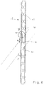
- the double-flow heat exchanger according to FIG. 1 has a series of parallel, in turn double-flow, flat tubes 2, the parallel flat sides of which lie opposite one another and nest zigzag fins 4 between them, which are also arranged on the outer flat sides of the outer flat tubes.
- the zigzag fins 4 and the flat tubes 2 are soldered together to form a block in the finished heat exchanger by means of aluminum brazing solder, not shown.
- the wall thickness of the flat tubes 2 is in particular 0.2 to 0.6 mm, preferably 0.3 to 0.4 mm.
- a water tank 6 is connected in communication with the flat tubes 2.
- the water box 6 consists of a tube sheet 8 and a cover 10, which in turn are soldered together by aluminum brazing.
- the zigzag fins 4 and the other components described below consist of aluminum or an aluminum alloy, so that the entire heat exchanger consists essentially of aluminum.
- only one water tank 6 is provided.
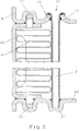
- Its tube sheet 8, as shown in FIG. 1, has parallel slots (12 in FIG. 5) into which one end of the flat tube 2 is inserted.
- the tube sheet consists of an aluminum sheet with a thickness of, for example, 1.2 mm. This sheet is cut at the locations of the slots. The edges of the cuts then become too Collar (14 in Fig. 5) bent.
- the ends of the double-flow flat tubes 2 are inserted into their respective slots 12 to such an extent that free ends 16 of the flat tubes protrude beyond the collars.
- the free ends 16 are sculpted.
- the tulips are placed on the two long sides of the respective slot around the respective collar so far that the respective collar is gripped by more than 90 ° so that an undercut effect is achieved and a defined, extended soldering gap is formed between the bent-back tulip and the collar becomes.
- the tube sheet 8 is box-shaped with a circumferential side wall 24 and has a circumferential outer flange 26 which has a circumferential outer collar 28.
- the flat cover 10 of the water tank 6 is inserted between the outer flange 26 and the outer collar 28 and is soldered to the aluminum braze in a manner not shown.
- the lid 10 carries a partition 30 which divides the water tank 6 into two sections. One communicates with the inlet 32 and the other with the outlet 34 of the water as an internal heat exchange fluid.
- the flat tubes 2 are in the middle provided with a partition 36, which is arranged in the same plane as the partition 30 in the water tank.
- the partition walls 36 divide the respective flat tube 2 into two parallel channels 38, in which the inner heat exchanger fluid flows in countercurrent in accordance with the direction of flow indicated by arrows at the connections 32 and 34.
- This connection in counterflow is a double-flow flat tube 2.
- the flow is diverted at the ends of the flat tubes 2 facing away from the water tank 6 in that the two channels and thus the adjacent floods communicate as little throttled as possible.
- the partition 36 is omitted in this connection area 40 over such a length that the cross section of one channel 38 is completely or almost unthrottled in that of the other Channel 38 is transferred.
- the length over which the partition 36 is omitted in the connection area 40 of the communication is half to three times the distance between the outer wall and the partition 36 of the respective flat tube 2. In practical embodiments, this distance is in particular 0.5 to 2 mm.
- the other ends of the flat tubes 2 facing away from the water box 6 openly engage in grooves 42 of an end plate 44 parallel to the tube plate 8, where they are also soldered in by means of aluminum hard solder.
- the end plate 44 therefore forms the flow closure of these ends of the flat tubes 2.
- the end plate 44 holds the flat tubes 2 in the same manner as the slots 12 make on the tube plate 8, in the prescribed, generally equidistant, division.
- the end plate 44 can also serve to mount the entire heat exchanger on a supporting part of the motor vehicle.
- a side plate 46 which in turn runs parallel to the flat tubes 2, adjoins the outer zigzag fins 4.
- Each of these two side plates 46 has pawls 48 and 50 which engage in the water tank 6 and in the end plate 44.
- the extensions 48 and 50 can be tab-like extensions as shown in FIG. 1 or alternatively as shown in FIG. 5, exhibitors made from side flanges of the side plates 46, these side flanges being oriented parallel to the tube plate 8 or the end plate 44 and the exhibitors in each case engage in corresponding recesses 52 (see FIG. 5) in the tube sheet 8 or the end plate 44.
- the holding recesses 52 in which the extensions 48 and 50 engage in a pawl-like manner in both embodiments, can be obtained by appropriate profiling of the sheet metal respectively forming the tube plate or the end plate without having to mill out own recesses .
- the side plates 46 are in their central area clamped by at least one cross strut 54 on both sides of the narrow end faces of the flat tubes 2 so that the cross struts 54 and the side plates 46 produce a mechanical ring closure around the flat tubes 2 and the zigzag fins 4.
- the connection is again made using aluminum hard solder.
- the cross struts 54 are used both for fixing before soldering and later as additional reinforcement against burst pressure.
- the housing for the flat tubes 2 and the zigzag fins 4 formed by the tube sheet 8, the end plate 44, the side plates 46 and the cross struts 54 also fixes the entire unit mechanically before the soldering and then simultaneously forms the housing of the heat exchanger.
- the entire housing is suitably made of aluminum or an aluminum alloy. All connection points, in particular those between the flat tubes 2 and the zigzag fins 4, the ends of the flat tubes 2 in the slots in the tube sheet 8, if appropriate its connection to the cover 10 of the water tank 6 and the connections of the other housing are expediently produced in a single soldering process, in which the pre-coated solder, in particular hard solder, is heated.
- An arrow 56 in FIG. 1 shows the direction of flow of the air, to which the water in the two channels 38 inside the flat tubes 2 is double-flow and thus in countercurrent flow.
- a pattern of punctiform wall indentations 60 is distributed over both flat sides of the flat tubes 2 in the area of both channels 38 according to a grid that is inclined to the axis of the respective flat tube 2 according to the angle a (see FIG. 2), and which acts as a spacer for the opposite flat sides of the Flat tubes 2 serve.
- This arrangement of the indentations 60 is provided in addition to the construction of the partition 36, regardless of its design in detail, as described in several alternatives, for example below.
- there may be indentations 60 which are one from both flat sides Go out flat tube 2, support each other at the end. Variants of mutual nesting and support of indentations on one flat side on a flat opposite side of the flat tube are possible. Under certain circumstances, one can provide all the indentations on one side of the flat tube or else, according to a predetermined pattern, provide the indentations on both flat tubes with a mutual offset.
- the two flat sides of a flat tube 2 are not only supported with respect to one another by the respective indentations, but are even soldered to one another with aluminum hard solder, as a result of which the bursting pressure of the tube can be increased significantly.
- the indentations 60 also have a function as turbulence-generating means for the water in the flat tube 2 and are no longer required where the flow no longer takes place, i.e. in the engagement area in the end plate 44.
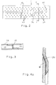
- the closed circumference of the flat tube is formed by an overlap in the area of the central partition 36. Due to this overlap of the sheet metal part, the external flux access occurs at the same time.
- the partition 36 is recessed so that both flow channels 38 can communicate.
- the communication connection between the two floods with the maximum opening cross section shown is still two wall thicknesses of the flat tube narrower than in subsequent channels 38.
- the sharp-edged wall ends in addition to the communication opening result in a relatively high drag coefficient.
- the sheet metal part, from which the flat tube 2 is bent is not only cut out in the region of the partition wall 36, but additionally cut out there on both sides along a section 90 which extends along the overlap of the sheet metal part.
- the two overlap points of the area of the sheet metal part which has not been cut out are thus offset from one another in the transverse direction of the flat tube and each form a throttle opening with constriction in each case only by one wall thickness.
- the resistance coefficient in the area 40 of the communication opening is additionally reduced by the fact that the boundary of the cutout no longer runs bluntly as in FIG. 3, but at an acute angle ⁇ of preferably 30 ° to 60 ° with respect to the planes of the flat sides of the flat tube 2 .
- the acute angle ⁇ is obtained on the sheet metal part in a prefabrication stage by obliquely punching out the cutout in accordance with the dashed lines in FIG. 4.
- the section 90 should make up at least one wall thickness. Practical is e.g. a dimension of three to five wall thicknesses.
Landscapes
- Engineering & Computer Science (AREA)
- Physics & Mathematics (AREA)
- Thermal Sciences (AREA)
- Mechanical Engineering (AREA)
- General Engineering & Computer Science (AREA)
- Heat-Exchange Devices With Radiators And Conduit Assemblies (AREA)
Claims (13)
- Echangeur de chaleur eau/air en aluminium ou en un alliage d'aluminium pour véhicules automobiles, notamment échangeur de chaleur de chauffage ou radiateur de moteur, comprenant un arrangement en rangée à au moins deux flux de tubes plats parallèles (2) qui sont assemblés les uns aux autres par soudage par l'intermédiaire de lamelles en zigzag (4) et au moins une boîte à eau (6) raccordée de façon communicante aux premières extrémités des tubes plats (2) et dans laquelle une cloison (30) sépare une chambre d'entrée munie d'une entrée (32) d'une chambre de sortie munie d'une sortie (34) et dont le fond tubulaire (8) présente des fentes (12) dans lesquelles les extrémités des tubes plats sont emmanchées et où elles sont soudées contre le fond tubulaire (8), cependant queles tubes plats (2) eux-mêmes sont aménagés à au moins deux flux par au moins une cloison (36) qui s'étend dans la direction longitudinale, la cloison (36) étant évidée entre les flux à contre-courant adjacents dans une région de raccordement (40) aux extrémités des tubes plats (2) éloignées de la boîte à eau (6), sur une longueur le long de laquelle les flux à contre-courant adjacents communiquent,la cloison (36) est formée par déformation d'une seule pièce de tôle qui forme le tube plat (2) et qui est découpée pour former la région de raccordement (40), etla communication se produit sans étranglement ou avec une réduction égale au maximum à deux épaisseurs de paroi du tube plat (2) dans la région de raccordement (40) qui établit la communication entre les flux à contre-courant adjacents,caractérisé,en ce que la cloison (36) n'est formée que d'une épaisseur de matière de la pièce de tôle, laquelle pièce est pliée dans la région de la cloison (36), pour passer d'un côté plat du tube plat (2) à l'autre côté plat de ce tube et, à chaque zone de jonction avec le côté plat du tube plat (2) qui la prolonge, cette cloison forme avec une extrémité de la pièce de tôle un joint à recouvrement qui est lisse extérieurement le long de la dimension transversale du côté plat en question, eten ce que, le long des flux à contre-courant, des dépressions (60) de la paroi sont réparties sur la paroi des tubes plats (2) à la façon d'une trame, d'un côté ou des deux côtés, lesquelles dépressions sont de dimensions propres à former des entretoises d'écartement pour les deux côtés plats du tube plat (2) en question, en supplément de la cloison (36) correspondante.
- Echangeur de chaleur selon la revendication 1, caractérisé en ce que les extrémités des tubes plats (2) qui sont éloignées de la caisse à eau (6) sont soudées dans des rainures (42) d'une plaque de fermeture (44).
- Echangeur de chaleur selon la revendication 1 ou 2, caractérisé en ce que le paquet composé de tubes plats (2) et de lamelles en zigzag (4) est tenu entre des plaques latérales (46) et soudé à ces dernières et en ce que, de leur côté, les plaques latérales (46) sont engagées avec liaison par sûreté de forme et fixation par soudage dans des évidements de retenue prévus aussi bien dans le fond tubulaire (8) de la boîte à eau (6) que dans la plaque de fermeture (44).
- Echangeur de chaleur selon une des revendications 1 à 3, caractérisé en ce que le couvercle (10) de la caisse à eau (6) correspondante est lui aussi composé d'aluminium ou d'un alliage d'aluminium et est soudé au fond tubulaire (8).
- Echangeur de chaleur selon une des revendications 1 à 3, caractérisé en ce que, dans le cas où les dépressions (60) sont disposées des deux côtés, ces dépressions s'appuient l'une contre l'autre, de préférence par leurs faces frontales ou par les flancs adjacents.
- Echangeur de chaleur selon une des revendications 1 à 5, caractérisé en ce que les dépressions (60) d'une paroi sont soudées à la paroi opposée, ou de nouveau à des dépressions de paroi, du même tube plat.
- Echangeur de chaleur selon une des revendications 1 à 6, caractérisé en ce que les dépressions de paroi sont réparties à la façon d'une trame de points.
- Echangeur de chaleur selon la revendication 7, caractérisé en ce que la trame est orientée pour former un angle différent de 90°, de préférence compris entre 3° et 20°, avec l'axe du tube plat (2) en question.
- Echangeur de chaleur eau/air selon une des revendications 1 à 8, caractériséen ce qu'il est prévu, pour le soudage de la cloison (36) du tube plat (2) en question, une entrée extérieure de fondant qui est fermée par la soudure après le soudage, eten ce que l'entrée extérieure de fondant est prévue dans la région d'un recouvrement de la pièce de tôle dans la région des jonctions lisses des deux côtés.
- Echangeur de chaleur selon une des revendications 1 à 9, caractérisé en ce que la pièce de tôle à partir de laquelle le tube plat (2) est formé est préalablement revêtue de soudure sur les deux faces.
- Echangeur de chaleur selon une des revendications 1 à 9, caractérisé en ce que, dans la région de raccordement (40) de la communication entre les flux à contre-courant, la pièce de tôle est découpée, non pas seulement dans le prolongement de la cloison (36) mais en supplément dans la zone qui y fait suite, de préférence qui y fait suite des deux côtés, le long d'une zone partielle de son recouvrement.
- Echangeur de chaleur selon la revendication 11, caractérisé en ce que la limite de la découpure s'étend obliquement par rapport aux plans des côtés plats du tube plat (2), de préférence sous un angle β de 30° à 60°.
- Echangeur de chaleur selon la revendication 11 ou 12, caractérisé en ce que, dans la région de recouvrement, des rainures de guidage (14) prévues pour le fondant sont formées dans la pièce de tôle, le long de la zone de recouvrement.
Applications Claiming Priority (4)
| Application Number | Priority Date | Filing Date | Title |
|---|---|---|---|
| DE9309822U DE9309822U1 (de) | 1993-07-01 | 1993-07-01 | Wasser/Luft-Wärmetauscher aus Aluminium für Kraftfahrzeuge |
| DE9309822U | 1993-07-01 | ||
| DE9318525U | 1993-12-03 | ||
| DE9318525U DE9318525U1 (de) | 1993-12-03 | 1993-12-03 | Wasser/Luft-Wärmetauscher aus Aluminium für Kraftfahrzeuge |
Publications (2)
| Publication Number | Publication Date |
|---|---|
| EP0632245A1 EP0632245A1 (fr) | 1995-01-04 |
| EP0632245B1 true EP0632245B1 (fr) | 1997-10-15 |
Family
ID=25960984
Family Applications (1)
| Application Number | Title | Priority Date | Filing Date |
|---|---|---|---|
| EP94110227A Expired - Lifetime EP0632245B1 (fr) | 1993-07-01 | 1994-06-30 | Echangeur de chaleur eau-air en aluminium pour véhicules automobiles |
Country Status (2)
| Country | Link |
|---|---|
| EP (1) | EP0632245B1 (fr) |
| DE (1) | DE59404311D1 (fr) |
Cited By (1)
| Publication number | Priority date | Publication date | Assignee | Title |
|---|---|---|---|---|
| CN101240981B (zh) * | 2007-02-05 | 2010-05-26 | 白星龙 | 废水热量回收机 |
Families Citing this family (37)
| Publication number | Priority date | Publication date | Assignee | Title |
|---|---|---|---|---|
| WO1996034245A1 (fr) * | 1995-04-26 | 1996-10-31 | Helmut Lingemann Gmbh & Co. | Tube plat a cavites multiples pour echangeurs de chaleur et son procede de fabrication |
| DE19515528C2 (de) * | 1995-04-27 | 1997-04-24 | Thermal Werke Beteiligungen Gm | Umlenkkammer aus Blech für zwei- oder mehrflutige Flachrohre von Wärmetauschern für Kraftfahrzeuge |
| FR2738905B1 (fr) * | 1995-09-20 | 1997-12-05 | Valeo Climatisation | Tube d'echangeur de chaleur a canaux de circulation a contre-courant |
| DE19548244B4 (de) * | 1995-12-22 | 2006-03-02 | Behr Gmbh & Co. Kg | Verfahren zur Herstellung von hartgelöteten Aluminium-Wärmetauschern |
| DE19548495C2 (de) * | 1995-12-22 | 2000-04-20 | Valeo Klimatech Gmbh & Co Kg | Wärmetauscherblock für Wärmetauscher für Kraftfahrzeuge und Verfahren zu dessen Herstellung |
| FR2751403B1 (fr) * | 1996-07-22 | 1998-10-09 | Valeo Thermique Moteur Sa | Tube plat a circulation a contre-courant pour echangeur de chaleur |
| JPH1047887A (ja) * | 1996-07-31 | 1998-02-20 | Sanden Corp | 熱交換器 |
| DE29614186U1 (de) * | 1996-08-20 | 1997-12-18 | AKG-Thermotechnik GmbH & Co. KG, 34369 Hofgeismar | Wärmetauscher, insbesondere Wäschetrocknerkondensator, und zu dessen Herstellung bestimmte Rohranordnung |
| FR2755221B1 (fr) * | 1996-10-30 | 1999-01-08 | Valeo Thermique Moteur Sa | Echangeur de chaleur comprenant des tubes a canal double, en particulier pour vehicule automobile |
| JPH10185463A (ja) * | 1996-12-19 | 1998-07-14 | Sanden Corp | 熱交換器 |
| SE511517C2 (sv) * | 1997-04-22 | 1999-10-11 | Volvo Lastvagnar Ab | Anordning vid en plattvärmeväxlare för montering vid ett stativ eller liknande |
| JPH11287587A (ja) | 1998-04-03 | 1999-10-19 | Denso Corp | 冷媒蒸発器 |
| JP4175443B2 (ja) * | 1999-05-31 | 2008-11-05 | 三菱重工業株式会社 | 熱交換器 |
| BR0100661A (pt) * | 2000-02-25 | 2001-10-09 | Denso Corp | Trocador de calor |
| FR2810727B1 (fr) * | 2000-06-21 | 2003-09-26 | Valeo Thermique Moteur Sa | Tube plie pour un echangeur de chaleur et echangeur de chaleur comportant de tels tubes |
| FR2811746B1 (fr) * | 2000-07-12 | 2002-11-01 | Valeo Thermique Moteur Sa | Tube pour echangeur de chaleur, en particulier de vehicule automobile, et echangeur de chaleur comportant de tels tubes |
| AU5591301A (en) * | 2000-08-08 | 2002-02-14 | Modine Manufacturing Company | Method of making a tube for a heat exchanger |
| DE10051070A1 (de) * | 2000-10-11 | 2002-04-25 | Behr Gmbh & Co | Verfahren zur Herstellung von Flachrohren für einen Wärmeübertrager |
| GB0101697D0 (en) * | 2001-01-23 | 2001-03-07 | Emerson & Renwick Ltd | Heat exchanger tube |
| DE10212249A1 (de) * | 2002-03-20 | 2003-10-02 | Behr Gmbh & Co | Wärmetauscher und Kühlsytem |
| DE102004041101A1 (de) * | 2004-08-24 | 2006-03-02 | Behr Gmbh & Co. Kg | Flachrohr für einen Wärmeübertrager, insbesondere für Kraftfahrzeuge und Verfahren zur Herstellung eines Flachrohres |
| DE102005048227A1 (de) * | 2005-10-07 | 2007-04-12 | Behr Gmbh & Co. Kg | Heizkörper, Kühlkreislauf, Klimagerät für eine Kraftfahrzeug-Klimaanlage sowie Klimaanlage für ein Kraftfahrzeug |
| DE102006019823B4 (de) * | 2006-04-28 | 2011-01-27 | Arup Alu-Rohr Und -Profil Gmbh | Verfahren und Vorrichtung zur Herstellung von Rohren |
| DE102008007601A1 (de) | 2008-02-04 | 2009-08-06 | Behr Gmbh & Co. Kg | Mehrkammer-Flachrohr, Wärmetauscher und Verwendung eines Wärmetauschers |
| DE102008007610A1 (de) | 2008-02-04 | 2009-08-06 | Behr Gmbh & Co. Kg | Mehrkammer-Flachrohr, Wärmetauscher und Verwendung eines Wärmetauschers |
| DE102008007597A1 (de) | 2008-02-04 | 2009-08-06 | Behr Gmbh & Co. Kg | Herstellungsverfahren Mehrkammer-Flachrohr, Wärmetauscher und Verwendung eines Wärmetauschers |
| DE102009021180A1 (de) | 2009-05-13 | 2010-11-18 | Behr Gmbh & Co. Kg | Wärmeübertrager |
| DE102009043689A1 (de) * | 2009-10-01 | 2011-04-07 | Behr Gmbh & Co. Kg | Wärmeübertrager |
| US8443873B2 (en) * | 2009-12-02 | 2013-05-21 | Keihin Corporation | Heat exchanger for vehicular air conditioning apparatus |
| DE102010031468A1 (de) * | 2010-07-16 | 2012-01-19 | Behr Gmbh & Co. Kg | Fluidkanal für einen Wärmetauscher |
| DE102011008118B4 (de) | 2011-01-07 | 2012-10-18 | Arup Alu-Rohr Und Profil Gmbh | Wärmetauscher sowie Mehrkammerflachrohr dafür |
| CN102141326B (zh) * | 2011-04-29 | 2013-07-03 | 上海交通大学 | 微通道平行流蒸发器 |
| FR2986313A1 (fr) | 2012-01-31 | 2013-08-02 | Valeo Systemes Thermiques | Tube d'echangeur thermique, echangeur thermique et procede d'obtention correspondant |
| CN103867284B (zh) * | 2012-12-10 | 2016-06-08 | 北汽福田汽车股份有限公司 | 发动机散热器、发动机总成和车辆 |
| SE539124C2 (sv) | 2014-04-22 | 2017-04-11 | Titanx Engine Cooling Holding Ab | Fordonsvärmeväxlarrör och fordonskylare innefattande sådant rör samt sätt att bilda ett fordonsvärmeväxlarrör |
| CN105057901A (zh) * | 2015-07-31 | 2015-11-18 | 浙江金宸三普换热器有限公司 | 微通道平行流换热器的加工方法 |
| CN116105513B (zh) * | 2023-02-03 | 2026-01-27 | 赛力斯汽车有限公司 | 一种应用于汽车散热器的冷却管及其制备方法 |
Family Cites Families (4)
| Publication number | Priority date | Publication date | Assignee | Title |
|---|---|---|---|---|
| DE3440489A1 (de) * | 1984-11-06 | 1986-05-07 | Süddeutsche Kühlerfabrik Julius Fr. Behr GmbH & Co KG, 7000 Stuttgart | Kuehler, insbesondere fuer die kuehlanlage eines verbrennungsmotors eines kraftfahrzeuges |
| DE8816980U1 (de) * | 1988-02-06 | 1991-08-22 | Happel GmbH & Co, 4690 Herne | Röhrenwärmetauscher |
| JP2703384B2 (ja) * | 1990-02-09 | 1998-01-26 | 株式会社ゼクセル | 熱交換器用チューブのuターン部の製造方法及びこのチューブを用いた熱交換器の製造方法 |
| US5186250A (en) * | 1990-05-11 | 1993-02-16 | Showa Aluminum Kabushiki Kaisha | Tube for heat exchangers and a method for manufacturing the tube |
-
1994
- 1994-06-30 EP EP94110227A patent/EP0632245B1/fr not_active Expired - Lifetime
- 1994-06-30 DE DE59404311T patent/DE59404311D1/de not_active Expired - Lifetime
Cited By (1)
| Publication number | Priority date | Publication date | Assignee | Title |
|---|---|---|---|---|
| CN101240981B (zh) * | 2007-02-05 | 2010-05-26 | 白星龙 | 废水热量回收机 |
Also Published As
| Publication number | Publication date |
|---|---|
| DE59404311D1 (de) | 1997-11-20 |
| EP0632245A1 (fr) | 1995-01-04 |
Similar Documents
| Publication | Publication Date | Title |
|---|---|---|
| EP0632245B1 (fr) | Echangeur de chaleur eau-air en aluminium pour véhicules automobiles | |
| EP0656517B1 (fr) | Echangeur de chaleur eau-air en aluminium pour véhicules automobiles | |
| EP1281923B1 (fr) | Tube plat pour échangeur de chaleur et procédé de fabrication | |
| DE3752324T2 (de) | Kondensator | |
| EP0519334B1 (fr) | Echangeur de chaleur à tubes plats, procédé pour sa fabrication, applications et tubes plats pour échangeur de chaleur | |
| DE69115986T2 (de) | Rohr für Wärmetauscher und Verfahren zur Herstellung des Rohrs | |
| DE69202964T2 (de) | Wärmetauscher. | |
| DE69708730T2 (de) | Wärmetauscher und Verfahren zu seiner Herstellung | |
| EP1273864B1 (fr) | Echangeur de chaleur | |
| DE102007018879A1 (de) | Wärmetauscher | |
| DE112005000230T5 (de) | Wärmetauscher-Sammelbehälter und Wärmetauscher beinhaltend das Gleiche | |
| DE10315371A1 (de) | Wärmeübertrager | |
| DE4446817A1 (de) | Verdampfer für Klimaanlagen in Kraftfahrzeugen mit Mehrkammerflachrohren | |
| EP0929784B1 (fr) | Echangeur de chaleur a tubes aplatis retenus sur des collets d'un fond a tubes pour vehicules a moteur | |
| EP1411310B1 (fr) | Echangeur de chaleur à structure en serpentin | |
| EP1139052B1 (fr) | Refroidisseur pour véhicules et procédé de fabrication | |
| DE19933913C2 (de) | Verdampfer einer Kraftfahrzeugklimaanlage | |
| DE10150213A1 (de) | Stranggepreßtes Profil, insbesondere für Wärmetauscher | |
| EP1640684A1 (fr) | echangeur de chaleur à tubes plats et ailettes ondulées | |
| DE9309822U1 (de) | Wasser/Luft-Wärmetauscher aus Aluminium für Kraftfahrzeuge | |
| EP1148312B1 (fr) | Radiateur de véhicules | |
| DE102004007510B4 (de) | Wärmeübertrager, insbesondere Ölkühler für Kraftfahrzeuge | |
| DE10115580A1 (de) | Wärmetauscher | |
| DE102006002932A1 (de) | Wärmetauscher und Herstellungsverfahren für Wärmetauscher | |
| DE19814028A1 (de) | Doppel-Wärmetauscher |
Legal Events
| Date | Code | Title | Description |
|---|---|---|---|
| PUAI | Public reference made under article 153(3) epc to a published international application that has entered the european phase |
Free format text: ORIGINAL CODE: 0009012 |
|
| AK | Designated contracting states |
Kind code of ref document: A1 Designated state(s): DE ES FR |
|
| 17P | Request for examination filed |
Effective date: 19950126 |
|
| 17Q | First examination report despatched |
Effective date: 19951201 |
|
| GRAG | Despatch of communication of intention to grant |
Free format text: ORIGINAL CODE: EPIDOS AGRA |
|
| GRAH | Despatch of communication of intention to grant a patent |
Free format text: ORIGINAL CODE: EPIDOS IGRA |
|
| GRAH | Despatch of communication of intention to grant a patent |
Free format text: ORIGINAL CODE: EPIDOS IGRA |
|
| GRAA | (expected) grant |
Free format text: ORIGINAL CODE: 0009210 |
|
| AK | Designated contracting states |
Kind code of ref document: B1 Designated state(s): DE ES FR |
|
| PG25 | Lapsed in a contracting state [announced via postgrant information from national office to epo] |
Ref country code: FR Free format text: LAPSE BECAUSE OF FAILURE TO SUBMIT A TRANSLATION OF THE DESCRIPTION OR TO PAY THE FEE WITHIN THE PRESCRIBED TIME-LIMIT Effective date: 19971015 Ref country code: ES Free format text: THE PATENT HAS BEEN ANNULLED BY A DECISION OF A NATIONAL AUTHORITY Effective date: 19971015 |
|
| REF | Corresponds to: |
Ref document number: 59404311 Country of ref document: DE Date of ref document: 19971120 |
|
| EN | Fr: translation not filed | ||
| PLBE | No opposition filed within time limit |
Free format text: ORIGINAL CODE: 0009261 |
|
| STAA | Information on the status of an ep patent application or granted ep patent |
Free format text: STATUS: NO OPPOSITION FILED WITHIN TIME LIMIT |
|
| 26N | No opposition filed | ||
| PGFP | Annual fee paid to national office [announced via postgrant information from national office to epo] |
Ref country code: DE Payment date: 20130611 Year of fee payment: 20 |
|
| REG | Reference to a national code |
Ref country code: DE Ref legal event code: R071 Ref document number: 59404311 Country of ref document: DE |
|
| PG25 | Lapsed in a contracting state [announced via postgrant information from national office to epo] |
Ref country code: DE Free format text: LAPSE BECAUSE OF EXPIRATION OF PROTECTION Effective date: 20140701 |