EP0632273A1 - Dreiachsenluftdatensystem für Luftfahrzeuge - Google Patents
Dreiachsenluftdatensystem für Luftfahrzeuge Download PDFInfo
- Publication number
- EP0632273A1 EP0632273A1 EP94304777A EP94304777A EP0632273A1 EP 0632273 A1 EP0632273 A1 EP 0632273A1 EP 94304777 A EP94304777 A EP 94304777A EP 94304777 A EP94304777 A EP 94304777A EP 0632273 A1 EP0632273 A1 EP 0632273A1
- Authority
- EP
- European Patent Office
- Prior art keywords
- sensor
- airflow
- air vehicle
- air
- axial component
- Prior art date
- Legal status (The legal status is an assumption and is not a legal conclusion. Google has not performed a legal analysis and makes no representation as to the accuracy of the status listed.)
- Granted
Links
- 238000012937 correction Methods 0.000 claims abstract description 9
- 230000006870 function Effects 0.000 claims description 33
- 230000003068 static effect Effects 0.000 claims description 21
- 230000000903 blocking effect Effects 0.000 claims 3
- 230000000694 effects Effects 0.000 claims 1
- 238000009795 derivation Methods 0.000 description 10
- 238000005259 measurement Methods 0.000 description 9
- 239000000523 sample Substances 0.000 description 8
- RZVHIXYEVGDQDX-UHFFFAOYSA-N 9,10-anthraquinone Chemical compound C1=CC=C2C(=O)C3=CC=CC=C3C(=O)C2=C1 RZVHIXYEVGDQDX-UHFFFAOYSA-N 0.000 description 5
- 238000010586 diagram Methods 0.000 description 4
- 239000012530 fluid Substances 0.000 description 4
- 230000001419 dependent effect Effects 0.000 description 3
- 238000007726 management method Methods 0.000 description 3
- 239000011159 matrix material Substances 0.000 description 2
- 230000007704 transition Effects 0.000 description 2
- 238000009530 blood pressure measurement Methods 0.000 description 1
- 238000004364 calculation method Methods 0.000 description 1
- 238000000034 method Methods 0.000 description 1
Images





Classifications
-
- G—PHYSICS
- G01—MEASURING; TESTING
- G01P—MEASURING LINEAR OR ANGULAR SPEED, ACCELERATION, DECELERATION, OR SHOCK; INDICATING PRESENCE, ABSENCE, OR DIRECTION, OF MOVEMENT
- G01P5/00—Measuring speed of fluids, e.g. of air stream; Measuring speed of bodies relative to fluids, e.g. of ship, of aircraft
- G01P5/14—Measuring speed of fluids, e.g. of air stream; Measuring speed of bodies relative to fluids, e.g. of ship, of aircraft by measuring differences of pressure in the fluid
- G01P5/16—Measuring speed of fluids, e.g. of air stream; Measuring speed of bodies relative to fluids, e.g. of ship, of aircraft by measuring differences of pressure in the fluid using Pitot tubes, e.g. Machmeter
Definitions
- the present invention relates generally to air data sensing systems, and, in particular, to air data sensing systems which sense air data parameters on highly maneuverable air vehicles.
- air data sensors which sense various air data parameters such as airflow velocity and direction, air vehicle angle-of-attack and angle-of-sideslip, and static pressure.
- orthogonal air speed sensors which are capable of measuring local flow velocities through 360° of flow direction, which occurs when the sensors are mounted on the nose of a helicopter, are described in U.S. Patents 3,646,811 and 4,522,070, which are assigned to the assignee of the present application and are herein incorporated by reference.
- High performance fighter aircraft operate through a range of attack and sideslip which can be measured by a more conventional L-shaped multiple output pitot-static-flow angle air data sensors.
- air data sensors are positioned on the surface of the fuselage of an air vehicle.
- the air data sensors measure local airflow conditions dependent on the mounting location and the shape of the air vehicle.
- Local flow parameters such as local flow velocity magnitude and direction typically vary significantly from the free stream flow conditions.
- an air data sensing system is desired that obtains complete air data parameters indicative of the free stream flow conditions.
- the present invention relates to an apparatus on board an air vehicle for sensing a free stream flow parameter when mounted adjacent the air vehicle.
- a first sensor senses a longitudinal axial component and a lateral axial component of a parameter of local airflow immediately adjacent the first sensor and provides output signals as a function of the local longitudinal and lateral components.
- the first sensor is mounted on the air vehicle such that a longitudinal axis of the first sensor lies in a first reference plane including a reference longitudinal axis.
- a second sensor also senses a longitudinal axial component of the airflow parameter and also a second axial component of the airflow parameter in direction perpendicular to the lateral axial component sensed by the first sensor.
- the sensors provide output signals as a function of the local longitudinal and axial components of the airflow parameter being measured.
- the second sensor is mounted on the air vehicle such that a longitudinal axis of the second sensor means lies in a second plane substantially perpendicular to the first plane and including the reference longitudinal axis of the first plane which is at aknown relation to a longitudinal reference axis of the air vehicle.
- a correction unit obtains a signal representing the free stream flow parameter as a function of the output signals from the first and second sensors.
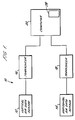
- a sensing system 10 illustrated schematically in Figure 1 senses free stream flow parameters utilizing airflow adjacent an air vehicle.
- System 10 is on board an air vehicle, and obtains complete three axis air data parameters from the airflow over the air vehicle.
- sensing system 10 is used to measure these air data parameters.
- sensing system 10 is used to measure the true static pressure (p) of the free stream airflow over the air vehicle.
- a first vertical air data sensor 12 senses local longitudinal (along the X axis) and lateral (along the Y axis) components of a parameter of local airflow immediately adjacent the vertical air data sensor.
- a second horizontal air data sensor 14 senses the local longitudinal (along the X axis) and vertical (along the Z axis) components of the parameter of local airflow immediately adjacent the horizontal data sensor.
- a transducer 16 receives the sensed local longitudinal and lateral parameter components sensed by sensor 12 and generates separate electrical signals, each as a function of one of the components.
- a transducer 18 receives the local longitudinal and vertical parameter components sensed by the sensor 14 and generates separate electrical signals each as a function of one of the components.
- a computer 20 receives the electrical signals from transducer 16 and transducer 18.
- Computer 20 is typically either the flight control or flight management computer on board the air vehicle.
- Computer 20 could, however, be implemented in a separate microprocessor or in a processor chip built into the transducers.
- Computer 20 calculates a signal representing the free stream flow parameter such as air speed having a longitudinal axial component, a lateral axial component, and a vertical axial component as a function of the signals from transducers 16 and 18.
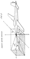
- the typical orientation of sensors 12 and 14 mounted on an air vehicle 22 is illustrated in Figure 3.
- the two sensors lie in intersecting planes that are perpendicular to each other and which include a common longitudinal axis at the intersection of the planes.
- the sensors are mounted close to the air vehicle fuselage nose indicated at 23.
- the vertical air data sensor 12 is typically mounted on a mounting surface 24 either on the top or the bottom of the fuselage and near the vertical center line of the air vehicle, indicated by the Z axis.
- the horizontal air data sensor 14 is mounted at a radial location approximately 90° from the vertical data sensor 12 either on the right or left side of the fuselage, on a mounting surface 26.
- the air vehicle 22 blocks airflow to the vertical sensor from the vertical direction behind mounting surface 24.
- the air vehicle blocks airflow to the horizontal sensor 14 from the lateral direction behind mounting surface 26.
- vertical sensor 12 is open to receive airflow from the longitudinal and lateral directions
- the horizontal sensor 14 is open to receive airflow from the longitudinal and vertical directions. Consequently, the vertical sensor 12 measures local longitudinal and lateral components of air speed represented as (V c ⁇ x ) and (V c ⁇ y ), respectively.
- the resultant local flow velocity (v c ⁇ l ) and local angle of sideslip flow direction ( ⁇ l ) are calculated as a function of the local longitudinal and lateral components of air speed.
- the horizontal sensor 14 measures local longitudinal and vertical components of air speed represented as (V c ⁇ x ) and (V c ⁇ c ), respectively.
- the resultant local flow velocity (V c ⁇ l ) and local angle of attack flow direction ( ⁇ l ) are calculated as a function of the local longitudinal and vertical components of air speed.
- the sensors 12 and 14 are implemented with a variety of air data sensors depending on the application. Sensors 12 and 14 sense various air data parameters such as airflow velocity and direction, air vehicle angle-of-attack and angle-of-sideslip, and static pressure. For instance in some applications an orthogonal air speed sensor is desired such as is described in the U.S. Patents 3,646,811 and 4,522,070, An orthogonal airspeed sensor measures local flow velocities through 360° of flow direction which occurs when the sensors are mounted on the nose of a helicopter. A more limited actual operating range of angle of attack and angle of sideslip permits sensors 12 and 14 to be more conventional L-shaped multiple output pitot-static-flow angle air data sensors such as the air data sensors described in U.S. Patents 3,318,146; 4,096,744; 4,378,696; and 4,836,019.
- air data sensors 12 and 14 are located on the aircraft fuselage surfaces 24 and 26, the sensors measure local flow conditions which are dependent on the mounting location and shape of air vehicle 22.
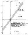
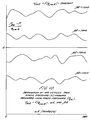
- the local flow velocity magnitude and direction measured typically vary significantly from the free stream flow conditions encountered by air vehicle 22. Therefore, the electrical signals from transducers 16 and 18 representing the measured outputs of sensors 12 and 14 are combined and corrected in computer 20 to obtain actual air vehicle flight parameters. The necessary corrections performed by computer 20 to obtain the true flight conditions from the local air data are illustrated graphically in Figures 4-11.
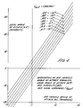
- Figure 4 illustrates that the air vehicle angle of attack ( ⁇ ) can be calculated from the functional relationship between the local angle of attack ( ⁇ l ) measured by the horizontal sensor 14 and the local angle of sideslip ( ⁇ l ) measured by the vertical sensor 12 when a constant resultant local flow velocity V c ⁇ l is assumed.
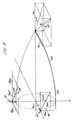
- the limited ranges of ⁇ l and ⁇ l represented in Figure 2 are representative of local flow limits of certain air vehicles such as conventional aircraft and helicopters operating at a high forward velocity. However, for certain applications such as helicopters flying at low velocities, ⁇ l and ⁇ l each range from 0° to 360°.
- the local air speed (V c ⁇ l ) measured by horizontal sensor 14 is typically not constant.
- ⁇ has a secondary dependency upon V c ⁇ l , which could be represented in a series of graphs to illustrate the complete flight range for possible values of V c ⁇ l .
- Computer 20 provides corrections for V c ⁇ l in a three-dimensional matrix or look-up table which defines aircraft angle of attack ( ⁇ ) in terms of all three independent variables ⁇ l , ⁇ l , and V c ⁇ l .
- the three-dimensional look-up table is stored in a large memory which is typically contained in the flight control or flight management computer indicated at 28 in Figure 1.
- the look up tables implement the information contained in the respective graphs shown in Figures 4-11.
- air vehicle angle of sideslip ( ⁇ ) is derived from the three independent variables ⁇ l measured by the horizontal sensor 14, ⁇ l measured by the vertical sensor 12, and V c ⁇ l measured by vertical sensor 12.
- Figure 5 illustrates only a limited range of ⁇ l and ⁇ l for a constant local air speed.
- computer corrections for V c ⁇ l are made in a known commonly use three-dimensional matrix or look-up table located in memory 28.
- the air vehicle vertical air speed component (V cz ) is derived from the three variables ⁇ l , ⁇ l , and V c ⁇ z as illustrated in Figure 8.
- the lateral air speed component (V cy ) is derived as a function of the three variables ⁇ l , ⁇ l , and V c ⁇ y as illustrated in Figure 9.
- the graphs of Figures 8 and 9 only illustrate limited ranges for ⁇ l and ⁇ l but could include ranges from 0° to 360°.
- each of the computer correction tables of memory 28 for V cx , V cy and V cz are implemented in three-dimensional look-up tables to account for varying ⁇ l and ⁇ l angles which are independent variables for each velocity component.
- the vertical sensor 12 also measures local static pressure (p l ⁇ ) and the horizontal sensor 14 measures local static pressure (P l ⁇ ).
- the local static pressure (p l ⁇ ) is utilized along with ⁇ l , ⁇ l , and V c ⁇ l to derive true static pressure (p) according to the functional relationships illustrated in Figure 10.
- the local static pressure (p l ⁇ ) along with ⁇ l , ⁇ l and V c ⁇ l are used to derive true static pressure (p) according to the functional relationships illustrated in Figure 11.
- two independent measurements of true static pressure (p) are obtainable. These two independent measurements are used for redundancy in separate user systems. Optionally, the two independent measurements are averaged for maximum accuracy.
- q cl is calculated from either V c ⁇ l which is derived from V cx and V cy for the vertical sensor 12 or from V c ⁇ l which is derived from V cx and V cz measured by horizontal sensor 14.
- the measured static pressure is easily obtained from the L-shaped multi-function air data sensor such as described in U.S. Patents 4,378,696 and 4,836,019. Whereas for lower velocity applications such as with helicopters, the orthogonal air speed sensor is used to measure static pressure using the relationships fully described in U.S. Patent 4,522,070.
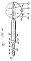
- a suitable orthogonal sensor which can be used for applications where ⁇ l and ⁇ l range from 0° to 360° is illustrated in Figures 12 and 13.
- a sensor 40 is comprised of housing 42 mounted in base 44. Housing 42 is an elongated tube closed at the end. As illustrated in Figure 13, the interior of housing 42 is divided by longitudinal walls 43 and 45 into two chamber pairs.
- the chambers are numbered 46, 48, 50 and 52.
- the bisecting plane of chambers 46 and 50 lies on the X axis.
- the chambers 46 and 50 comprise an oppositely facing chamber pair.
- the bisecting plane of chambers 48 and 52 lies on the Y axis. Chambers 48 and 52 comprise an oppositely facing chamber pair.
- Each chamber has pressure ports that pass through the wall of housing 42 and connect the respective chamber to the environment around sensor 40.
- Ports 54 open to chamber 46; ports 56 open to chamber 48; ports 58 open to chamber 50; and ports 60 open to chamber 52.
- Ports 54 face generally in opposite direction from ports 58 and ports 56 face generally in opposite direction from port 60.
- Tubes 46A, 48A, 50A, and 52A convey measured pressure signals from chambers 46, 48, 50 and 52, respectively.
- transducer 66 is an electrical signal that is a function of the pressure differential between chambers 48 and 52. Such electrical signal is fed to arithmetic unit 64. Arithmetic unit 64 performs the arithmetic functions necessary to generate an electrical signal that is a function of fluid velocity. Optionally, computer 20 (shown in Figure 1) can perform these arithmetic functions instead of arithmetic unit 64.
- Probe 80 measures a local flow angle or an angle of attack of the airflow over the surface of an air vehicle.
- a suitable multi-functional probe is disclosed in other patents assigned to the assignee of the present application such as the U.S. Patents 4,378,696 and 4,836,019.
- Probe 80 has a barrel 82 with three distinct sections.
- a first cylindrical section 84 includes a tapered forward end which has an opening or port 86 which is used for sensing the pitot pressure or total measured pressure (p m ).
- a plurality of static sensing ports 88 are arranged around the circumference of the section 84. The static pressure sensing ports 88 are separated with a forward bulkhead 90 and a rear bulkhead 92. The ports 88 are located in a region to provide measured static pressure (p m ).
- Probe 80 has a rear cylindrical section 94 which has a larger diameter than the diameter of forward cylindrical section 84.
- a transition section 96 having an expanding diameter in downstream direction joins the first section 84 and the rear section 94.
- a pair of angle of attack sensing ports 98 and 100 are provided through the wall of transition section 96.
- the ports 98 and 100 have axis lying in the plane in which the angle of attack is measured and face generally in opposite directions (down and up, respectively).
- a bulkhead 102 forms separate chambers for ports 98 and 100.
- the pressure of the first (lower) angle of attack sensing port 98 is represented as p ⁇ 1 and the pressure at the second (upper) angle of attack sensing port 100 is indicated by p ⁇ 2 .
- ⁇ 1 f [(P ⁇ 1 - p ⁇ 2 ) / q cN ], where q cN is a normalizing function measured by probe 80.
- q cN a normalizing function measured by probe 80.
- the normalizing function q cN 2 is preferable so that only two differential pressure measurements need to be made by the transducers 16 and 18 (shown in Figure 1) to generate the necessary signals to be able to derive the angle of attack. If q cN 2 is used, then the respective transducer provides the differential measurement of (p tm - p ⁇ 1 ) and (p ⁇ 1 - p ⁇ 2 ). Therefore, either a separate angle of attack computer or the computer 20 (shown in Figure 1) calculates the local angle of attack by the following equation:
- the device of the present invention obtains complete three axis actual flight air data parameters on highly maneuverable aircraft and helicopters. Moreover, for some measurements such as V cx and p redundant measurements are obtainable with the present invention. In the aircraft flight control industry and the weapon delivery industry, obtaining complete three axis air data which is not dependent upon the mounting location and shape of the air vehicle is important to provide accurate and reliable flight control and management.
Landscapes
- Engineering & Computer Science (AREA)
- Aviation & Aerospace Engineering (AREA)
- Physics & Mathematics (AREA)
- General Physics & Mathematics (AREA)
- Indicating Or Recording The Presence, Absence, Or Direction Of Movement (AREA)
- Feedback Control In General (AREA)
- Air Bags (AREA)
- Arrangements For Transmission Of Measured Signals (AREA)
Applications Claiming Priority (2)
| Application Number | Priority Date | Filing Date | Title |
|---|---|---|---|
| US08/085,294 US5369993A (en) | 1993-06-30 | 1993-06-30 | Three axis air data system for air vehicles |
| US85294 | 1993-06-30 |
Publications (2)
| Publication Number | Publication Date |
|---|---|
| EP0632273A1 true EP0632273A1 (de) | 1995-01-04 |
| EP0632273B1 EP0632273B1 (de) | 1998-11-04 |
Family
ID=22190663
Family Applications (1)
| Application Number | Title | Priority Date | Filing Date |
|---|---|---|---|
| EP94304777A Expired - Lifetime EP0632273B1 (de) | 1993-06-30 | 1994-06-30 | Dreiachsenluftdatensystem für Luftfahrzeuge |
Country Status (4)
| Country | Link |
|---|---|
| US (1) | US5369993A (de) |
| EP (1) | EP0632273B1 (de) |
| AT (1) | ATE173090T1 (de) |
| DE (1) | DE69414308T2 (de) |
Cited By (1)
| Publication number | Priority date | Publication date | Assignee | Title |
|---|---|---|---|---|
| US6644112B2 (en) | 2001-11-21 | 2003-11-11 | Eads Deutschland Gmbh | Air data measuring device and air data system for flight vehicles |
Families Citing this family (21)
| Publication number | Priority date | Publication date | Assignee | Title |
|---|---|---|---|---|
| US5653538A (en) * | 1995-06-07 | 1997-08-05 | Rosemount Aerospace Inc. | Total temperature probe |
| US5616861A (en) * | 1995-06-07 | 1997-04-01 | Rosemount Aerospace Inc. | Three pressure pseudo -Δ-P sensor for use with three pressure air data probe |
| US6070475A (en) * | 1997-10-15 | 2000-06-06 | Rosemont Aerospace Inc. | Air data probe with heater means within wall |
| US6430996B1 (en) | 1999-11-09 | 2002-08-13 | Mark Anderson | Probe and integrated ice detection and air data system |
| US6594559B2 (en) * | 2001-05-08 | 2003-07-15 | Rosemount Aerospace Inc. | Iterative method of aircraft sideslip compensation for multi-function probe air data systems |
| US6526821B1 (en) | 2001-07-18 | 2003-03-04 | The United States Of America As Represented By The Administrator Of The National Aeronautics And Space Administration | Airfoil shaped flow angle probe |
| US6668640B1 (en) | 2002-08-12 | 2003-12-30 | Rosemount Aerospace Inc. | Dual-channel electronic multi-function probes and methods for realizing dissimilar and independent air data outputs |
| US7379839B2 (en) * | 2002-12-23 | 2008-05-27 | Rosemount Aerospace, Inc. | Multi-function air data probes employing neural networks for determining local air data parameters |
| US7257470B2 (en) * | 2004-10-29 | 2007-08-14 | Rosemount Aerospace Inc. | Fault isolation method and apparatus in artificial intelligence based air data systems |
| US7213454B2 (en) * | 2005-04-06 | 2007-05-08 | Rosemount Aerospace Inc. | Method and apparatus for obtaining improved accuracy and range for air data parameters inferred from independent measurements of interdependent pressures |
| US7377159B2 (en) | 2005-08-16 | 2008-05-27 | Honeywell International Inc. | Methods and system for determining angles of attack and sideslip using flow sensors |
| US20070130096A1 (en) * | 2005-12-01 | 2007-06-07 | Rosemount Aerospace, Inc. | Fault detection in artificial intelligence based air data systems |
| FR2916276B1 (fr) * | 2007-05-14 | 2009-08-28 | Airbus France Sas | Dispositif et procede d'estimation d'un angle d'incidence d'un aeronef |
| ES2394558B1 (es) * | 2010-01-18 | 2013-12-12 | Eads Construcciones Aeronáuticas, S.A. | Dispositivo de soporte para sonda. |
| FR2960596B1 (fr) * | 2010-05-25 | 2014-05-02 | Turbomeca | Dispositif d'acquisition/distribution multipoints de fluide, en particulier sonde de prise de pression dans une entree d'air de turbomachine |
| US9103731B2 (en) | 2012-08-20 | 2015-08-11 | Unison Industries, Llc | High temperature resistive temperature detector for exhaust gas temperature measurement |
| US10281303B2 (en) | 2015-03-23 | 2019-05-07 | Rosemount Aerospace, Inc. | Air data probe with improved performance at angle of attack operation |
| US9758257B1 (en) * | 2016-04-07 | 2017-09-12 | Sunlight Photonics Inc. | Airflow sensing systems and apparatus |
| WO2017161304A1 (en) * | 2016-03-18 | 2017-09-21 | Sunlight Photonics Inc. | Systems, methods, and apparatus for airflow sensing and close formation flight |
| US10017271B2 (en) * | 2016-03-18 | 2018-07-10 | Sunlight Photonics Inc. | Methods of three dimensional (3D) airflow sensing and analysis |
| US10928413B2 (en) * | 2018-10-05 | 2021-02-23 | Rosemount Aerospace Inc. | Aircraft freestream data systems |
Citations (4)
| Publication number | Priority date | Publication date | Assignee | Title |
|---|---|---|---|---|
| GB560019A (en) * | 1940-09-13 | 1944-03-16 | Clarence Leonard Johnson | Indicating instruments for aircraft |
| US3646811A (en) * | 1969-09-22 | 1972-03-07 | Rosemount Eng Co Ltd | Pressure sensor for determining fluid velocities |
| WO1982002944A1 (en) * | 1981-02-23 | 1982-09-02 | Inc Rosemount | Pressure sensor for determining airspeed,altitude and angle of attack |
| WO1985001578A1 (en) * | 1983-09-30 | 1985-04-11 | Rosemount Inc. | Method and apparatus for correcting barometric pressure for wind velocity and direction |
Family Cites Families (11)
| Publication number | Priority date | Publication date | Assignee | Title |
|---|---|---|---|---|
| US2661624A (en) * | 1949-08-15 | 1953-12-08 | Bendix Aviat Corp | Air speed indicating device |
| US2923152A (en) * | 1955-09-12 | 1960-02-02 | Douglas Aircraft Co Inc | 5-prong aerodynamic pickup |
| US3244001A (en) * | 1960-10-05 | 1966-04-05 | Douglas Aircraft Co Inc | Aerodynamic variables sensing device |
| US3222926A (en) * | 1961-07-10 | 1965-12-14 | Boeing Co | Air mass relative motion meter |
| US4074570A (en) * | 1977-03-15 | 1978-02-21 | Calspan Corporation | Fluid speed measuring apparatus |
| US4088019A (en) * | 1977-06-09 | 1978-05-09 | Anthony Mascia | Leeway angle indicator |
| US4235104A (en) * | 1979-03-19 | 1980-11-25 | The Board Of Trustees Of Western Michigan University | Normalized coefficient of lift indicator |
| US4843880A (en) * | 1985-01-14 | 1989-07-04 | Roland Sommer | Method for measuring the direction and force of gaseous or liquid flows and probe for carrying out this method |
| US4718273A (en) * | 1985-12-31 | 1988-01-12 | The Garrett Corporation | Combination alpha, static and total pressure probe |
| US4836019A (en) * | 1987-08-27 | 1989-06-06 | Rosemount Inc. | Compact air data sensor |
| US5117687A (en) * | 1990-01-11 | 1992-06-02 | Gerardi Joseph J | Omnidirectional aerodynamic sensor |
-
1993
- 1993-06-30 US US08/085,294 patent/US5369993A/en not_active Expired - Lifetime
-
1994
- 1994-06-30 EP EP94304777A patent/EP0632273B1/de not_active Expired - Lifetime
- 1994-06-30 DE DE69414308T patent/DE69414308T2/de not_active Expired - Lifetime
- 1994-06-30 AT AT94304777T patent/ATE173090T1/de active
Patent Citations (6)
| Publication number | Priority date | Publication date | Assignee | Title |
|---|---|---|---|---|
| GB560019A (en) * | 1940-09-13 | 1944-03-16 | Clarence Leonard Johnson | Indicating instruments for aircraft |
| US3646811A (en) * | 1969-09-22 | 1972-03-07 | Rosemount Eng Co Ltd | Pressure sensor for determining fluid velocities |
| WO1982002944A1 (en) * | 1981-02-23 | 1982-09-02 | Inc Rosemount | Pressure sensor for determining airspeed,altitude and angle of attack |
| US4378696A (en) * | 1981-02-23 | 1983-04-05 | Rosemount Inc. | Pressure sensor for determining airspeed altitude and angle of attack |
| WO1985001578A1 (en) * | 1983-09-30 | 1985-04-11 | Rosemount Inc. | Method and apparatus for correcting barometric pressure for wind velocity and direction |
| US4522070A (en) * | 1983-09-30 | 1985-06-11 | Rosemount Inc. | Method and apparatus for correcting barometric pressure for wind velocity and direction |
Cited By (2)
| Publication number | Priority date | Publication date | Assignee | Title |
|---|---|---|---|---|
| US6644112B2 (en) | 2001-11-21 | 2003-11-11 | Eads Deutschland Gmbh | Air data measuring device and air data system for flight vehicles |
| DE10157074C2 (de) * | 2001-11-21 | 2003-11-13 | Eads Deutschland Gmbh | Luftdaten-Meßvorrichtung für Fluggeräte |
Also Published As
| Publication number | Publication date |
|---|---|
| US5369993A (en) | 1994-12-06 |
| EP0632273B1 (de) | 1998-11-04 |
| DE69414308T2 (de) | 1999-06-17 |
| DE69414308D1 (de) | 1998-12-10 |
| ATE173090T1 (de) | 1998-11-15 |
Similar Documents
| Publication | Publication Date | Title |
|---|---|---|
| EP0632273B1 (de) | Dreiachsenluftdatensystem für Luftfahrzeuge | |
| EP1256812B1 (de) | Schiebewinkelkorrektur für ein multifunktionelles Luftdatensytem mit drei Sonden | |
| US3646811A (en) | Pressure sensor for determining fluid velocities | |
| US4096744A (en) | Pressure sensor for determining airspeed, altitude and angle of attack | |
| US7490510B2 (en) | Multi-function air data sensor | |
| EP0229534A2 (de) | Kombinationsdrucksonde | |
| US5349347A (en) | Method and apparatus for correcting dynamically induced errors in static pressure, airspeed and airspeed rate | |
| US6452542B1 (en) | Integrated flight management system | |
| US4378696A (en) | Pressure sensor for determining airspeed altitude and angle of attack | |
| US3318146A (en) | Pressure sensing instrument for aircraft | |
| EP1155329B1 (de) | Verfahren zum messen der hohen anstellwinkel und mach-zahl einer messsonde | |
| EP0597899B1 (de) | Anstellwinkelsensor basierend auf dem umgekehrten verhältnis von druckunterschieden | |
| JP3486672B2 (ja) | 四角錐台型5孔ピトー管を用いた広速度域飛行速度ベクトル計測システムにおける演算処理方法及び方式 | |
| EP1256863B1 (de) | Verfahren zur Abtriftwinkelberechnung und Korrektur des statischen Druckes für Abtrifteinflüsse, das Inertialinformation verwendet | |
| US6419186B1 (en) | Standoff mounting for air data sensing probes on a helicopter | |
| US20060178790A1 (en) | High-altitude capable wide velocity range flight velocity vector measurement probe and measurement system | |
| EP1256811A2 (de) | Multifunktionelle Luftdatensonden mit neuronalem Netzwerk zur Schiebewinkelkompensation | |
| US6101429A (en) | Broad-range, multi-directional aircraft airspeed measuring system | |
| US4127249A (en) | Apparatus for computing the rate of change of energy of an aircraft | |
| US20230408543A1 (en) | Speed detection device comprising a kiel probe | |
| AU575862B2 (en) | Method and apparatus for correcting barometric pressure for wind velocity and direction | |
| US5648604A (en) | Method and system for determining anemobaroclinometric parameters on board an aircraft | |
| JPH10332728A (ja) | 四角錐台型5孔プローブを用いた広速度域飛行速度ベクトル計測システム | |
| US7377159B2 (en) | Methods and system for determining angles of attack and sideslip using flow sensors | |
| GB2274338A (en) | Combined airspeed and direction detector, measurer and indicator |
Legal Events
| Date | Code | Title | Description |
|---|---|---|---|
| PUAI | Public reference made under article 153(3) epc to a published international application that has entered the european phase |
Free format text: ORIGINAL CODE: 0009012 |
|
| AK | Designated contracting states |
Kind code of ref document: A1 Designated state(s): AT BE CH DE DK ES FR GB GR IE IT LI LU MC NL PT SE |
|
| 17P | Request for examination filed |
Effective date: 19950327 |
|
| 17Q | First examination report despatched |
Effective date: 19961002 |
|
| RAP1 | Party data changed (applicant data changed or rights of an application transferred) |
Owner name: THE B.F. GOODRICH COMPANY |
|
| GRAG | Despatch of communication of intention to grant |
Free format text: ORIGINAL CODE: EPIDOS AGRA |
|
| GRAG | Despatch of communication of intention to grant |
Free format text: ORIGINAL CODE: EPIDOS AGRA |
|
| GRAH | Despatch of communication of intention to grant a patent |
Free format text: ORIGINAL CODE: EPIDOS IGRA |
|
| GRAH | Despatch of communication of intention to grant a patent |
Free format text: ORIGINAL CODE: EPIDOS IGRA |
|
| GRAA | (expected) grant |
Free format text: ORIGINAL CODE: 0009210 |
|
| AK | Designated contracting states |
Kind code of ref document: B1 Designated state(s): AT BE CH DE DK ES FR GB GR IE IT LI LU MC NL PT SE |
|
| PG25 | Lapsed in a contracting state [announced via postgrant information from national office to epo] |
Ref country code: SE Free format text: THE PATENT HAS BEEN ANNULLED BY A DECISION OF A NATIONAL AUTHORITY Effective date: 19981104 Ref country code: NL Free format text: LAPSE BECAUSE OF FAILURE TO SUBMIT A TRANSLATION OF THE DESCRIPTION OR TO PAY THE FEE WITHIN THE PRESCRIBED TIME-LIMIT Effective date: 19981104 Ref country code: LI Free format text: LAPSE BECAUSE OF FAILURE TO SUBMIT A TRANSLATION OF THE DESCRIPTION OR TO PAY THE FEE WITHIN THE PRESCRIBED TIME-LIMIT Effective date: 19981104 Ref country code: IT Free format text: LAPSE BECAUSE OF FAILURE TO SUBMIT A TRANSLATION OF THE DESCRIPTION OR TO PAY THE FEE WITHIN THE PRE;WARNING: LAPSES OF ITALIAN PATENTS WITH EFFECTIVE DATE BEFORE 2007 MAY HAVE OCCURRED AT ANY TIME BEFORE 2007. THE CORRECT EFFECTIVE DATE MAY BE DIFFERENT FROM THE ONE RECORDED.SCRIBED TIME-LIMIT Effective date: 19981104 Ref country code: GR Free format text: LAPSE BECAUSE OF NON-PAYMENT OF DUE FEES Effective date: 19981104 Ref country code: ES Free format text: THE PATENT HAS BEEN ANNULLED BY A DECISION OF A NATIONAL AUTHORITY Effective date: 19981104 Ref country code: CH Free format text: LAPSE BECAUSE OF FAILURE TO SUBMIT A TRANSLATION OF THE DESCRIPTION OR TO PAY THE FEE WITHIN THE PRESCRIBED TIME-LIMIT Effective date: 19981104 Ref country code: BE Free format text: LAPSE BECAUSE OF FAILURE TO SUBMIT A TRANSLATION OF THE DESCRIPTION OR TO PAY THE FEE WITHIN THE PRESCRIBED TIME-LIMIT Effective date: 19981104 Ref country code: AT Free format text: LAPSE BECAUSE OF FAILURE TO SUBMIT A TRANSLATION OF THE DESCRIPTION OR TO PAY THE FEE WITHIN THE PRESCRIBED TIME-LIMIT Effective date: 19981104 |
|
| REF | Corresponds to: |
Ref document number: 173090 Country of ref document: AT Date of ref document: 19981115 Kind code of ref document: T |
|
| REG | Reference to a national code |
Ref country code: CH Ref legal event code: EP |
|
| REF | Corresponds to: |
Ref document number: 69414308 Country of ref document: DE Date of ref document: 19981210 |
|
| REG | Reference to a national code |
Ref country code: IE Ref legal event code: FG4D |
|
| PG25 | Lapsed in a contracting state [announced via postgrant information from national office to epo] |
Ref country code: PT Free format text: LAPSE BECAUSE OF FAILURE TO SUBMIT A TRANSLATION OF THE DESCRIPTION OR TO PAY THE FEE WITHIN THE PRESCRIBED TIME-LIMIT Effective date: 19990204 Ref country code: DK Free format text: LAPSE BECAUSE OF FAILURE TO SUBMIT A TRANSLATION OF THE DESCRIPTION OR TO PAY THE FEE WITHIN THE PRESCRIBED TIME-LIMIT Effective date: 19990204 |
|
| ET | Fr: translation filed | ||
| NLV1 | Nl: lapsed or annulled due to failure to fulfill the requirements of art. 29p and 29m of the patents act | ||
| REG | Reference to a national code |
Ref country code: CH Ref legal event code: PL |
|
| PG25 | Lapsed in a contracting state [announced via postgrant information from national office to epo] |
Ref country code: LU Free format text: LAPSE BECAUSE OF NON-PAYMENT OF DUE FEES Effective date: 19990630 Ref country code: IE Free format text: LAPSE BECAUSE OF NON-PAYMENT OF DUE FEES Effective date: 19990630 |
|
| PLBE | No opposition filed within time limit |
Free format text: ORIGINAL CODE: 0009261 |
|
| STAA | Information on the status of an ep patent application or granted ep patent |
Free format text: STATUS: NO OPPOSITION FILED WITHIN TIME LIMIT |
|
| 26N | No opposition filed | ||
| PG25 | Lapsed in a contracting state [announced via postgrant information from national office to epo] |
Ref country code: MC Free format text: LAPSE BECAUSE OF NON-PAYMENT OF DUE FEES Effective date: 19991231 |
|
| REG | Reference to a national code |
Ref country code: IE Ref legal event code: MM4A |
|
| REG | Reference to a national code |
Ref country code: GB Ref legal event code: IF02 |
|
| PGFP | Annual fee paid to national office [announced via postgrant information from national office to epo] |
Ref country code: DE Payment date: 20120627 Year of fee payment: 19 |
|
| PGFP | Annual fee paid to national office [announced via postgrant information from national office to epo] |
Ref country code: GB Payment date: 20120625 Year of fee payment: 19 Ref country code: FR Payment date: 20120705 Year of fee payment: 19 |
|
| GBPC | Gb: european patent ceased through non-payment of renewal fee |
Effective date: 20130630 |
|
| REG | Reference to a national code |
Ref country code: DE Ref legal event code: R119 Ref document number: 69414308 Country of ref document: DE Effective date: 20140101 |
|
| REG | Reference to a national code |
Ref country code: FR Ref legal event code: ST Effective date: 20140228 |
|
| PG25 | Lapsed in a contracting state [announced via postgrant information from national office to epo] |
Ref country code: DE Free format text: LAPSE BECAUSE OF NON-PAYMENT OF DUE FEES Effective date: 20140101 Ref country code: GB Free format text: LAPSE BECAUSE OF NON-PAYMENT OF DUE FEES Effective date: 20130630 |
|
| PG25 | Lapsed in a contracting state [announced via postgrant information from national office to epo] |
Ref country code: FR Free format text: LAPSE BECAUSE OF NON-PAYMENT OF DUE FEES Effective date: 20130701 |