EP0632347A1 - Dispositif de nettoyage d'une surface - Google Patents
Dispositif de nettoyage d'une surface Download PDFInfo
- Publication number
- EP0632347A1 EP0632347A1 EP94304710A EP94304710A EP0632347A1 EP 0632347 A1 EP0632347 A1 EP 0632347A1 EP 94304710 A EP94304710 A EP 94304710A EP 94304710 A EP94304710 A EP 94304710A EP 0632347 A1 EP0632347 A1 EP 0632347A1
- Authority
- EP
- European Patent Office
- Prior art keywords
- blade
- imaging surface
- toner
- residual particles
- housing
- Prior art date
- Legal status (The legal status is an assumption and is not a legal conclusion. Google has not performed a legal analysis and makes no representation as to the accuracy of the status listed.)
- Granted
Links
Images



Classifications
-
- G—PHYSICS
- G03—PHOTOGRAPHY; CINEMATOGRAPHY; ANALOGOUS TECHNIQUES USING WAVES OTHER THAN OPTICAL WAVES; ELECTROGRAPHY; HOLOGRAPHY
- G03G—ELECTROGRAPHY; ELECTROPHOTOGRAPHY; MAGNETOGRAPHY
- G03G21/00—Arrangements not provided for by groups G03G13/00 - G03G19/00, e.g. cleaning, elimination of residual charge
- G03G21/0005—Arrangements not provided for by groups G03G13/00 - G03G19/00, e.g. cleaning, elimination of residual charge for removing solid developer or debris from the electrographic recording medium
- G03G21/0011—Arrangements not provided for by groups G03G13/00 - G03G19/00, e.g. cleaning, elimination of residual charge for removing solid developer or debris from the electrographic recording medium using a blade; Details of cleaning blades, e.g. blade shape, layer forming
Definitions
- This invention relates generally to electrophotographic printing, and more particularly, concerns an apparatus for cleaning the imaging surface.
- CRUs Customer Replacement Units
- CRUs Customer Replacement Units
- broad band failures are the most common type of cleaning failure, and are predominantly caused by the effects of cleaner sump fill, especially when the cleaner cavity is located above the cleaner as in a 12 o'clock blade cleaner.
- Fine line failures are caused by either debris trapped under the blade, (i.e. paper fibers), or by nicks in the blade edge. However, fine line failures occur at a much lower rate than broad band failures, especially in a 12 o'clock blade cleaner.
- US-A-3,660,863 to Gerbasi discloses an elastomeric blade for removing dry particulate material from a surface to which the particulate material is electrostatically bonded.
- the elastomeric blade has an acute angle in pressure contact with the surface.
- One object of the present invention is to strive to provide an improved cleaning system to cause tighter packing of toner particles in the sump. Accordingly, the present invention provides a cleaning apparatus in accordance with any one of the appended claims.
- FIG. 1 is a schematic diagram of the cleaning system in a CRU.
- a photoreceptor belt 80 is rotated in the direction of arrow 12.
- the blade 10 supported by a blade holder 20, contacts the surface (i.e. imaging or photoconductive) of the photoreceptor belt 80.
- the blade 10 has a cleaning edge for removing residual particles from the photoreceptor belt 80.
- On the opposite side of the photoreceptor belt 80 from the cleaning blade 10 is a blade support platen 70 to support the flexible photoreceptor belt 80 under the load being applied to the blade 10 for pressure contact with the photoreceptor surface.
- a cleaner -housing 40 contains a cleaner cavity or sump 50 for collecting the toner and other residual particles removed from the photoreceptor by the blade 10.
- the blade 10 can be covered by a "mountainous" pile 60 of toner which is densely packed, and may have areas of fused toner caked upon it. The result of which is that the blade 10 feels the effect of the toner lying on it and it's tip geometry (i.e. the relationship of the cleaning edge and blade face to the photoreceptor) is altered in some way such that broad band cleaning failures occur.
- a broad band cleaning failure is where the cleaning system has failed, leaving a band of toner on the imaging surface that is transferred to the copying media creating copy quality defects.
- the 80° blade tip, of the present invention has component forces, F' N and F' C , shown in Figure 5, which assist in keeping the blade 10 in contact with the photoreceptor 80 and directing toner away from the blade/photoreceptor surface.
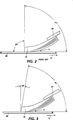
- FIG. 2 shows a common blade cleaner 15 that has about a 90° blade tip angle, ⁇ 2.
- a 90° blade has it's cleaning edge surface cut at 90° to the bulk of the blade.
- the blade cleaner is loaded to the photoreceptor 80 at approximately 55 gms per cm. This high blade loading was found to be necessary for operation at 12 o'clock without an active toner mover in the sump 50. The high blade load was necessitated by the 12 o'clock cleaner position due to higher forces being required to overcome the toner pile laying on the blade. Due to the high blade load in deflection, the working angle, ⁇ , of the blade 15 is 0° which is planing. (i.e.
- Planing refers to a blade operating at a working angle of 0°.
- the working angle being defined as the angle between the tip of the blade and it's adjacent blade surface, and the photoreceptor surface).
- the flat blade support platen 70 (see Figure 1) allows the blade to operate in the planing mode, which is unheard of for a drum photoreceptor in similar systems.
- the Xerox 1065 machine and the Xerox 5046 machine blade loads are in the 30 to 35 gm per cm range. Even a Xerox 5028 style cleaner, as in the present invention, will operate at 35 gms per cm, but not for very long.
- FIG 3 shows ⁇ 1, the blade cleaner 10, of the present invention, that has about an 80° blade tip angle.
- the blade 10 working angle, ⁇ is still 0°, but the tip angle is about 80° ⁇ 5° from the photoreceptor belt.
- the 80° blade tip angle modifies the forces on the blade/blade tip due to the effects of the toner pile that accumulates above the blade 10.
- Figure 4 shows the 90° blade and the rolling "log" of toner 60 in front of the blade tip. Also shown is a hypothetical vector force, F, (i.e. consisting of F N and F C ) resulting from the forces acting on the blade tip at the photoreceptor interface.
- F vector force
- Figure 5 shows an 80° blade tip angle, it's hypothesized vector force, F' (i.e. consisting of F' N and F' C ) and the rolling log of toner 60 as it starts to pile on top of the blade 10.
- F' hypothesized vector force
- the 80° blade allows the force, F', to be generated that helps to hold the blade tip down, or at least resist lifting off of the photoreceptor 80.
- FIG. 6 shows the experimental results of a reduced sump sized stress test (i.e. mini-sump test).
- a "roof” was placed over the blade approximately 10 mm above the photoreceptor surface. This was done to shorten the sump fill test time and create a real impedance to toner flow in the sump.
- the "standard” 90° blade was tested beyond it's predicted operating blade-to-photoreceptor interference range. [(i.e. Planing is predicted to occur at approximately 2.6 mm interference by a mathematical model. Testing was performed on the present invention, from the range of 2 mm to 4.5 mm interference with a blade holder angle of 26 ⁇ 1°. (Nominal interference is 3mm ⁇ 0.5mm.)]
- the 80° blade was initially tested at what would be a nominal setting. This graph shows that the 80° blade performed significantly better, at least 1.5 times better, than the 90° blade.
- the cleaning apparatus of the present invention includes a blade with an acute angle, having a high load and a baffle to guide particles removed from the surface into a sump thereby increasing the packing density of the sump fill.
- the present invention discloses a way to increase the toner storage capacity by simply changing the cut angle of the blade tip from 90° to 80 ⁇ 5°, adding a higher load on the blade cleaner and adding a baffle to guide residual particles.
- this idea does not increase the cost of the blade, it does not increase the size of the cleaner sump, and it does not introduce a mechanical device to pack the toner in the cleaner cavity. Therefore, the customer replacement unit life is improved through a reduced failure rate without an increase in the unit manufacturing cost (UMC).
- UMC unit manufacturing cost
Landscapes
- Physics & Mathematics (AREA)
- General Physics & Mathematics (AREA)
- Cleaning In Electrography (AREA)
Applications Claiming Priority (2)
| Application Number | Priority Date | Filing Date | Title |
|---|---|---|---|
| US08/083,603 US5319431A (en) | 1993-06-30 | 1993-06-30 | Apparatus for increased toner storage capacity |
| US83603 | 1993-06-30 |
Publications (2)
| Publication Number | Publication Date |
|---|---|
| EP0632347A1 true EP0632347A1 (fr) | 1995-01-04 |
| EP0632347B1 EP0632347B1 (fr) | 1998-06-03 |
Family
ID=22179448
Family Applications (1)
| Application Number | Title | Priority Date | Filing Date |
|---|---|---|---|
| EP94304710A Expired - Lifetime EP0632347B1 (fr) | 1993-06-30 | 1994-06-28 | Dispositif de nettoyage d'une surface |
Country Status (6)
| Country | Link |
|---|---|
| US (1) | US5319431A (fr) |
| EP (1) | EP0632347B1 (fr) |
| JP (1) | JP3524155B2 (fr) |
| BR (1) | BR9402591A (fr) |
| CA (1) | CA2126589C (fr) |
| DE (1) | DE69410701T2 (fr) |
Families Citing this family (6)
| Publication number | Priority date | Publication date | Assignee | Title |
|---|---|---|---|---|
| US5724640A (en) * | 1997-01-21 | 1998-03-03 | Xerox Corporation | Floating backer and mount for cleaning blades and spots blades on belt imaging surfaces |
| FR2858332B1 (fr) * | 2003-07-31 | 2005-10-28 | Cezus Co Europ Zirconium | Procede de fabrication d'un produit plat en alliage de zirconium, produit plat ainsi obtenu et element d'un assemblage combustible pour reacteur de centrale nucleaire realise a partir de ce produit plat |
| JP5403245B2 (ja) * | 2009-09-01 | 2014-01-29 | 株式会社リコー | クリーニングユニットおよび画像形成装置 |
| US8428481B2 (en) | 2010-07-21 | 2013-04-23 | Xerox Corporation | Long life cleaning system with reduced stress for start of cleaning blade operation |
| US8543048B2 (en) | 2010-07-21 | 2013-09-24 | Xerox Corporation | Electrophotographic marking system with blade cut angles for longer blade life |
| US8380116B2 (en) | 2010-07-21 | 2013-02-19 | Xerox Corporation | Cleaning edge modification for improved cleaning blade life and reliability |
Citations (3)
| Publication number | Priority date | Publication date | Assignee | Title |
|---|---|---|---|---|
| US4440488A (en) * | 1981-09-03 | 1984-04-03 | Mita Industrial Company Limited | Cleaning device for an image-carrying member |
| JPS60107686A (ja) * | 1983-11-17 | 1985-06-13 | Matsushita Electric Ind Co Ltd | 電子写真装置 |
| JPS60186887A (ja) * | 1984-03-06 | 1985-09-24 | Konishiroku Photo Ind Co Ltd | ブレ−ドクリ−ニング装置 |
Family Cites Families (15)
| Publication number | Priority date | Publication date | Assignee | Title |
|---|---|---|---|---|
| US3660863A (en) * | 1969-07-03 | 1972-05-09 | Xerox Corp | Cleaning apparatus |
| US3848993A (en) * | 1973-05-03 | 1974-11-19 | Xerox Corp | Supported developer blade cleaning |
| US4218131A (en) * | 1975-01-17 | 1980-08-19 | Canon Kabushiki Kaisha | Cleaning device |
| JPS5485037A (en) * | 1977-12-20 | 1979-07-06 | Konishiroku Photo Ind Co Ltd | Drum cleaning device of electrophotographic copier |
| US4255044A (en) * | 1979-07-09 | 1981-03-10 | Nashua Corporation | Cleaning blade for electrophotography |
| US4505577A (en) * | 1982-03-15 | 1985-03-19 | Ricoh Company, Ltd. | Toner powder collection device |
| JPH0743561B2 (ja) * | 1983-10-31 | 1995-05-15 | キヤノン株式会社 | クリーニング装置 |
| US4561766A (en) * | 1984-06-22 | 1985-12-31 | Xerox Corporation | Blade cleaner apparatus for removing toner from a charge-retentive surface |
| US4690544A (en) * | 1985-12-24 | 1987-09-01 | Xerox Corporation | Blade cleaning apparatus for flexible belt |
| US4875081A (en) * | 1988-10-24 | 1989-10-17 | Xerox Corporation | Electrophotographic device having a.c. biased cleaning member |
| JPH0345977A (ja) * | 1989-07-14 | 1991-02-27 | Canon Inc | 画像形成装置のクリーニング装置 |
| US4989047A (en) * | 1989-12-11 | 1991-01-29 | Xerox Corporation | Cleaning apparatus for the reduction of agglomeration-caused spotting |
| US5122839A (en) * | 1991-04-22 | 1992-06-16 | Xerox Corporation | Dual action blade cleaner |
| JPH04350890A (ja) * | 1991-05-29 | 1992-12-04 | Canon Inc | 画像形成装置のクリーニング装置 |
| US5229826A (en) * | 1991-11-04 | 1993-07-20 | Eastman Kodak Company | Toner cleaning apparatus |
-
1993
- 1993-06-30 US US08/083,603 patent/US5319431A/en not_active Expired - Fee Related
-
1994
- 1994-06-20 JP JP13679894A patent/JP3524155B2/ja not_active Expired - Fee Related
- 1994-06-23 CA CA002126589A patent/CA2126589C/fr not_active Expired - Fee Related
- 1994-06-28 DE DE69410701T patent/DE69410701T2/de not_active Expired - Fee Related
- 1994-06-28 EP EP94304710A patent/EP0632347B1/fr not_active Expired - Lifetime
- 1994-06-29 BR BR9402591A patent/BR9402591A/pt not_active IP Right Cessation
Patent Citations (3)
| Publication number | Priority date | Publication date | Assignee | Title |
|---|---|---|---|---|
| US4440488A (en) * | 1981-09-03 | 1984-04-03 | Mita Industrial Company Limited | Cleaning device for an image-carrying member |
| JPS60107686A (ja) * | 1983-11-17 | 1985-06-13 | Matsushita Electric Ind Co Ltd | 電子写真装置 |
| JPS60186887A (ja) * | 1984-03-06 | 1985-09-24 | Konishiroku Photo Ind Co Ltd | ブレ−ドクリ−ニング装置 |
Non-Patent Citations (3)
| Title |
|---|
| ANONYMOUS: "MULTI-BLADE CLEANING SYSTEM FOR PHOTOCONDUCTOR CLEANING", RESEARCH DISCLOSURE, no. 266, June 1986 (1986-06-01), EMSWORTH, HAMPSHIRE, UK, pages 363 * |
| PATENT ABSTRACTS OF JAPAN vol. 10, no. 41 (P - 429)<2098> 18 February 1986 (1986-02-18) * |
| PATENT ABSTRACTS OF JAPAN vol. 9, no. 259 (P - 397)<1982> 17 October 1985 (1985-10-17) * |
Also Published As
| Publication number | Publication date |
|---|---|
| DE69410701D1 (de) | 1998-07-09 |
| EP0632347B1 (fr) | 1998-06-03 |
| JP3524155B2 (ja) | 2004-05-10 |
| CA2126589A1 (fr) | 1994-12-31 |
| CA2126589C (fr) | 1997-12-16 |
| BR9402591A (pt) | 1995-05-23 |
| JPH0736344A (ja) | 1995-02-07 |
| DE69410701T2 (de) | 1998-12-24 |
| US5319431A (en) | 1994-06-07 |
Similar Documents
| Publication | Publication Date | Title |
|---|---|---|
| US4865306A (en) | Friction pad fixture | |
| CA1083656A (fr) | Nettoyeur de lame vibrant | |
| EP0632347B1 (fr) | Dispositif de nettoyage d'une surface | |
| JPS60249169A (ja) | コロナ放電器のクリ−ニング装置 | |
| US5122839A (en) | Dual action blade cleaner | |
| EP1072960B1 (fr) | Unité de traitement d'un appareil de formation d'images qui comporte un chargeur rotatif et un dispositif de nettoyage mobile par un moteur pour contacter le chargeur | |
| US5543906A (en) | Cleaning apparatus disposed on an image forming apparatus | |
| US5038181A (en) | Image forming unit having means for preventing a cleansing blade from contacting an image holding member until image forming unit is used | |
| US5341199A (en) | Active sump fill device blade cleaning apparatus | |
| US5229826A (en) | Toner cleaning apparatus | |
| JP2005234468A (ja) | クリーニングユニット | |
| JP3355922B2 (ja) | 画像形成装置 | |
| JPH07179239A (ja) | ベルト状電子写真感光体 | |
| CN201820082U (zh) | 显影器件和使用显影器件的图像形成装置 | |
| US5323218A (en) | Passive sump fill baffle for blade cleaning apparatus | |
| EP0740225A2 (fr) | Nettoyage assisté par ultrasons pour réduire le frottement entre l'élément de nettoyage et le photorécepteur à l'aide d'une force de vibration normale | |
| US5386282A (en) | Blade controller assembly with modified cam | |
| US5268715A (en) | Photoconductive drum exposure prevention structure in a clamshell-type image forming apparatus | |
| JPS616679A (ja) | 廃トナ−回収装置 | |
| JPH0432698Y2 (fr) | ||
| JP2658875B2 (ja) | Epカートリッジ | |
| JPS58159572A (ja) | 電子写真装置のクリ−ニング装置 | |
| JPH0131192B2 (fr) | ||
| JPH04482A (ja) | 画像形成装置のクリーニング装置 | |
| JPH03160487A (ja) | クリーニング装置 |
Legal Events
| Date | Code | Title | Description |
|---|---|---|---|
| PUAI | Public reference made under article 153(3) epc to a published international application that has entered the european phase |
Free format text: ORIGINAL CODE: 0009012 |
|
| AK | Designated contracting states |
Kind code of ref document: A1 Designated state(s): DE FR GB |
|
| 17P | Request for examination filed |
Effective date: 19950704 |
|
| 17Q | First examination report despatched |
Effective date: 19961120 |
|
| GRAG | Despatch of communication of intention to grant |
Free format text: ORIGINAL CODE: EPIDOS AGRA |
|
| GRAG | Despatch of communication of intention to grant |
Free format text: ORIGINAL CODE: EPIDOS AGRA |
|
| GRAH | Despatch of communication of intention to grant a patent |
Free format text: ORIGINAL CODE: EPIDOS IGRA |
|
| GRAH | Despatch of communication of intention to grant a patent |
Free format text: ORIGINAL CODE: EPIDOS IGRA |
|
| GRAA | (expected) grant |
Free format text: ORIGINAL CODE: 0009210 |
|
| AK | Designated contracting states |
Kind code of ref document: B1 Designated state(s): DE FR GB |
|
| REF | Corresponds to: |
Ref document number: 69410701 Country of ref document: DE Date of ref document: 19980709 |
|
| ET | Fr: translation filed | ||
| PLBE | No opposition filed within time limit |
Free format text: ORIGINAL CODE: 0009261 |
|
| STAA | Information on the status of an ep patent application or granted ep patent |
Free format text: STATUS: NO OPPOSITION FILED WITHIN TIME LIMIT |
|
| 26N | No opposition filed | ||
| REG | Reference to a national code |
Ref country code: GB Ref legal event code: IF02 |
|
| PGFP | Annual fee paid to national office [announced via postgrant information from national office to epo] |
Ref country code: GB Payment date: 20040623 Year of fee payment: 11 |
|
| PGFP | Annual fee paid to national office [announced via postgrant information from national office to epo] |
Ref country code: DE Payment date: 20040708 Year of fee payment: 11 |
|
| REG | Reference to a national code |
Ref country code: GB Ref legal event code: 746 Effective date: 20050404 |
|
| PGFP | Annual fee paid to national office [announced via postgrant information from national office to epo] |
Ref country code: FR Payment date: 20050608 Year of fee payment: 12 |
|
| PG25 | Lapsed in a contracting state [announced via postgrant information from national office to epo] |
Ref country code: GB Free format text: LAPSE BECAUSE OF NON-PAYMENT OF DUE FEES Effective date: 20050628 |
|
| PG25 | Lapsed in a contracting state [announced via postgrant information from national office to epo] |
Ref country code: DE Free format text: LAPSE BECAUSE OF NON-PAYMENT OF DUE FEES Effective date: 20060103 |
|
| GBPC | Gb: european patent ceased through non-payment of renewal fee |
Effective date: 20050628 |
|
| REG | Reference to a national code |
Ref country code: FR Ref legal event code: ST Effective date: 20070228 |
|
| PG25 | Lapsed in a contracting state [announced via postgrant information from national office to epo] |
Ref country code: FR Free format text: LAPSE BECAUSE OF NON-PAYMENT OF DUE FEES Effective date: 20060630 |