EP0632355B1 - Verfahren und Vorrichtung zur Durchflusssteuerung einer Hydraulikpumpe - Google Patents
Verfahren und Vorrichtung zur Durchflusssteuerung einer Hydraulikpumpe Download PDFInfo
- Publication number
- EP0632355B1 EP0632355B1 EP94106424A EP94106424A EP0632355B1 EP 0632355 B1 EP0632355 B1 EP 0632355B1 EP 94106424 A EP94106424 A EP 94106424A EP 94106424 A EP94106424 A EP 94106424A EP 0632355 B1 EP0632355 B1 EP 0632355B1
- Authority
- EP
- European Patent Office
- Prior art keywords
- pump
- flow
- hydraulic
- amounts
- pumps
- Prior art date
- Legal status (The legal status is an assumption and is not a legal conclusion. Google has not performed a legal analysis and makes no representation as to the accuracy of the status listed.)
- Expired - Lifetime
Links
- 238000000034 method Methods 0.000 title claims description 12
- 238000006073 displacement reaction Methods 0.000 claims description 19
- 238000011022 operating instruction Methods 0.000 claims description 2
- 238000010586 diagram Methods 0.000 description 5
- 238000010276 construction Methods 0.000 description 3
- 238000005516 engineering process Methods 0.000 description 3
- 230000006870 function Effects 0.000 description 2
- 238000006243 chemical reaction Methods 0.000 description 1
- 238000007599 discharging Methods 0.000 description 1
Images


Classifications
-
- F—MECHANICAL ENGINEERING; LIGHTING; HEATING; WEAPONS; BLASTING
- F15—FLUID-PRESSURE ACTUATORS; HYDRAULICS OR PNEUMATICS IN GENERAL
- F15B—SYSTEMS ACTING BY MEANS OF FLUIDS IN GENERAL; FLUID-PRESSURE ACTUATORS, e.g. SERVOMOTORS; DETAILS OF FLUID-PRESSURE SYSTEMS, NOT OTHERWISE PROVIDED FOR
- F15B7/00—Systems in which the movement produced is definitely related to the output of a volumetric pump; Telemotors
-
- G—PHYSICS
- G05—CONTROLLING; REGULATING
- G05D—SYSTEMS FOR CONTROLLING OR REGULATING NON-ELECTRIC VARIABLES
- G05D7/00—Control of flow
- G05D7/06—Control of flow characterised by the use of electric means
- G05D7/0617—Control of flow characterised by the use of electric means specially adapted for fluid materials
- G05D7/0629—Control of flow characterised by the use of electric means specially adapted for fluid materials characterised by the type of regulator means
- G05D7/0676—Control of flow characterised by the use of electric means specially adapted for fluid materials characterised by the type of regulator means by action on flow sources
- G05D7/0682—Control of flow characterised by the use of electric means specially adapted for fluid materials characterised by the type of regulator means by action on flow sources using a plurality of flow sources
-
- F—MECHANICAL ENGINEERING; LIGHTING; HEATING; WEAPONS; BLASTING
- F04—POSITIVE - DISPLACEMENT MACHINES FOR LIQUIDS; PUMPS FOR LIQUIDS OR ELASTIC FLUIDS
- F04B—POSITIVE-DISPLACEMENT MACHINES FOR LIQUIDS; PUMPS
- F04B49/00—Control, e.g. of pump delivery, or pump pressure of, or safety measures for, machines, pumps, or pumping installations, not otherwise provided for, or of interest apart from, groups F04B1/00 - F04B47/00
- F04B49/06—Control using electricity
- F04B49/065—Control using electricity and making use of computers
-
- F—MECHANICAL ENGINEERING; LIGHTING; HEATING; WEAPONS; BLASTING
- F04—POSITIVE - DISPLACEMENT MACHINES FOR LIQUIDS; PUMPS FOR LIQUIDS OR ELASTIC FLUIDS
- F04B—POSITIVE-DISPLACEMENT MACHINES FOR LIQUIDS; PUMPS
- F04B2201/00—Pump parameters
- F04B2201/12—Parameters of driving or driven means
- F04B2201/1205—Position of a non-rotating inclined plate
- F04B2201/12051—Angular position
-
- F—MECHANICAL ENGINEERING; LIGHTING; HEATING; WEAPONS; BLASTING
- F04—POSITIVE - DISPLACEMENT MACHINES FOR LIQUIDS; PUMPS FOR LIQUIDS OR ELASTIC FLUIDS
- F04B—POSITIVE-DISPLACEMENT MACHINES FOR LIQUIDS; PUMPS
- F04B2203/00—Motor parameters
- F04B2203/06—Motor parameters of internal combustion engines
- F04B2203/0605—Rotational speed
-
- F—MECHANICAL ENGINEERING; LIGHTING; HEATING; WEAPONS; BLASTING
- F04—POSITIVE - DISPLACEMENT MACHINES FOR LIQUIDS; PUMPS FOR LIQUIDS OR ELASTIC FLUIDS
- F04B—POSITIVE-DISPLACEMENT MACHINES FOR LIQUIDS; PUMPS
- F04B2205/00—Fluid parameters
- F04B2205/05—Pressure after the pump outlet
-
- F—MECHANICAL ENGINEERING; LIGHTING; HEATING; WEAPONS; BLASTING
- F04—POSITIVE - DISPLACEMENT MACHINES FOR LIQUIDS; PUMPS FOR LIQUIDS OR ELASTIC FLUIDS
- F04B—POSITIVE-DISPLACEMENT MACHINES FOR LIQUIDS; PUMPS
- F04B2207/00—External parameters
-
- F—MECHANICAL ENGINEERING; LIGHTING; HEATING; WEAPONS; BLASTING
- F15—FLUID-PRESSURE ACTUATORS; HYDRAULICS OR PNEUMATICS IN GENERAL
- F15B—SYSTEMS ACTING BY MEANS OF FLUIDS IN GENERAL; FLUID-PRESSURE ACTUATORS, e.g. SERVOMOTORS; DETAILS OF FLUID-PRESSURE SYSTEMS, NOT OTHERWISE PROVIDED FOR
- F15B2211/00—Circuits for servomotor systems
- F15B2211/20—Fluid pressure source, e.g. accumulator or variable axial piston pump
- F15B2211/205—Systems with pumps
- F15B2211/2053—Type of pump
- F15B2211/20546—Type of pump variable capacity
-
- F—MECHANICAL ENGINEERING; LIGHTING; HEATING; WEAPONS; BLASTING
- F15—FLUID-PRESSURE ACTUATORS; HYDRAULICS OR PNEUMATICS IN GENERAL
- F15B—SYSTEMS ACTING BY MEANS OF FLUIDS IN GENERAL; FLUID-PRESSURE ACTUATORS, e.g. SERVOMOTORS; DETAILS OF FLUID-PRESSURE SYSTEMS, NOT OTHERWISE PROVIDED FOR
- F15B2211/00—Circuits for servomotor systems
- F15B2211/20—Fluid pressure source, e.g. accumulator or variable axial piston pump
- F15B2211/26—Power control functions
-
- F—MECHANICAL ENGINEERING; LIGHTING; HEATING; WEAPONS; BLASTING
- F15—FLUID-PRESSURE ACTUATORS; HYDRAULICS OR PNEUMATICS IN GENERAL
- F15B—SYSTEMS ACTING BY MEANS OF FLUIDS IN GENERAL; FLUID-PRESSURE ACTUATORS, e.g. SERVOMOTORS; DETAILS OF FLUID-PRESSURE SYSTEMS, NOT OTHERWISE PROVIDED FOR
- F15B2211/00—Circuits for servomotor systems
- F15B2211/20—Fluid pressure source, e.g. accumulator or variable axial piston pump
- F15B2211/265—Control of multiple pressure sources
-
- F—MECHANICAL ENGINEERING; LIGHTING; HEATING; WEAPONS; BLASTING
- F15—FLUID-PRESSURE ACTUATORS; HYDRAULICS OR PNEUMATICS IN GENERAL
- F15B—SYSTEMS ACTING BY MEANS OF FLUIDS IN GENERAL; FLUID-PRESSURE ACTUATORS, e.g. SERVOMOTORS; DETAILS OF FLUID-PRESSURE SYSTEMS, NOT OTHERWISE PROVIDED FOR
- F15B2211/00—Circuits for servomotor systems
- F15B2211/60—Circuit components or control therefor
- F15B2211/63—Electronic controllers
- F15B2211/6303—Electronic controllers using input signals
- F15B2211/633—Electronic controllers using input signals representing a state of the prime mover, e.g. torque or rotational speed
Definitions
- the present invention relates to a discharge flow control system and method of a hydraulic pump in hydraulic equipment such as excavator, loader, dozer, crane, etc., and more particularly to a discharge flow control system and method to make the hydraulic pump to discharge a fairly precise amount of flow required for a desired work
- the fundamental technologies required in the automation of construction equipment such as excavator include a position control technology for various moving parts, and an energy minimization technology for preventing flow loss.
- the most general way which has been used for the enhancement of the operation efficiency of equipment and for the precise position control is to compare the flow amount required by an operator with the tilt angle data of the swash plate in hydraulic pump by a tilt angle detecting means, and compensate for errors therebetween.
- Figure 1 shows a schematic diagram of hydraulic system in a conventional excavator.
- the hydraulic system has an engine 1 which serves as a power source, two variable displacement pumps 2 and 3 and an auxilliary pump 4 for discharging a constant amount of operating oil, two pump requlators 5 and 6 for controlling each pump by moving each swash plate in pumps 2 and 3, solenoid controlled proportional valves 7 and 8 for pumps 2.
- the conventional system described in the above has the drawbacks that a frequent operation error occurs due to hysterisis characteristics of the solenoid controlled proportional valves, and that a precise control of the discharge flow amount is difficult due to the variable efficiency of the pumps.
- the document FR-A-2 677 407 discloses a system for controlling a discharge flow amount of a hydraulic pump without the characterizing means of the claims 1 and 3 of the present invention.
- the European patent application EP-A-0 440 802 discloses a device for controlling hydraulic pumps in a hydraulic driving ciruit which is provided with at least one hydraulic pump having means for varying displacement, at least one hydraulic actuator and a flow rate control valve. Thereby, the pump delivery rate is controlled by holding the delivery pressure of the hydraulic pumpe higher a fixed value than the load pressure of a hydraulic actuator.
- a system for controlling a discharge flow amount of a hydraulic pump in a hydraulic system having an engine to drive the pump and at least on hydraulic actuator operated by oil flow from the pump comprising means for detecting the operating displacement of the hydraulic actuators; operating means for outputting the operating instructions of an operator as electric signal; the system comprises further: means for detecting the number of rotations of the engine, and generating a number of pulses equal to the number of rotations; means for detecting the tilt angle of a swash plate of the pump; means for detecting the load pressure acting on the pumps, and electronic control unit including means for calculating the required flow amounts of pumps needed to perform a predetermined operation from the required flow amounts of the hydraulic actuator, means for determining actual discharge flow amounts of the pumps acting on the hydraulic actuators, means for determining actual operating flow amounts of pumps, means for calculating pump flow differences between the required flow amounts and the actual discharge flow amounts and actuator flow differences between the required flow amounts and the actual operating flow amounts of the hydraulic actuator, means for calculating the target flow
- a method for calculating a discharge flow amount of a hydraulic pump in a hydraulic system having an engine to drive the pump and at least one hydraulic actuator operated by oil flow from the pump characterized by steps of detecting an operating displacement of the at least one actuator, a number of rotations of the engine, a tilt angle of a swash plate of the pump and a load pressure acting on the pump; calculating a required flow amount of the at least one hydraulic actuator needed to perform a predetermined operation; calculating a dischargeable flow amount of the pump from the load pressure acting thereto; calculating a required discharge flow amount of the pump needed to perform the predetermined operation; reading the number of rotations of the engine, the tilt angle of a swash plate of the pump, and the operating displacement of the at least one hydraulic actuator; calculating an actual discharge flow amount of the pump from the number of rotation, the tilt angle; calculating an actual operating flow amount of the pump acting on the at least one hydraulic actuator from the operating displacement of the at least one hydraulic actuator; calculating a
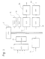
- Fig. 2 shows a schematic diagram of a hydraulic system in an excavator according to the present invention.
- a discharge flow control system in the excavator includes a rotation detector 14 detecting the rotation number of an engine 1, tilt angle detector 15 and 16 of the swash plate in hydraulic pumps 2 and 3 operated by the requlators 5 and 6, operating displacement detectors 17, 18 and 19 for the hydraulic actuators 9, 10 and 11, load pressure detectors 20 and 21, and an electronic control unit 22.
- a central processing unit in an electronic control unit 22 as input requirement data
- the CPU calculates a required flow amount of each actuator related to each knuckle(i.e., boom, cylinder, dipper stick cylinder, bucket cylinder, etc. of the excavator) based on the input requirement data. By this calculation, a dischargeable flow amount of pumps 2 and 3 is calculated.
- electronic control unit 22 sends a control signal(i.e., an electric signal) corresponding to the calculated value to solenoid controlled proportional valves 7 and 8, respectively, allowing a flow amount equal to the above calculated value to be discharged from pumps 2 and 3.
- a control signal i.e., an electric signal
- the tilt angle of the swash plate can be controlled by regulators 5 and 6 which are actuated by the pilot pressure provided from valves 7 and 8, so that the operating oil of which the amount is corresponding to the operation value calculated by electronic control unit 22 can be discharged.
- tilt angle detectors 15 and 16 detect the actual moving angle of the swash plate moved by the control of electronic control unit 22.
- electronic control unit 22 reads the number of rotation of engine 1 from rotation detector 14 and calculates the actual discharge flow amount of pumps 2 and 3.
- electronic control unit 22 reads the actual operating displacement of hydraulic actuators 9, 10 and 11 and converts it to flow amount.
- electronic control unit 22 calculates the actual discharge flow amount of pumps 2 and 3 and the actual operating flow amount required to operate actuators 9, 10 and 11 with the difference between these flow amounts, and generates control signals which have been compensated for the difference.
- the electronic control unit 22 converts the value of the flow amount of the actuators corresponding to the operating signals into output electric signals(i.e. valve control signals), which are then provided to solenoid controlled proportional valve 13.
- the spool of flow control valve 12 can be moved by the pilot pressure provided from solenoid controlled proportional valve 13, allowing the flow amount discharged from pumps 2 and 3 to be fed to actuators 9, 10 and 11.
- Fig. 3 shows a detailed construction view of electronic control unit 22 for embodying the object of the present invention
- Fig. 4 shows a flow chart for performing the control process of electronic control unit 22.
- electronic control unit 22 includes a central processing unit(CPU) 31 consisted of a microprocessor; an analog to digital converter(A/D converter) 32 for converting the analog signals provided from detectors 15 to 21 and an operator 23 into digital signals; a multiplexer 33 for selecting one of output data signals of A/D converter 32; a counter 34 for counting the output pulses of generated by rotation detector 14 of which the number of the output pulses are equal to the number of rotations of engine 1; a read only memory(ROM) 35 in which a control program to be performed by CPU 31 is stored; a random access memory(RAM) 36; digital to analog converters (D/A converter) 37 and 39 for converting the digital signals into analog signals to control the operation of solenoid controlled proportional valves 7, 8 and 13; and amplifiers 38 and 40 for amplifying the output signals of D/A converters 37 and 39 and for providing these output signals to solenoid controlled proportional valves 7, 8 and 13, respectively.
- CPU central processing unit
- A/D converter analog to digital converter
- CPU 31 When the equipment is operated, CPU 31 performs its control function based on the program stored in ROM 35. At this time, CPU 31 controls A/D converter 32, so that the analog electric signals fed from tilt angle detectors 15 and 16 and operating displacement detectors 17, 18 and 19 are converted into digital signals. And then, the digital signals are stored in RAM 36.
- CPU 31 controls counter 34, counts the number of pulses provided from rotation detector 14, and stores the number of the counted pulses in RAM 36.
- electronic control unit 22 produces the control signals to control solenoid controlled proportional valves 7, 8 and 13.
- CPU 31 calculates output data using the data stored in RAM 36 and provides the output data to D/A converters 37 and 39 as predetermined digital signals, respectively.
- the digital signals provided to the D/A converters 37 and 39 are converted into analog signals. These analog signals are fed to amplifiers 38 and 40 and provided to solenoid controlled proportional valves 7, 8 and 13, respectively.
- each required amounts of flow q1, q2, q3 of actuators 9, 10 and 11 for moving each knuckle member at a predetermined angle required for performing a work are calculated in step 41.
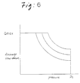
- load pressures P1 and P2 acting on pumps 2 and 3 are detected respectively through pressure detectors 20 and 21 of which the output voltages are increased proportionally to the pressure.
- step 42 the dischargeable amounts of flow Qmax1 and Qmax2 of pumps 2 and 3 corresponding to the load pressures are calculated from the output characteristics graphs(i.e., graphs 1, 2 and 3) which are determined by the output power of engine 1, as shown in Fig. 6.(step 42)
- the required flow amounts Qibk and Qibm of bucket cylinder 9 and boom cylinder 11 are supplied from the first pump 2, and the required amount of flow Qids of dipper stick cylinder 10 is supplied from the second pump 3.
- tilt angles ⁇ 1 and ⁇ 2 of the swash plate in pumps 2 and 3 detected by tilt angle detectors 15 and 16 are read out by A/D converter 32, and the number of pulses corresponding to the number of rotations per hour of engine 1 provided from rotation detector 14 incorporating a magnetic pick-up sensor, are counted by counter 34.
- Fig. 5a and Fig. 5b show a relationship among electrical currents i1 and i2 supplied to solenoid controlled proportional valves 7 and 8, the pilot pressure applied to pumps 2 and 3 from valves 7 and 8, and the actual discharge flow amount of pumps 2 and 3.
- Moving elements such as boom, bucket and dipper stick are coupled to one another by actuators 9, 10 and 11 with a plurality of links. Accordingly, by reading periodically relative angles ⁇ 1, ⁇ 2 and ⁇ 3 among the moving elements which are connected to actuators 9, 10 and 11, respectively, angular velocities ⁇ '1, ⁇ '2 and ⁇ '3 of moving elements are calculated. Depending on these data, operating displacement(or, in case of the hydraulic cylinder, a stroke of the cylinder) can be obtained.
- the actual operating flow amounts Qa1 and Qa2 of pumps 2 and 3 acting on actuators 9, 10 and 11 can be calculated by muliplying the volumes of actuators 9, 10 and 11 by linear velocities ⁇ '1, ⁇ '2 and ⁇ '3 of actuators 9, 10 and 11.
- actuators 9, 10 and 11 are hydraulic cylinders
- the method for detecting directly the strokes of the cylinders without detecting the relative velocities of the moving elements may be applied.
- actuators are hydraulic motors
- angular velocities ⁇ '1, ⁇ '2 and ⁇ '3 can be used for this purpose.
- step 45 actual operating flow amounts Qa1 and Qa2(hereinafter, referred to as "knuckle operating flow amount") acting actually on actuators 9, 10 and 11 are calculated.
- the proportional integral gain is used as the control gain in this embodiment, the combination of the proportional gain, the differential gain and the integral gain can be used as the control gain.
- the output flow amount compensated by the calculation as a final target discharge flow amount is converted to the output voltage and sent through D/A converter 39 of electronic control unit 22 to amplifier 40.
- amplifier 40 converts the output voltage to current signal, amplifies it, and drives solenoid controlled proportional valves 7 and 8.
- pilot pressure transmitted to pump regulators 5 and 6 from auxilliary pump 4 responds to the current signal provided from amplifier 40, controlling the tilt angle of the swash plate in pumps 2 and 3.
Landscapes
- Engineering & Computer Science (AREA)
- Mechanical Engineering (AREA)
- General Engineering & Computer Science (AREA)
- Physics & Mathematics (AREA)
- Computer Hardware Design (AREA)
- General Physics & Mathematics (AREA)
- Automation & Control Theory (AREA)
- Fluid Mechanics (AREA)
- Operation Control Of Excavators (AREA)
- Fluid-Pressure Circuits (AREA)
- Reciprocating Pumps (AREA)
- Control Of Positive-Displacement Pumps (AREA)
Claims (3)
- System zur Kontrolle einer Abgabeflußmenge einer Hydraulikpumpe in einem hydraulischem System mit einem Motor (1, 2) zum Antrieb der Pumpe (2, 3) und zumindest einem Hydraulikantrieb (9, 10, 11), der durch den Ölstrom von der Pumpe (2, 3) betrieben wird, umfassend:dadurch gekennzeichnet, daß das System darüber hinaus umfaßt:Einrichtungen (17, 18, 19) zur Erfassung des Betriebsversatzes der hydraulischen Antriebe (9, 10, 11);Betriebseinrichtungen (23) zur Ausgabe der Betriebsanweisungen eines Bedieners als elektrisches Signal;Einrichtungen (14) zur Erfassung der Anzahl von Rotationen des Motors (1) und zur Erzeugung einer Anzahl von Pulsen, entsprechend der Anzahl an Rotationen;Einrichtungen (15, 16, 2) zur Erfassung des Neigungswinkels einer Taumelplatte der Pumpe;Einrichtungen (20, 21) zur Erfassung des auf die Pumpen (2, 3) wirkenden Lastdruckes; undeine elektronische Kontrolleinheit (22) mit Einrichtungen (43) zur Berechnung der notwendigen Flußmengen (Qr1, Qr2) der Pumpen (2, 3), die notwendig sind, um eine vorbestimmte Operation auszuführen, aus den notwendigen Flußmengen (q1, q2, q3) der hydraulischen Antriebe (9, 10, 11), Einrichtungen (45) zur Bestimmung der tatsächlichen Abgabeflußmengen (Qe1, Qe2) der Pumpen (2, 3) welche auf die hydraulischen Antriebe (9, 10, 11) wirken, Einrichtungen (46) zur Bestimmung der tatsächlichen Betriebsflußmengen (Qa1, Qa2) der Pumpen (2, 3), Einrichtungen (47) zur Berechnung der Pumpenfluß Differenzen (dQe1, dQe2) zwischen den notwendigen Flußmengen (Qr1, Qr2) und den tatsächlichen Abgabeflußmengen (Qe1, Qe2) sowie der Antriebsflußdifferenzen (dQa1, dQa2) zwischen den notwendigen Flußmengen (Qr1, Qr2) und den tatsächlichen Betriebsflußmengen (Qa1, Qa2) der hydraulischen Antriebe (9, 10, 11), Einrichtungen (48) zu Berechnung der Zielflußmengen (Qo1, Qo2) der Pumpe (2, 3), aus den Pumpenflußdifferenzen (dQe1, dQe2) und den Antriebsflußdifferenzen (dQa1,dQa2), und Einrichtungen (49) zur Erzeugung von Ausgabespannungssignalen zur Steuerung der tatsächlichen Abgabeflußmengen (Qe1, Qe2) der Pumpen (2, 3), wobei die tatsächlichen Abgabeflußmengen (Qe1, Qe2) aus der Anzahl der Rotationen des Motors (1) und dem Neigungswinkel der Taumelplatte der Pumpe berechnet werden und wobei der Neigungswinkel der Taumelplatte der Pumpen und die tatsächlichen Betriebsflußmengen (Qa1, Qa2) aus dem Betriebsversatz der hydraulischen Antriebe (9, 10, 11) berechnet werden.
- System nach Anspruch 1, wobei die Kontrolleinrichtungen umfassen: Eine zentrale Rechnereinheit;zumindest eine Einrichtung zur Konvertierung der Analogsignale der Neigungswinkelerfassungseinrichtungen (15, 16) der Betriebsversatzerfassungseinrichtungen und der Lastdruckerfassungseinrichtungen in digitale Signale;eine Einrichtung zur Auswahl eines der digitalen Ausgangssignale von dem A/D-Wandler;eine Einrichtung zur Zählung zur Anzahl der Ausgangspulse der Rotationserfassungseinrichtungen;eine Einrichtung zur Speicherung eines Kontrollprogrammes, welches durch die zentrale Recheneinheit ausgeführt werden soll;zumindest eine Einrichtung zur Konvertierung des digitalen Ausgangssignales in Analogsignale; undzumindest einer Einrichtung (38, 40) zur Verstärkung der analogen Ausgangssignale sowie Zurverfügungsstellung der verstärkten Analogsignale als Kontrollsignale für die Pumpe (2, 3).
- Verfahren zur Berechnung einer Abgabeflußmenge einer hydraulischen Pumpe (2, 3) in einem hydraulischen System mit einem Motor (1) zum Antrieb der Pumpe (2, 3) und zumindest einem hydraulischem Antrieb (9, 10, 11) der durch einen Ölfluß von der Pumpe (2, 3) betrieben wird, gekennzeichnet durch die Schritte:Erfassung eines Betriebsversatzes des zumindest einen hydraulischen Antriebs (9, 10, 11), einer Anzahl von Rotationen des Motors (1) eines Neigungswinkels einer Taumelplatte der Pumpe (2, 3) und eines Lastdruckes der auf die Pumpe (2, 3) wirkt;Berechnung (41) einer notwendigen Flußmenge (q1, q2, q3) des zumindest einen hydraulischen Antriebes, der notwendig ist, um eine vorbestimmte Operation auszuführen;Berechnung (42) einer abgebbaren Flußmenge (Qe1, Qe2) der Pumpe (2, 3) aus dem Lastdruck, der auf sie wirkt;Berechnung (43, 2) einer notwendigen Abgabeflußmenge (Qr1, Qr2) der Pumpe (2, 3), der notwendig ist, um die vorbestimmte Operation auszuführen;Lesen (44) der Anzahl der Rotationen des Motors, des Neigungswinkels einer Taumelplatte der Pumpe (2, 3) und des Betriebsversatzes des zumindest einen hydraulischen Antriebes (9, 10, 11);Berechnung (45) einer tatsächlichen Abgabeflußmenge (Qe1, Qe2) der Pumpe (2, 3) aus der Anzahl der Rotationen und des Neigungswinkels;Berechnung (46) einer tatsächlichen Betriebsflußmenge (Qa1, Qa2) der Pumpe (2, 3), der auf den zumindest einen hydraulischen Antrieb (9, 10, 11) wirkt, aus dem Betriebsversatz des zumindest einen hydraulischen Antriebes (9, 10l, 11);Berechnung (47) einer Pumpenflußdifferenz (dQe1, dQe2), zwischen der notwendigen Flußmenge (Qr1, Qr2) und der tatsächlichen Abgabeflußmenge (Qe1, Qe2) der Pumpe (2, 3) sowie einer Antriebsflußdifferenz (dQa1, dQa2) zwischen der notwendigen Flußmenge (Qr1, Qr2) und der tatsächlichen Betriebsflußmenge (Qa1, Qa2) des zumindest einen hyderaulischen Antriebes;Berechnung (48) einer Zielabgabeflußmenge (Qo1, Qo2) der Pumpe (2, 3), die zur Ausführung der vorbestimmten Operation geeignet ist, aus der Relation der zwei Differenzen (dQe1, dQe2, dQe3, dQe4); undKonvertierung (49) der Zielabgabeflußmenge (Qo1, Qo2) in ein Spannungssignal, zur Verwendung als Kontrollsignal in dem hydraulischen System.
Applications Claiming Priority (2)
| Application Number | Priority Date | Filing Date | Title |
|---|---|---|---|
| KR9312454 | 1993-07-02 | ||
| KR1019930012454A KR0152300B1 (ko) | 1993-07-02 | 1993-07-02 | 유압펌프의 토출유량 제어방법 |
Publications (3)
| Publication Number | Publication Date |
|---|---|
| EP0632355A2 EP0632355A2 (de) | 1995-01-04 |
| EP0632355A3 EP0632355A3 (de) | 1995-02-15 |
| EP0632355B1 true EP0632355B1 (de) | 1998-04-08 |
Family
ID=19358661
Family Applications (1)
| Application Number | Title | Priority Date | Filing Date |
|---|---|---|---|
| EP94106424A Expired - Lifetime EP0632355B1 (de) | 1993-07-02 | 1994-04-25 | Verfahren und Vorrichtung zur Durchflusssteuerung einer Hydraulikpumpe |
Country Status (5)
| Country | Link |
|---|---|
| US (1) | US5659485A (de) |
| EP (1) | EP0632355B1 (de) |
| JP (1) | JP2807751B2 (de) |
| KR (1) | KR0152300B1 (de) |
| DE (1) | DE69409442T2 (de) |
Families Citing this family (18)
| Publication number | Priority date | Publication date | Assignee | Title |
|---|---|---|---|---|
| JP3497031B2 (ja) * | 1995-03-07 | 2004-02-16 | 日立建機株式会社 | 油圧ポンプ制御装置 |
| CN1137417C (zh) * | 1995-12-19 | 2004-02-04 | 日立建机株式会社 | 控制系统中修正输出的方法、控制系统和液压泵控制系统 |
| KR100378727B1 (ko) * | 1996-12-12 | 2003-06-19 | 신카타피라 미쓰비시 가부시키가이샤 | 건설기계의제어장치 |
| US7143016B1 (en) * | 2001-03-02 | 2006-11-28 | Rockwell Automation Technologies, Inc. | System and method for dynamic multi-objective optimization of pumping system operation and diagnostics |
| US6604601B2 (en) * | 2001-10-22 | 2003-08-12 | Biomet-Ross, Inc. | Lift truck drive train |
| US6848888B2 (en) * | 2002-12-12 | 2005-02-01 | Caterpillar Inc. | Sensor for a variable displacement pump |
| JP2006046292A (ja) * | 2004-08-09 | 2006-02-16 | Hitachi Constr Mach Co Ltd | 傾転制御信号の補正方法、傾転制御装置、建設機械および傾転制御信号補正用プログラム |
| JP4827789B2 (ja) * | 2007-04-18 | 2011-11-30 | カヤバ工業株式会社 | 油圧アクチュエータ速度制御装置 |
| EP2381115B1 (de) | 2008-12-24 | 2016-10-05 | Doosan Infracore Co., Ltd. | Hydraulikpumpensteuerung für eine baumaschine |
| US8113033B2 (en) * | 2009-06-08 | 2012-02-14 | Cnh America Llc | Method to calibrate a flow balance valve on a windrower draper header |
| US8594852B2 (en) * | 2010-02-22 | 2013-11-26 | Eaton Corporation | Device and method for controlling a fluid actuator |
| KR101754423B1 (ko) * | 2010-12-22 | 2017-07-20 | 두산인프라코어 주식회사 | 굴삭기의 유압펌프 제어방법 |
| US8935009B2 (en) | 2011-05-06 | 2015-01-13 | Caterpillar Inc. | Method and apparatus for controlling multiple variable displacement hydraulic pumps |
| EP2960529B1 (de) | 2013-02-19 | 2019-01-02 | Volvo Construction Equipment AB | Hydraulisches system für eine baumaschine mit einer schutzvorrichtung |
| DE102014001981B4 (de) * | 2014-02-17 | 2023-04-27 | Robert Bosch Gmbh | Dynamischer Sollwertausgleich bei drehzahlvariablen Verstellpumpen |
| KR101726509B1 (ko) * | 2015-09-02 | 2017-04-12 | 윤영원 | 중량물 리프트의 고압화 유압 동조 장치 |
| US10196131B2 (en) * | 2016-02-16 | 2019-02-05 | The Boeing Company | Hydraulic system and method for an aircraft flight control system |
| KR102027152B1 (ko) | 2018-06-21 | 2019-10-01 | 김대철 | 크레인용 펌프 어셈블리 |
Family Cites Families (14)
| Publication number | Priority date | Publication date | Assignee | Title |
|---|---|---|---|---|
| IN171213B (de) * | 1988-01-27 | 1992-08-15 | Hitachi Construction Machinery | |
| WO1990008263A1 (fr) * | 1989-01-18 | 1990-07-26 | Hitachi Construction Machinery Co., Ltd. | Unite de commande hydraulique pour engin de construction |
| JP2854899B2 (ja) * | 1989-01-18 | 1999-02-10 | 日立建機株式会社 | 油圧建設機械の駆動制御装置 |
| US5170625A (en) * | 1989-07-27 | 1992-12-15 | Hitachi Construction Machinery Co., Ltd. | Control system for hydraulic pump |
| JPH0379802A (ja) * | 1989-08-21 | 1991-04-04 | Hitachi Constr Mach Co Ltd | 土木・建設機械の油圧駆動装置 |
| US5174114A (en) * | 1990-02-28 | 1992-12-29 | Hitachi Construction Machinery Co., Ltd. | Hydraulic drive system for construction machine |
| JP2828490B2 (ja) * | 1990-06-19 | 1998-11-25 | 日立建機株式会社 | ロードセンシング油圧駆動回路の制御装置 |
| WO1992006306A1 (fr) * | 1990-09-28 | 1992-04-16 | Hitachi Construction Machinery Co., Ltd. | Systeme de commande pour pompe hydraulique |
| GB2251232B (en) * | 1990-09-29 | 1995-01-04 | Samsung Heavy Ind | Automatic actuating system for actuators of excavator |
| JP2866178B2 (ja) * | 1990-10-03 | 1999-03-08 | 日立建機株式会社 | 作業車両の油圧駆動装置 |
| GB2251962B (en) * | 1990-11-13 | 1995-05-24 | Samsung Heavy Ind | System for automatically controlling an operation of a heavy construction |
| JP2633095B2 (ja) * | 1991-02-08 | 1997-07-23 | 日立建機株式会社 | 油圧建設機械の油圧制御装置 |
| JP2854426B2 (ja) * | 1991-02-08 | 1999-02-03 | 日立建機株式会社 | 油圧走行作業車両の油圧駆動装置 |
| JPH07112836B2 (ja) * | 1991-06-14 | 1995-12-06 | 富士重工業株式会社 | 航空機の油圧操舵装置 |
-
1993
- 1993-07-02 KR KR1019930012454A patent/KR0152300B1/ko not_active Expired - Fee Related
-
1994
- 1994-01-28 JP JP6026180A patent/JP2807751B2/ja not_active Expired - Fee Related
- 1994-04-25 DE DE69409442T patent/DE69409442T2/de not_active Expired - Fee Related
- 1994-04-25 EP EP94106424A patent/EP0632355B1/de not_active Expired - Lifetime
- 1994-04-26 US US08/233,517 patent/US5659485A/en not_active Expired - Fee Related
Also Published As
| Publication number | Publication date |
|---|---|
| EP0632355A3 (de) | 1995-02-15 |
| KR950003643A (ko) | 1995-02-17 |
| EP0632355A2 (de) | 1995-01-04 |
| JPH0742199A (ja) | 1995-02-10 |
| DE69409442T2 (de) | 1998-11-26 |
| US5659485A (en) | 1997-08-19 |
| KR0152300B1 (ko) | 1998-10-15 |
| JP2807751B2 (ja) | 1998-10-08 |
| DE69409442D1 (de) | 1998-05-14 |
Similar Documents
| Publication | Publication Date | Title |
|---|---|---|
| EP0632355B1 (de) | Verfahren und Vorrichtung zur Durchflusssteuerung einer Hydraulikpumpe | |
| EP0545271B1 (de) | Vorrichtung zur Steuerung der Flüssigkeitsmenge einer hydraulischen Pumpe | |
| US4507057A (en) | Control system for hydraulic pumps of a civil machine | |
| US4510750A (en) | Circuit pressure control system for hydrostatic power transmission | |
| KR0145144B1 (ko) | 유압작업기의 유압구동장치 | |
| US6623247B2 (en) | Method and apparatus for controlling a variable displacement hydraulic pump | |
| EP0667451B1 (de) | Regelungsanordnung einer hydraulischen pumpe für baumaschinen | |
| EP2660477B1 (de) | Verfahren zur steuerung des durchflusses einer hydraulischen pumpe mit veränderlicher fördermenge für eine konstruktionsvorrichtung | |
| EP0605724A1 (de) | Umschalteinrichtung für feinarbeits-programm für einen hydraulikbagger | |
| US5629849A (en) | Method for controlling operation of repeated work of excavator vehicle | |
| JP2511925B2 (ja) | 建設機械のエンジン回転数制御装置 | |
| EP0780522A1 (de) | Regelsystem für das Drehmoment einer Pumpe | |
| CN212845447U (zh) | 一种测量行走马达转速的结构 | |
| US5879136A (en) | Electrohydraulic adjustable pump | |
| EP1584755B1 (de) | Verfahren zur Hydraulikpumpenförderstromkompensation in Baumaschinen bei Steuerhebelneutralstellung | |
| US6499295B1 (en) | Hydro-transformer | |
| WO2000055508A1 (en) | Control system for a hydraulic transformer | |
| KR950003644A (ko) | 유압식 건설기계의 제어장치 및 방법 | |
| JPH0352279Y2 (de) | ||
| KR960004630B1 (ko) | 유압기계의 출력제어장치 | |
| JPS6115305B2 (de) | ||
| JPH10220406A (ja) | 加工機械の制御装置 | |
| JP2539370B2 (ja) | 原動機と油圧ポンプを含む系の駆動装置 | |
| KR950004020B1 (ko) | 자동유량조절장치 | |
| JPH09291906A (ja) | 油圧機械のセンサ |
Legal Events
| Date | Code | Title | Description |
|---|---|---|---|
| PUAI | Public reference made under article 153(3) epc to a published international application that has entered the european phase |
Free format text: ORIGINAL CODE: 0009012 |
|
| PUAL | Search report despatched |
Free format text: ORIGINAL CODE: 0009013 |
|
| AK | Designated contracting states |
Kind code of ref document: A2 Designated state(s): DE FR GB IT |
|
| AK | Designated contracting states |
Kind code of ref document: A3 Designated state(s): DE FR GB IT |
|
| 17P | Request for examination filed |
Effective date: 19950330 |
|
| 17Q | First examination report despatched |
Effective date: 19960115 |
|
| GRAG | Despatch of communication of intention to grant |
Free format text: ORIGINAL CODE: EPIDOS AGRA |
|
| GRAG | Despatch of communication of intention to grant |
Free format text: ORIGINAL CODE: EPIDOS AGRA |
|
| GRAH | Despatch of communication of intention to grant a patent |
Free format text: ORIGINAL CODE: EPIDOS IGRA |
|
| GRAH | Despatch of communication of intention to grant a patent |
Free format text: ORIGINAL CODE: EPIDOS IGRA |
|
| GRAA | (expected) grant |
Free format text: ORIGINAL CODE: 0009210 |
|
| AK | Designated contracting states |
Kind code of ref document: B1 Designated state(s): DE FR GB IT |
|
| REF | Corresponds to: |
Ref document number: 69409442 Country of ref document: DE Date of ref document: 19980514 |
|
| ITF | It: translation for a ep patent filed | ||
| ET | Fr: translation filed | ||
| PLBE | No opposition filed within time limit |
Free format text: ORIGINAL CODE: 0009261 |
|
| STAA | Information on the status of an ep patent application or granted ep patent |
Free format text: STATUS: NO OPPOSITION FILED WITHIN TIME LIMIT |
|
| REG | Reference to a national code |
Ref country code: FR Ref legal event code: TP |
|
| PG25 | Lapsed in a contracting state [announced via postgrant information from national office to epo] |
Ref country code: FR Free format text: LAPSE BECAUSE OF NON-PAYMENT OF DUE FEES Effective date: 19990226 |
|
| GBPC | Gb: european patent ceased through non-payment of renewal fee |
Effective date: 19980708 |
|
| 26N | No opposition filed | ||
| REG | Reference to a national code |
Ref country code: FR Ref legal event code: ST |
|
| REG | Reference to a national code |
Ref country code: GB Ref legal event code: 732E |
|
| RAP2 | Party data changed (patent owner data changed or rights of a patent transferred) |
Owner name: VOLVO CONSTRUCTION EQUIPMENT KOREA CO., LTD. |
|
| REG | Reference to a national code |
Ref country code: GB Ref legal event code: 728V |
|
| REG | Reference to a national code |
Ref country code: GB Ref legal event code: 728Y |
|
| REG | Reference to a national code |
Ref country code: GB Ref legal event code: IF02 |
|
| REG | Reference to a national code |
Ref country code: GB Ref legal event code: 732E |
|
| REG | Reference to a national code |
Ref country code: FR Ref legal event code: TP |
|
| PGFP | Annual fee paid to national office [announced via postgrant information from national office to epo] |
Ref country code: FR Payment date: 20030408 Year of fee payment: 10 |
|
| PGFP | Annual fee paid to national office [announced via postgrant information from national office to epo] |
Ref country code: DE Payment date: 20070419 Year of fee payment: 14 |
|
| PGFP | Annual fee paid to national office [announced via postgrant information from national office to epo] |
Ref country code: GB Payment date: 20070425 Year of fee payment: 14 |
|
| PGFP | Annual fee paid to national office [announced via postgrant information from national office to epo] |
Ref country code: IT Payment date: 20070608 Year of fee payment: 14 |
|
| GBPC | Gb: european patent ceased through non-payment of renewal fee |
Effective date: 20080425 |
|
| PG25 | Lapsed in a contracting state [announced via postgrant information from national office to epo] |
Ref country code: DE Free format text: LAPSE BECAUSE OF NON-PAYMENT OF DUE FEES Effective date: 20081101 |
|
| PG25 | Lapsed in a contracting state [announced via postgrant information from national office to epo] |
Ref country code: GB Free format text: LAPSE BECAUSE OF NON-PAYMENT OF DUE FEES Effective date: 20080425 |
|
| PG25 | Lapsed in a contracting state [announced via postgrant information from national office to epo] |
Ref country code: IT Free format text: LAPSE BECAUSE OF NON-PAYMENT OF DUE FEES Effective date: 20080425 |