EP0632504B1 - Dispositif semi-conducteur avec contact ohmique en BeTe-ZnSe à bande interdite graduelle sur semi-conducteur II-VI - Google Patents
Dispositif semi-conducteur avec contact ohmique en BeTe-ZnSe à bande interdite graduelle sur semi-conducteur II-VI Download PDFInfo
- Publication number
- EP0632504B1 EP0632504B1 EP94201871A EP94201871A EP0632504B1 EP 0632504 B1 EP0632504 B1 EP 0632504B1 EP 94201871 A EP94201871 A EP 94201871A EP 94201871 A EP94201871 A EP 94201871A EP 0632504 B1 EP0632504 B1 EP 0632504B1
- Authority
- EP
- European Patent Office
- Prior art keywords
- layer
- semiconductor
- znse
- bete
- semiconductor device
- Prior art date
- Legal status (The legal status is an assumption and is not a legal conclusion. Google has not performed a legal analysis and makes no representation as to the accuracy of the status listed.)
- Expired - Lifetime
Links
- 239000004065 semiconductor Substances 0.000 title claims description 57
- 229910015894 BeTe Inorganic materials 0.000 claims description 58
- SBIBMFFZSBJNJF-UHFFFAOYSA-N selenium;zinc Chemical compound [Se]=[Zn] SBIBMFFZSBJNJF-UHFFFAOYSA-N 0.000 claims description 51
- 239000000758 substrate Substances 0.000 claims description 17
- 239000000203 mixture Substances 0.000 claims description 13
- 238000005253 cladding Methods 0.000 claims description 9
- 239000000463 material Substances 0.000 claims description 8
- 229910052751 metal Inorganic materials 0.000 claims description 6
- 239000002184 metal Substances 0.000 claims description 6
- 239000010931 gold Substances 0.000 claims description 4
- PCHJSUWPFVWCPO-UHFFFAOYSA-N gold Chemical compound [Au] PCHJSUWPFVWCPO-UHFFFAOYSA-N 0.000 claims description 3
- 229910052737 gold Inorganic materials 0.000 claims description 3
- 229910052738 indium Inorganic materials 0.000 claims description 2
- APFVFJFRJDLVQX-UHFFFAOYSA-N indium atom Chemical compound [In] APFVFJFRJDLVQX-UHFFFAOYSA-N 0.000 claims description 2
- BASFCYQUMIYNBI-UHFFFAOYSA-N platinum Chemical compound [Pt] BASFCYQUMIYNBI-UHFFFAOYSA-N 0.000 claims 2
- 229910052697 platinum Inorganic materials 0.000 claims 1
- 239000010410 layer Substances 0.000 description 87
- 239000011701 zinc Substances 0.000 description 42
- 229910001218 Gallium arsenide Inorganic materials 0.000 description 16
- 230000004888 barrier function Effects 0.000 description 7
- 238000010586 diagram Methods 0.000 description 7
- 239000000370 acceptor Substances 0.000 description 6
- 238000000034 method Methods 0.000 description 6
- 238000001451 molecular beam epitaxy Methods 0.000 description 6
- 229910007709 ZnTe Inorganic materials 0.000 description 5
- 150000001875 compounds Chemical class 0.000 description 5
- 230000003287 optical effect Effects 0.000 description 3
- 230000015572 biosynthetic process Effects 0.000 description 2
- 229910052793 cadmium Inorganic materials 0.000 description 2
- BDOSMKKIYDKNTQ-UHFFFAOYSA-N cadmium atom Chemical compound [Cd] BDOSMKKIYDKNTQ-UHFFFAOYSA-N 0.000 description 2
- 230000001627 detrimental effect Effects 0.000 description 2
- 239000002019 doping agent Substances 0.000 description 2
- 230000000694 effects Effects 0.000 description 2
- 238000002360 preparation method Methods 0.000 description 2
- 238000005204 segregation Methods 0.000 description 2
- 239000002356 single layer Substances 0.000 description 2
- 239000000243 solution Substances 0.000 description 2
- 229910052725 zinc Inorganic materials 0.000 description 2
- 102000010970 Connexin Human genes 0.000 description 1
- 108050001175 Connexin Proteins 0.000 description 1
- 239000004642 Polyimide Substances 0.000 description 1
- HCHKCACWOHOZIP-UHFFFAOYSA-N Zinc Chemical compound [Zn] HCHKCACWOHOZIP-UHFFFAOYSA-N 0.000 description 1
- 230000009471 action Effects 0.000 description 1
- 238000013459 approach Methods 0.000 description 1
- 238000004364 calculation method Methods 0.000 description 1
- 230000008859 change Effects 0.000 description 1
- 238000000576 coating method Methods 0.000 description 1
- 239000013078 crystal Substances 0.000 description 1
- 238000005516 engineering process Methods 0.000 description 1
- 210000003976 gap junction Anatomy 0.000 description 1
- 230000005525 hole transport Effects 0.000 description 1
- 238000002347 injection Methods 0.000 description 1
- 239000007924 injection Substances 0.000 description 1
- 239000012212 insulator Substances 0.000 description 1
- 238000012886 linear function Methods 0.000 description 1
- 238000004519 manufacturing process Methods 0.000 description 1
- 238000005259 measurement Methods 0.000 description 1
- 238000012986 modification Methods 0.000 description 1
- 230000004048 modification Effects 0.000 description 1
- 150000002831 nitrogen free-radicals Chemical class 0.000 description 1
- 229920001721 polyimide Polymers 0.000 description 1
- 238000012545 processing Methods 0.000 description 1
- 238000012887 quadratic function Methods 0.000 description 1
- 230000009467 reduction Effects 0.000 description 1
- 229910052950 sphalerite Inorganic materials 0.000 description 1
- 230000000638 stimulation Effects 0.000 description 1
- 238000003786 synthesis reaction Methods 0.000 description 1
- 239000011592 zinc chloride Substances 0.000 description 1
- JIAARYAFYJHUJI-UHFFFAOYSA-L zinc dichloride Chemical compound [Cl-].[Cl-].[Zn+2] JIAARYAFYJHUJI-UHFFFAOYSA-L 0.000 description 1
- 229910052984 zinc sulfide Inorganic materials 0.000 description 1
Images

Classifications
-
- B—PERFORMING OPERATIONS; TRANSPORTING
- B82—NANOTECHNOLOGY
- B82Y—SPECIFIC USES OR APPLICATIONS OF NANOSTRUCTURES; MEASUREMENT OR ANALYSIS OF NANOSTRUCTURES; MANUFACTURE OR TREATMENT OF NANOSTRUCTURES
- B82Y20/00—Nanooptics, e.g. quantum optics or photonic crystals
-
- H—ELECTRICITY
- H01—ELECTRIC ELEMENTS
- H01S—DEVICES USING THE PROCESS OF LIGHT AMPLIFICATION BY STIMULATED EMISSION OF RADIATION [LASER] TO AMPLIFY OR GENERATE LIGHT; DEVICES USING STIMULATED EMISSION OF ELECTROMAGNETIC RADIATION IN WAVE RANGES OTHER THAN OPTICAL
- H01S5/00—Semiconductor lasers
- H01S5/04—Processes or apparatus for excitation, e.g. pumping, e.g. by electron beams
- H01S5/042—Electrical excitation ; Circuits therefor
- H01S5/0421—Electrical excitation ; Circuits therefor characterised by the semiconducting contacting layers
-
- H—ELECTRICITY
- H01—ELECTRIC ELEMENTS
- H01S—DEVICES USING THE PROCESS OF LIGHT AMPLIFICATION BY STIMULATED EMISSION OF RADIATION [LASER] TO AMPLIFY OR GENERATE LIGHT; DEVICES USING STIMULATED EMISSION OF ELECTROMAGNETIC RADIATION IN WAVE RANGES OTHER THAN OPTICAL
- H01S5/00—Semiconductor lasers
- H01S5/30—Structure or shape of the active region; Materials used for the active region
- H01S5/32—Structure or shape of the active region; Materials used for the active region comprising PN junctions, e.g. hetero- or double- heterostructures
- H01S5/327—Structure or shape of the active region; Materials used for the active region comprising PN junctions, e.g. hetero- or double- heterostructures in AIIBVI compounds, e.g. ZnCdSe-laser
-
- H—ELECTRICITY
- H10—SEMICONDUCTOR DEVICES; ELECTRIC SOLID-STATE DEVICES NOT OTHERWISE PROVIDED FOR
- H10D—INORGANIC ELECTRIC SEMICONDUCTOR DEVICES
- H10D62/00—Semiconductor bodies, or regions thereof, of devices having potential barriers
- H10D62/80—Semiconductor bodies, or regions thereof, of devices having potential barriers characterised by the materials
- H10D62/82—Heterojunctions
- H10D62/826—Heterojunctions comprising only Group II-VI materials heterojunctions, e.g. CdTe/HgTe heterojunctions
-
- H—ELECTRICITY
- H10—SEMICONDUCTOR DEVICES; ELECTRIC SOLID-STATE DEVICES NOT OTHERWISE PROVIDED FOR
- H10D—INORGANIC ELECTRIC SEMICONDUCTOR DEVICES
- H10D64/00—Electrodes of devices having potential barriers
- H10D64/60—Electrodes characterised by their materials
- H10D64/62—Electrodes ohmically coupled to a semiconductor
-
- H—ELECTRICITY
- H01—ELECTRIC ELEMENTS
- H01S—DEVICES USING THE PROCESS OF LIGHT AMPLIFICATION BY STIMULATED EMISSION OF RADIATION [LASER] TO AMPLIFY OR GENERATE LIGHT; DEVICES USING STIMULATED EMISSION OF ELECTROMAGNETIC RADIATION IN WAVE RANGES OTHER THAN OPTICAL
- H01S5/00—Semiconductor lasers
- H01S5/30—Structure or shape of the active region; Materials used for the active region
- H01S5/34—Structure or shape of the active region; Materials used for the active region comprising quantum well or superlattice structures, e.g. single quantum well [SQW] lasers, multiple quantum well [MQW] lasers or graded index separate confinement heterostructure [GRINSCH] lasers
- H01S5/347—Structure or shape of the active region; Materials used for the active region comprising quantum well or superlattice structures, e.g. single quantum well [SQW] lasers, multiple quantum well [MQW] lasers or graded index separate confinement heterostructure [GRINSCH] lasers in AIIBVI compounds, e.g. ZnCdSe- laser
Definitions
- the present invention relates to semiconductor devices, in particular to diode lasers comprising Group II-IV compound semiconductors.
- ZnSe-based blue-green lasers Perhaps the most important obstacle preventing widespread use of these ZnSe-based blue-green lasers and maturing of this technology is the difficulty in fabricating low resistivity Ohmic contacts to p-type, normal thickness ZnSe-based cladding layers, (eg, ZnSe, ZnS x Se 1-x and Zn 1-x Mg x S y Se 1-y ).
- Gold (Au) electrodes which are typically involved in the formation of electrical contacts, form a Schottky barrier on p-ZnSe in excess of 1.0 eV and no metal that has a work function that is high enough to lower that barrier has been found.
- ZnSe:N contact layers by lowering the substrate temperature during molecular beam epitaxy growth to 150°C, and using a cracked Se source (J. Qui et al, Proceedings of VII MBE Conference Schwabisch Gemund, Germany, Aug. 24-28,1992); a ZnSe/ZnTe multilayer structure used for a contact layer to achieve a graded band gap effect from p-ZnSe to p-ZnTe (Y. Fan et al, Appl. Phys. Lett.
- ZnTe-ZnSe layers have a higher refractive index than the active region formed by ZnSe or ZnCd x Se 1-x layers, which has a detrimental effect on the optical confinement in the active region of the laser.
- an extra-thick p-cladding layer would be required which further complicates matters since it is likely to increase the voltage threshold for laser emission.
- An object of the present invention is to provide a Semiconductors device in particular a Semiconductor diodelaser, with II-VI layers, e.g. ZnSe-based layers, that are free of the problems met heretofore by prior art structures.
- Another object of the invention is to provide devices with an ohmic contact to ZnSe-based layers by a method in which the valence band affinity of the semiconductor near the surface is reduced by use of a graded gap semiconductor layer.
- Yet another object is to provide diode lasers derived from such Ohmic contacts and most preferably lasers of the blue-green type.
- BeTe is utilized in a graded band gap layer for Ohmic contact to p-type ZnSe, based semiconductors. Due to the close lattice match to GaAs and ZnSe and grown character, Be x Zn 1-x Te y Se 1-y graded band gap layers are ideal for Ohmic contact to p-type ZnSe based and other II-VI compound semiconductors. It is to be noted that a BeTe layer is known from JP-4-63479. According to this prior art docoument, the BeTe layer acts as an injection layer for a light-emitting layer.
- the conductivity type of the BeTe layer has to be opposite to the conductivity type of the light-emitting layer and a graded composition of the BeTe layer serves no purpose.
- a graded composition of the BeTe layer serves no purpose.
- Such contacts such as Be x Zn 1-x Te x Se 1-x wherein x is a number selected from the range of 0 to 1.
- the compositions of the invention will be described with reference to the composition Be x Zn 1-x Te x Se 1-x .
- BeTe-ZnSe graded gap semiconductor layers are provided for application as ohmic contacts to p- type ZnSe, ZnS x Se 1-x , Zn 1-x Cd x S, Zn 1-x Cd x S y Se 1-y , Zn 1-x Mg x S y Se 1-y (wherein x and y are a number selected from 0 to 1), and other II-VI compound semiconductors used in lasers grown on GaAs substrates. Due to the close lattice match to GaAs substrate, (BeTe) x (ZnSe) 1-x contacts allow for the entire device structure to be grown within the pseudomorphic limit.
- the band gap energy of BeTe is higher than ZnSe
- the refractive index of BeTe is expected to be lower than ZnSe or ZnCd x Se 1-x , and optical confinement around an active region in a blue or blue-green laser will not be affected by these contacts.
- the invention uses BeTe to form a compositional grading to ZnSe or other II - VI compound semiconductor lattice matched to GaAs.
- This lattice matching may prove to be critical for implementation onto room temperature operative diode lasers.
- the BeTe - ZnSe graded composition ohmic contacts are believed to be a practical and necessary solution for blue lasers grown on GaAs substrates.
- a large barrier in valence band at the BeTe/ZnSe heterojunction would suppress transport of holes fron BeTe to ZnSe.
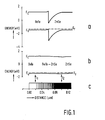
- a large valence band offset in abrupt BeTe/ZnSe heterojunction can almost entirely be removed if linearly graded heterojunction is used, as shown in Fig. 1b in which grading takes place from 200 to 1000 ⁇ which is indicated by arrows.
- an epitaxial growth of BeTe-ZnSe graded layer is preferably done by digital technique in which layers of the graded components are alternately grown in predetermined thicknesses and numbers as represented by (BeTe) x (ZnSe) 1-x .
- the graded gap junction is divided into 21 segments, each 40A wide.
- the second segment contains 2 ⁇ of p-ZnSe and 38 ⁇ of p-BeTe;
- the third segment has 4 ⁇ of p-ZnSe and 36 ⁇ of p-BeTe, etc.
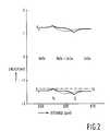
- Figs. 2 and 3 there are illustrated the energy band diagram for linear (solid line) and quadratic (dashed line) Be x Zn 1-x Te x Se 1-x graded junctions of several widths.
- the cusps in the valence band appearing in linearly graded junction near the edges of the linearly graded Be x Zn 1-x Te x Se 1-x junction at 1 1 and 1 2 act on a hole transport as a trap and a barrier, respectively, i.e. the cusps act as a well and a barrier for mobile holes, respectively.
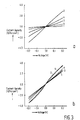
- the detrimental influence of the barrier around 1 2 on the contact resistance is more significant, and can be reduced by introducing quadratic grading through the entire Be x Zn 1-x Te x Se 1-x layer, as illustrated in Fig. 2. This becomes quite apparent from the comparison of the calculated current-voltage characteristics of the quadratically and linearly graded contacts shown in Fig. 3 by curves 1 and 5.
- the continuous lines correspond to linearly graded p-Be x Zn 1-x Te x Se 1-x junctions doped uniformly at 1 and 2x10 18 cm -3 (curves 1 and 2 ,respectively), and linearly doped from 10 18 cm -3 at 1 2 , to 5 and 10x10 18 cm -3 at 1 1 (curves 3 and 4, respectively).
- the dotted line in Fig. 3 (curve 5) corresponds to quadratically graded Be x Zn 1-x Te x Se 1-x layers doped uniformly with acceptors at 1x10 18 cm -3 level.
- an increase in doping level of p-ZnSe to 2x10 18 cm -3 lowers the contact resistivity of Be x Zn 1-x Te x Se 1-x linearly graded layers more significantly than an increase in doping in p-BeTe, even at as high a level as 1x10 19 cm -3 . Therefore, if an upper limit of p-ZnSe doping is selected to be 1x10 18 cm -3 , the junction width, w J , of the Be x Zn 1-x Te x Se 1-x layer should be increased.
- the contact resistance of the linearly graded p-Be x Zn 1-x Te x Se 1-x layers as a function of the junction width w j , for uniform doping at 1x10 18 cm -3 is illustrated in Fig. 4.
- the structure included 200 ⁇ p-BeTe and 300-900 ⁇ p-Be x Zn 1-x Te x Se 1-x where the total thickness will still allow for pseudomorphic growth of these layers on GaAs substrate and for the production of blue laser structures entirely lattice matched to GaAs substrate.
- the graded Be x Zn 1-x Te x Se 1-x layer may be utilized to fabricate blue-green lasers according to methods such as, for example that described in Gaines et al, Appl. Phys. Lett.,62 ,62(20), pp.2462 (1993) and in Gaines et al, copending U.S. Application Ser.No. 07/997,988 filed December.
- Particularly preferred is a structure as illustrated in Fig.5 which illustrates a laser diode 10 which may be generally be grown by molecular beam epitaxy (MBE) on a GaAs substrate 20 and includes an ohmic contact layer 16 which comprises a graded band gap Be x Zn 1-x Te x Se 1-x composition of the invention.
- MBE molecular beam epitaxy
- a bottom waveguide cladding layer 22 of ZnS x Se 1-x which by its doping is n-type.
- Grown atop cladding layer 22 is a layer of ZnSe 24 which forms the bottom half of the waveguide.
- Grown on layer 24 is an active region 26 consisting of three undoped Cd u Zn 1-u Se quantum wells separated by two undoped ZnSe spacer regions.
- Grown on active region 26 is a p-ZnSe guiding layer 28.
- Grown on layer 28 is a p- ZnS z Se 1-z top cladding layer 30.
- an ohmic contact layer 16 which comprises a graded band gap Be x Zn 1-x Te x Se 1-x part 17 and a BeTe part 18 according to the invention.
- a polyimide insulator layer 32 with openings 33 is applied and contacts to part 18 of the contact layer 16 and the GaAs substrate were made with gold layers 34, 35.
- Source materials may be selected from those well known in the art and are preferably Zn, Se, Cd, and ZnS.
- the p- and n- type dopants may be N, excited by a plasma source, and Cl (from ZnCl 2 ), respectively.
- Doping levels and processing may be as described in said copending application, i.e. the doping levels for the layers 22, 24, 28 and 30 are approximately 1x10 18 , 3x10 17 , and 2x10 17 cm -3 , respectively.
- the doping level in the p- ZnS z Se 1-z layer 30 may be 2x10 17 cm -3 and that in the graded band gap composition layer 16 may be approximately at the levels discussed above with respect to Figs. 3 and 4, i.e. doping will vary depending on the grading and the particular area of the grading, the junction width, etc, and is preferably at least 1x10 18 cm -3 .
- each of the layers is grown in a manner so as to minimize the loss of light in absorbing layers and maximize the amount of light in the active region with specific thicknesses being illustrated in Fig. 5 for purposes of illustration only.
- useful devices may be made with a n-type cladding layer 22 of 2.0 microns, an guiding layers 24 and 28, including the quantum well region 26 having a thickness of about 60 A with about 110 ⁇ thick ZnSe spacers in between,has a total thickness of approximately 1 micron.
- the p-type top cladding layer 30 and the p-type graded band gap contact layer 16 have a total thickness of about 1.5 micron, the graded contact layer 16 having a thickness of approximately 400 to 800 ⁇ .
- Suitable ranges for u are from 0 to 1.0, z from 0 to 0.1, y from 0 to 1 and x from 0 to 1, with x and y being selected to provide lattice matching to GaAs.
- facet coatings may be applied to mirrors 36, 38 of the device.
- the cleaving of the device to its useful length, here about 500 ⁇ m provides the necessary "mirror" action to provide laser stimulation.
- the light output may be shifted towards blue by reducing the thickness of active region 26 and/or by reducing the cadmium content of this layer (u approaches 0).
- the substrate and lower layers are n-type with the upper layers being p-type.
- An analogous structure can be grown with the lower layers p-type and the upper layers n-type.
Landscapes
- Physics & Mathematics (AREA)
- Optics & Photonics (AREA)
- Engineering & Computer Science (AREA)
- Condensed Matter Physics & Semiconductors (AREA)
- General Physics & Mathematics (AREA)
- Electromagnetism (AREA)
- Nanotechnology (AREA)
- Chemical & Material Sciences (AREA)
- Biophysics (AREA)
- Crystallography & Structural Chemistry (AREA)
- Life Sciences & Earth Sciences (AREA)
- Semiconductor Lasers (AREA)
- Led Devices (AREA)
Claims (10)
- Dispositif à semi-conducteur (10) comportant un corps semi-conducteur comprenant un substrat semi-conducteur (20) et, sur celui-ci, une structure de couche semi-conductrice comprenant une couche semi-conductrice (30) d'un premier type de conductivité, cette couche semi-conductrice comprenant un matériau semi-conducteur AIIBVI, et une couche métallique (34) sur la structure de couche semi-conductrice formant un contact avec le dispositif semi-conducteur, caractérisé en ce que le dispositif comprend entre la couche semi-conductrice et la couche métallique, une couche semi-conductrice supplémentaire (16) du premier type de conductivité comprenant du BeTe et ayant, dans la direction allant de la couche métallique (34) vers la couche semi-conductrice (30), une composition graduelle allant du BeTe jusqu'au matériau AIIBVI de la couche semi-conductrice (30).
- Dispositif à semi-conducteur suivant la revendication 1, caractérisé en ce que la couche semi-conductrice supplémentaire (16) comprend du BexA1-xTeyB1-y où x et y se situent dans l'intervalle de 0 à 1 et sont choisis de manière à assurer la concordance de réseau avec le substrat semi-conducteur (20).
- Dispositif à semi-conducteur suivant la revendication 1 ou 2, caractérisé en ce que la couche semi-conductrice supplémentaire (16) comprend une pluralité de couches de BeTe et du matériau semi-conducteur AIIBVI de la couche servi-conductrice (30) formées par croissance en alternance, couche semi-conductrice (30) de façon que la composition graduelle de la couche semi-conductrice supplémentaire (16) soit BexA1-xTexB1-x où x et 1-x sont déterminés par l'épaisseur relative de deux couches de BeTe et AIIBVI consécutives, laquelle épaisseur relative est rendue graduelle pour rendre la composition graduelle.
- Dispositif à semi-conducteur suivant la revendication 3, caractérisé en ce que le matériau semi-conducteur AIIBVI comprend du ZnSe et la couche semi-conductrice supplémentaire (16) comprend 21 segments chacun d'une épaisseur d'environ 4 nm, le nième segment comprenant une couche d'environ (n-1)*0,2 nm de ZnSe et une couche d'environ (4 - (n-1)*0,2) nm de BeTe.
- Dispositif à semi-conducteur suivant la revendication 3, caractérisé en ce que le matériau semi-conducteur AIIBVI comprend du ZnSe et la couche semi-conductrice supplémentaire (16) a une épaisseur d'environ 82 nm et comprend 18 segments, le nième segment comprenant (n-1) monocouches de ZnSe et (18-n) monocouches de BeTe.
- Dispositif à semi-conducteur suivant l'une quelconque des revendications précédentes, caractérisé en ce que la couche semi-conductrice (30) et la couche semi-conductrice supplémentaire (16) sont de type de conductivité p.
- Dispositif à semi-conducteur suivant la revendication 6, caractérisé en ce que le contact avec le dispositif semi-conducteur a une résistivité de contact (ρ) inférieure à environ 10-4 Ωcm2 à un taux de dopage en accepteurs d'environ 1x1018 cm-3.
- Dispositif à semi-conducteur suivant l'une quelconque des revendications précédentes, caractérisé en ce que la couche de métal (34) comprend de l'indium, de l'or ou du platine.
- Dispositif à semi-conducteur suivant l'une quelconque des revendications précédentes, caractérisé en ce que dispositif à semi-conducteur est une diode laser à semi-conducteur AIIBVI.
- Dispositif à semi-conducteur suivant la revendication 9, caractérisé en ce que le substrat semi-conducteur (20) est d'un second type de conductivité opposé au premier type de conductivité, et la structure de couches semi-conductrices comprend, entre le substrat (20) et la couche semi-conductrice supplémentaire (16), dans cet ordre, une première couche de gainage (22) du second type de conductivité, une première couche guide (24) du second type de conductivité, une couche active (26), une seconde couche guide (28) du premier type de conductivité et une seconde couche de gainage (30) du premier type de conductivité.
Applications Claiming Priority (2)
| Application Number | Priority Date | Filing Date | Title |
|---|---|---|---|
| US08/087,307 US5422902A (en) | 1993-07-02 | 1993-07-02 | BeTe-ZnSe graded band gap ohmic contact to p-type ZnSe semiconductors |
| US87307 | 1993-07-02 |
Publications (3)
| Publication Number | Publication Date |
|---|---|
| EP0632504A2 EP0632504A2 (fr) | 1995-01-04 |
| EP0632504A3 EP0632504A3 (fr) | 1995-11-15 |
| EP0632504B1 true EP0632504B1 (fr) | 1997-09-10 |
Family
ID=22204390
Family Applications (1)
| Application Number | Title | Priority Date | Filing Date |
|---|---|---|---|
| EP94201871A Expired - Lifetime EP0632504B1 (fr) | 1993-07-02 | 1994-06-29 | Dispositif semi-conducteur avec contact ohmique en BeTe-ZnSe à bande interdite graduelle sur semi-conducteur II-VI |
Country Status (4)
| Country | Link |
|---|---|
| US (1) | US5422902A (fr) |
| EP (1) | EP0632504B1 (fr) |
| JP (1) | JPH0758417A (fr) |
| DE (1) | DE69405486T2 (fr) |
Families Citing this family (14)
| Publication number | Priority date | Publication date | Assignee | Title |
|---|---|---|---|---|
| WO1994015369A1 (fr) * | 1992-12-22 | 1994-07-07 | Research Corporation Technologies, Inc. | Dispositifs semi-conducteurs electroluminescents composes des groupes ii a vi et contact ohmique a cet effet |
| JP3461611B2 (ja) * | 1995-03-24 | 2003-10-27 | 正紀 村上 | Ii−vi族化合物半導体装置及びその製造方法 |
| DE19542241C2 (de) * | 1995-11-13 | 2003-01-09 | Siemens Ag | Optoelektronisches Bauelement in II-VI-Halbleitermaterial |
| US5818859A (en) * | 1996-06-27 | 1998-10-06 | Minnesota Mining And Manufacturing Company | Be-containing II-VI blue-green laser diodes |
| US5841802A (en) * | 1996-08-30 | 1998-11-24 | Mcdonnell Douglas Corporation | Multiple, isolated strained quantum well semiconductor laser |
| US6090637A (en) | 1997-02-13 | 2000-07-18 | 3M Innovative Properties Company | Fabrication of II-VI semiconductor device with BeTe buffer layer |
| US5767534A (en) * | 1997-02-24 | 1998-06-16 | Minnesota Mining And Manufacturing Company | Passivation capping layer for ohmic contact in II-VI semiconductor light transducing device |
| DE19729186A1 (de) * | 1997-07-08 | 1999-01-14 | Siemens Ag | Verfahren zum Herstellen eines II-VI-Halbleiter-Bauelements |
| DE19729396A1 (de) * | 1997-07-09 | 1999-01-14 | Siemens Ag | Elektrischer Kontakt für ein II-VI-Halbleiterbauelement und Verfahren zum Herstellen des elektrischen Kontaktes |
| US5963573A (en) * | 1997-08-25 | 1999-10-05 | 3M Innovative Properties Company | Light absorbing layer for II-VI semiconductor light emitting devices |
| US6087725A (en) * | 1997-09-29 | 2000-07-11 | Matsushita Electric Industrial Co., Ltd. | Low barrier ohmic contact for semiconductor light emitting device |
| US6373188B1 (en) * | 1998-12-22 | 2002-04-16 | Honeywell International Inc. | Efficient solid-state light emitting device with excited phosphors for producing a visible light output |
| DE10024924A1 (de) * | 2000-05-19 | 2001-11-29 | Osram Opto Semiconductors Gmbh | Licht emittierendes Halbleiterbauelement |
| TW200501456A (en) * | 2003-04-23 | 2005-01-01 | Hoya Corp | Light-emitting diode |
Family Cites Families (19)
| Publication number | Priority date | Publication date | Assignee | Title |
|---|---|---|---|---|
| US3933538A (en) * | 1972-01-18 | 1976-01-20 | Sumitomo Electric Industries, Ltd. | Method and apparatus for production of liquid phase epitaxial layers of semiconductors |
| US4801984A (en) * | 1980-06-12 | 1989-01-31 | International Business Machines Corporation | Semiconductor ohmic contact |
| US5140385A (en) * | 1987-03-27 | 1992-08-18 | Misawa Co., Ltd. | Light emitting element and method of manufacture |
| DE3810245A1 (de) * | 1987-03-27 | 1988-10-06 | Japan Incubator Inc | Lichtemittierendes element und verfahren zu seiner herstellung |
| JPH02229484A (ja) * | 1988-06-08 | 1990-09-12 | Furukawa Electric Co Ltd:The | 半導体素子 |
| JP2708183B2 (ja) * | 1988-07-21 | 1998-02-04 | シャープ株式会社 | 化合物半導体発光素子 |
| JPH0268968A (ja) * | 1988-09-02 | 1990-03-08 | Sharp Corp | 化合物半導体発光素子 |
| US5060233A (en) * | 1989-01-13 | 1991-10-22 | International Business Machines Corporation | Miniature blue-green laser source using second-harmonic generation |
| JPH0717477B2 (ja) * | 1989-03-15 | 1995-03-01 | シャープ株式会社 | 化合物半導体のエピタキシャル成長方法 |
| JP2559492B2 (ja) * | 1989-07-05 | 1996-12-04 | シャープ株式会社 | 化合物半導体発光素子の製造方法 |
| JP2588280B2 (ja) * | 1989-07-10 | 1997-03-05 | シャープ株式会社 | 化合物半導体発光素子 |
| US4949348A (en) * | 1989-08-25 | 1990-08-14 | The United States Of America As Represented By The Department Of Energy | Blue-green upconversion laser |
| JP2653901B2 (ja) * | 1990-07-02 | 1997-09-17 | シャープ株式会社 | 化合物半導体発光素子 |
| US5248631A (en) * | 1990-08-24 | 1993-09-28 | Minnesota Mining And Manufacturing Company | Doping of iib-via semiconductors during molecular beam epitaxy using neutral free radicals |
| GB2250635B (en) * | 1990-11-26 | 1994-09-28 | Sharp Kk | Electroluminescent device of compound semiconductor and process for fabricating the same |
| JP2685377B2 (ja) * | 1990-11-26 | 1997-12-03 | シャープ株式会社 | 化合物半導体発光素子 |
| US5213998A (en) * | 1991-05-15 | 1993-05-25 | Minnesota Mining And Manufacturing Company | Method for making an ohmic contact for p-type group II-VI compound semiconductors |
| WO1992021170A2 (fr) * | 1991-05-15 | 1992-11-26 | Minnesota Mining And Manufacturing Company | Diode laser bleue verte |
| US5162891A (en) * | 1991-07-03 | 1992-11-10 | International Business Machines Corporation | Group III-V heterostructure devices having self-aligned graded contact diffusion regions and method for fabricating same |
-
1993
- 1993-07-02 US US08/087,307 patent/US5422902A/en not_active Expired - Fee Related
-
1994
- 1994-06-29 EP EP94201871A patent/EP0632504B1/fr not_active Expired - Lifetime
- 1994-06-29 DE DE69405486T patent/DE69405486T2/de not_active Expired - Fee Related
- 1994-07-01 JP JP15115594A patent/JPH0758417A/ja active Pending
Also Published As
| Publication number | Publication date |
|---|---|
| EP0632504A2 (fr) | 1995-01-04 |
| JPH0758417A (ja) | 1995-03-03 |
| US5422902A (en) | 1995-06-06 |
| EP0632504A3 (fr) | 1995-11-15 |
| DE69405486T2 (de) | 1998-03-19 |
| DE69405486D1 (de) | 1997-10-16 |
Similar Documents
| Publication | Publication Date | Title |
|---|---|---|
| USRE37177E1 (en) | Semiconductor laser | |
| Tanaka et al. | InGaP/InGaAlP double‐heterostructure and multiquantum‐well laser diodes grown by molecular‐beam epitaxy | |
| US5548137A (en) | Group II-VI compound semiconductor light emitting devices and an ohmic contact therefor | |
| US6372536B1 (en) | II-VI semiconductor component having at least one junction between a layer containing Se and a layer containing BeTe, and process for producing the junction | |
| US5010374A (en) | Quantum well laser utilizing an inversion layer | |
| EP0492150A2 (fr) | Dispositifs opto-électroniques à polarisation accordable | |
| EP0215298B1 (fr) | Laser semi-conducteur | |
| US5422902A (en) | BeTe-ZnSe graded band gap ohmic contact to p-type ZnSe semiconductors | |
| EP0989644B1 (fr) | Emetteur de lumiere à cascade quantique à potentiel électronique interne prépolarisé | |
| KR100292308B1 (ko) | 반도체장치 | |
| US5475700A (en) | Laser diode with electron and hole confinement and barrier layers | |
| US6324200B1 (en) | Semiconductor laser device | |
| US5782996A (en) | Graded compositions of II-VI semiconductors and devices utilizing same | |
| JP3221073B2 (ja) | 発光素子 | |
| US5640409A (en) | Semiconductor laser | |
| EP0632554B1 (fr) | Dispositif semi-conducteur à émission de lumière | |
| US5572539A (en) | II-VI semiconductor laser with different guide layers | |
| US5567646A (en) | Method of making a stripe-geometry II/VI semiconductor gain-guided injection laser structure using ion implantation | |
| US20050152424A1 (en) | Low voltage defect super high efficiency diode sources | |
| JP3315378B2 (ja) | 半導体レーザ素子 | |
| EP0622880A2 (fr) | Interface hétérogène à résistance réduite | |
| JPH0653613A (ja) | 半導体素子 | |
| JP2001284728A (ja) | 半導体レーザ素子 | |
| JPH0766503A (ja) | 発光素子 | |
| JPH05190452A (ja) | 量子細線およびその作製方法 |
Legal Events
| Date | Code | Title | Description |
|---|---|---|---|
| PUAI | Public reference made under article 153(3) epc to a published international application that has entered the european phase |
Free format text: ORIGINAL CODE: 0009012 |
|
| AK | Designated contracting states |
Kind code of ref document: A2 Designated state(s): DE FR GB NL |
|
| PUAL | Search report despatched |
Free format text: ORIGINAL CODE: 0009013 |
|
| AK | Designated contracting states |
Kind code of ref document: A3 Designated state(s): DE FR GB NL |
|
| RHK1 | Main classification (correction) |
Ipc: H01S 3/025 |
|
| 17P | Request for examination filed |
Effective date: 19960515 |
|
| GRAG | Despatch of communication of intention to grant |
Free format text: ORIGINAL CODE: EPIDOS AGRA |
|
| 17Q | First examination report despatched |
Effective date: 19961018 |
|
| GRAH | Despatch of communication of intention to grant a patent |
Free format text: ORIGINAL CODE: EPIDOS IGRA |
|
| GRAH | Despatch of communication of intention to grant a patent |
Free format text: ORIGINAL CODE: EPIDOS IGRA |
|
| GRAA | (expected) grant |
Free format text: ORIGINAL CODE: 0009210 |
|
| AK | Designated contracting states |
Kind code of ref document: B1 Designated state(s): DE FR GB NL |
|
| PG25 | Lapsed in a contracting state [announced via postgrant information from national office to epo] |
Ref country code: NL Free format text: LAPSE BECAUSE OF FAILURE TO SUBMIT A TRANSLATION OF THE DESCRIPTION OR TO PAY THE FEE WITHIN THE PRESCRIBED TIME-LIMIT Effective date: 19970910 |
|
| REF | Corresponds to: |
Ref document number: 69405486 Country of ref document: DE Date of ref document: 19971016 |
|
| ET | Fr: translation filed | ||
| NLV1 | Nl: lapsed or annulled due to failure to fulfill the requirements of art. 29p and 29m of the patents act | ||
| PLBE | No opposition filed within time limit |
Free format text: ORIGINAL CODE: 0009261 |
|
| STAA | Information on the status of an ep patent application or granted ep patent |
Free format text: STATUS: NO OPPOSITION FILED WITHIN TIME LIMIT |
|
| 26N | No opposition filed | ||
| REG | Reference to a national code |
Ref country code: FR Ref legal event code: CD |
|
| PGFP | Annual fee paid to national office [announced via postgrant information from national office to epo] |
Ref country code: FR Payment date: 20010625 Year of fee payment: 8 |
|
| PGFP | Annual fee paid to national office [announced via postgrant information from national office to epo] |
Ref country code: GB Payment date: 20010629 Year of fee payment: 8 |
|
| PGFP | Annual fee paid to national office [announced via postgrant information from national office to epo] |
Ref country code: DE Payment date: 20010821 Year of fee payment: 8 |
|
| REG | Reference to a national code |
Ref country code: GB Ref legal event code: IF02 |
|
| PG25 | Lapsed in a contracting state [announced via postgrant information from national office to epo] |
Ref country code: GB Free format text: LAPSE BECAUSE OF NON-PAYMENT OF DUE FEES Effective date: 20020629 |
|
| PG25 | Lapsed in a contracting state [announced via postgrant information from national office to epo] |
Ref country code: DE Free format text: LAPSE BECAUSE OF NON-PAYMENT OF DUE FEES Effective date: 20030101 |
|
| GBPC | Gb: european patent ceased through non-payment of renewal fee |
Effective date: 20020629 |
|
| PG25 | Lapsed in a contracting state [announced via postgrant information from national office to epo] |
Ref country code: FR Free format text: LAPSE BECAUSE OF NON-PAYMENT OF DUE FEES Effective date: 20030228 |
|
| REG | Reference to a national code |
Ref country code: FR Ref legal event code: ST |