EP0632603A1 - Antenne avec des antennes élémentaires pour recevoir ou transmettre des différentes fréquences - Google Patents
Antenne avec des antennes élémentaires pour recevoir ou transmettre des différentes fréquences Download PDFInfo
- Publication number
- EP0632603A1 EP0632603A1 EP94110127A EP94110127A EP0632603A1 EP 0632603 A1 EP0632603 A1 EP 0632603A1 EP 94110127 A EP94110127 A EP 94110127A EP 94110127 A EP94110127 A EP 94110127A EP 0632603 A1 EP0632603 A1 EP 0632603A1
- Authority
- EP
- European Patent Office
- Prior art keywords
- antenna element
- transmitting
- receiving
- frequency
- directivity
- Prior art date
- Legal status (The legal status is an assumption and is not a legal conclusion. Google has not performed a legal analysis and makes no representation as to the accuracy of the status listed.)
- Granted
Links
- 239000004020 conductor Substances 0.000 claims description 14
- 238000010586 diagram Methods 0.000 description 4
- 238000012986 modification Methods 0.000 description 3
- 230000004048 modification Effects 0.000 description 3
- 230000001419 dependent effect Effects 0.000 description 2
- 238000012544 monitoring process Methods 0.000 description 2
Images





Classifications
-
- H—ELECTRICITY
- H01—ELECTRIC ELEMENTS
- H01Q—ANTENNAS, i.e. RADIO AERIALS
- H01Q1/00—Details of, or arrangements associated with, antennas
- H01Q1/27—Adaptation for use in or on movable bodies
- H01Q1/32—Adaptation for use in or on road or rail vehicles
- H01Q1/325—Adaptation for use in or on road or rail vehicles characterised by the location of the antenna on the vehicle
- H01Q1/3275—Adaptation for use in or on road or rail vehicles characterised by the location of the antenna on the vehicle mounted on a horizontal surface of the vehicle, e.g. on roof, hood, trunk
-
- H—ELECTRICITY
- H01—ELECTRIC ELEMENTS
- H01Q—ANTENNAS, i.e. RADIO AERIALS
- H01Q11/00—Electrically-long antennas having dimensions more than twice the shortest operating wavelength and consisting of conductive active radiating elements
- H01Q11/02—Non-resonant antennas, e.g. travelling-wave antenna
- H01Q11/08—Helical antennas
-
- H—ELECTRICITY
- H04—ELECTRIC COMMUNICATION TECHNIQUE
- H04B—TRANSMISSION
- H04B1/00—Details of transmission systems, not covered by a single one of groups H04B3/00 - H04B13/00; Details of transmission systems not characterised by the medium used for transmission
- H04B1/38—Transceivers, i.e. devices in which transmitter and receiver form a structural unit and in which at least one part is used for functions of transmitting and receiving
Definitions
- the present invention relates to a mobile satellite communication system, and more particularly, to an antenna apparatus provided at a mobile station for communication with a satellite.
- a prior art antenna apparatus provided at the mobile station is comprised of a single antenna element, to thereby obtain a compact configuration.
- a single antenna element is a helical-type mast antenna whose directivity can be adjusted by changing the length or pitch of a helical conductor element. Therefore, when the mobile station moves thus changing its location, a beam direction, i.e., a directivity of the antenna element always must face the satellite.
- a transmitting frequency (TX) of a signal transmitted from the mobile station is different from a receiving frequency (RX) of a signal received by the mobile station, to thereby avoid radio interference.
- the transmitting frequency TX is 1.660 GHz
- the receiving frequency RX is 1.559 GHz.
- the directivity of the antenna element which is, in this case, the elevation angle of the antenna element, is dependent upon the frequency thereof. Therefore, when the directivity of the antenna element in relation to the satellite is optimum with respect to the receiving frequency, the directivity of the antenna element in relation to the satellite is not optimum with respect to the transmitting frequency. Conversely, when the directivity of the antenna element in relation to the satellite is optimum with respect to the transmitting frequency, the directivity of the antenna element to the satellite is not optimum with respect to the receiving frequency. This will be explained later in detail.
- Another object is to easily be able to optimize the directivities of the antenna apparatus in relation to the satellite with respect to the transmitting frequency and the receiving frequency that are different from each other.
- a transmitting antenna element for transmitting a signal, having a certain transmitting frequency, to the satellite is individually provided separate from a receiving antenna element for receiving a signal having a certain receiving frequency from the satellite, the transmitting frequency and the receiving frequency being different from each other.
- the directivity of the transmitting antenna element in relation to the satellite can be optimum with respect to the transmitting frequency, and simultaneously, the directivity of receiving antenna element in relation to the satellite can be optimum with respect to the receiving frequency.
- a scale and an index are attached to the transmitting antenna element to show the directivity thereof with respect to the transmitting frequency
- a scale and an index are attached to the receiving antenna element to show the directivity thereof with respect to the receiving frequency.
- the antenna apparatus includes a single antenna element 1 for carrying out communication with a satellite SAT, a high frequency unit 2, a radio control unit 3, and a meter 4 for monitoring a receiving state of the antenna element 1.
- the high frequency unit 2 is comprised of a synthesizer 21, mixers 22T and 22R, a high power amplifier 23T, a low noise amplifier 23R, and band pass filters 24T and 24R.
- the mixer 22T, the high power amplifier 23T and the band pass filter 24T generate a signal having a transmitting frequency TX, and transmit it via the antenna element 1 to the satellite SAT.
- the band pass filter 24R, the low noise amplifier 23R and the mixer 22R receive a signal having a receiving frequency RX via the antenna element 1 from the satellite SAT.
- the radio control unit 3 is comprised of a baseband processor 31 and the like. Further, the meter 4 is connected to the low noise amplifier 23R.
- the transmitting frequency TX is different from the receiving frequency RX.
- the transmitting frequency TX is 1.660 GHz
- the receiving frequency RX is 1.559 GHz.
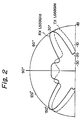
- the directivity of the antenna element 1, such as a helical-type mast antenna is dependent upon the frequency.
- the directivity of the antenna element 1 with respect to the receiving frequency RX is indicated by a solid line in Fig. 2.
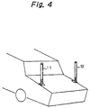
- a transmitting antenna element 11 for the transmitting frequency TX and a receiving antenna element 12 for the receiving frequency RX are provided instead of the single antenna element 1 of Fig. 1.
- the directivities of the transmitting antenna 11 and the receiving antenna 12 are individually adjusted. That is, the directivity ⁇ of the transmitting antenna element 11 can be adjusted at an optimum angle in relation to the satellite SAT with respect to the transmitting frequency TX, and the directivity ⁇ of the receiving antenna element 12 can be adjusted at an optimum angle in relation to the satellite SAT with respect to the receiving frequency RX.
- the antenna elements 11 and 12 are mounted on rear sides of an automobile. In this case, both of the antenna elements 11 and 12 are perpendicular to the ground.
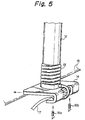
- the bottom end of the antenna element 12 is fixed via a spring 13 to a mounting piece 14.
- the mounting piece 14 has a bent portion to thereby sandwich a rear cover 15 of the automobile, and therefore, the mounting piece 14 is fixed by screws 16a and 16b to the rear cover 15.
- the antenna element 12 restores its location by a restoring force of the spring 13.
- reference numeral 17 designates a cable electrically connected to the antenna element 12. As illustrated in Fig. 6, the cable 17 is connected to a part 2' of the high frequency unit 2 including the bandpass filter 24R and the low noise amplifier 23R, and is further connected via a cable 18 to the radio control unit 3. In this case, the mixer 23 and the synthesizer 21 are provided within the radio control unit 3.
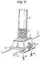
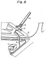
- Fig. 7 which illustrates a modification of Fig. 5
- the part 2' of the high frequency unit 2 is outside of the rear cover 15.
- the cable 17 of Figs. 5 and 6 is not present.
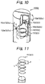
- the antenna element 11 (12) is comprised of a helical conductor element 111 (121), a dielectric cylindrical body 112 (122) for encapsulating the helical conductor element 111 (121), and a dielectric rotatable member 113 (123).
- the bottom end of the helical conductor element 111 (121) is fixed at the dielectric cylindrical body 112 (122), and the top end of the helical conductor element 111 (121) is fixed at the dielectric rotatable member 113 (123).
- the dielectric rotatable member 113 (123) is rotated, the directivity of the antenna element 11 (12) is changed.
- the amount of rotation of the dielectric rotatable member 113 (123), i.e., the directivity of the antenna element 11 (12) is detected by a scale 113a (123a) attached to the dielectric rotatable member 113 (123) with respect to an index 112a (122a) attached to the dielectric cylindrical body 112 (122).
- a groove 112b (122b) is formed in the dielectric cylindrical body 112 (122), and a protrusion 113b (123b) is formed on an inner face of the dielectric rotatable member 113 (123). Therefore, the dielectric rotatable member 113 (123) is rotated, the helical conductor element 111 (121) is twisted to change a pitch P of the helical conductor element 111 (121) and a length L per one helix of the helical conductor element 111 (121) as illustrated in Fig. 11.
- the scale 113a of the dielectric rotatable member 113 corresponds to the directivity ⁇ of the antenna element 11 with respect to the transmitting frequency TX
- the scale 123a of the dielectric rotatable member 123 corresponds to the directivity ⁇ of the antenna element 12 with respect to the receiving frequency RX.
- the directivity ⁇ of the antenna element 11 with respect to the transmitting frequency TX is ⁇ 1
- the directivity ⁇ of the antenna element 12 with respect to the receiving frequency RX is ⁇ 1, the same symbol "1" is attached to the scale.
- the directivity ⁇ of the antenna element 11 with respect to the transmitting frequency TX is ⁇ 2 and the directivity ⁇ of the antenna element 12 with respect to the receiving frequency RX is ⁇ 2, the same symbol "2" is attached to the scale. Therefore, the interval of the scale 113a is different from that of the scale 123a.
- the directric rotatable member 123 is rotated to obtain a maximum gain from the meter 4 which is provided at a suitable location for an operator.
- an optimum directivity of the antenna element 12 with respect to the receiving frequency RX is obtained.
- the scale 123a indicated by the index 122a shows "i”
- the optimum directivity ⁇ of the antenna element 12 with respect to the receiving frequency RX is ⁇ i .
- the operator rotates the dielectric rotatable member 113 until the scale 113a indicated by the index 112a shows "i”.
- the directivity ⁇ of the antenna element 11 with respect to the transmitting frequency TX is also an optimum angle which is, in this case, ⁇ i .
- both of the directivities of the antenna elements 11 and 12 can be optimized.
- optimum directivities of an antenna apparatus to a satellite can be obtained with respect to a transmitting frequency and a receiving frequency which are different from each other. Also, adjustment of the antenna apparatus in relation to the satellite with respect to the transmitting and receiving frequencies is easy.
Landscapes
- Engineering & Computer Science (AREA)
- Remote Sensing (AREA)
- Computer Networks & Wireless Communication (AREA)
- Signal Processing (AREA)
- Variable-Direction Aerials And Aerial Arrays (AREA)
- Details Of Aerials (AREA)
- Support Of Aerials (AREA)
- Radio Relay Systems (AREA)
Applications Claiming Priority (6)
| Application Number | Priority Date | Filing Date | Title |
|---|---|---|---|
| JP161054/93 | 1993-06-30 | ||
| JP18317693 | 1993-06-30 | ||
| JP183176/93 | 1993-06-30 | ||
| JP5183176A JP2500464B2 (ja) | 1993-06-30 | 1993-06-30 | アンテナ装置 |
| JP16105493 | 1993-06-30 | ||
| JP5161054A JPH0779189A (ja) | 1993-06-30 | 1993-06-30 | 移動通信システム |
Publications (2)
| Publication Number | Publication Date |
|---|---|
| EP0632603A1 true EP0632603A1 (fr) | 1995-01-04 |
| EP0632603B1 EP0632603B1 (fr) | 1999-10-06 |
Family
ID=26487324
Family Applications (1)
| Application Number | Title | Priority Date | Filing Date |
|---|---|---|---|
| EP94110127A Expired - Lifetime EP0632603B1 (fr) | 1993-06-30 | 1994-06-29 | Antenne avec des antennes élémentaires pour recevoir ou transmettre des différentes fréquences |
Country Status (5)
| Country | Link |
|---|---|
| US (1) | US5477232A (fr) |
| EP (1) | EP0632603B1 (fr) |
| AU (1) | AU680497B2 (fr) |
| CA (1) | CA2127079C (fr) |
| DE (1) | DE69421009T2 (fr) |
Cited By (5)
| Publication number | Priority date | Publication date | Assignee | Title |
|---|---|---|---|---|
| EP0736926A1 (fr) * | 1995-04-07 | 1996-10-09 | Lk-Products Oy | Antenne de type hélice et procédé de réalisation |
| WO1998028815A1 (fr) * | 1996-12-20 | 1998-07-02 | Ericsson, Inc. | Antenne helicoidale, quadrifilaire, a bande-l |
| WO1998028817A1 (fr) * | 1996-12-20 | 1998-07-02 | Ericsson, Inc. | Procedes et systemes d'antennes helicoïdales quadrifilaires a deux bandes de frequence |
| US5896113A (en) * | 1996-12-20 | 1999-04-20 | Ericsson Inc. | Quadrifilar helix antenna systems and methods for broadband operation in separate transmit and receive frequency bands |
| EP0749214A3 (fr) * | 1995-06-15 | 2000-11-22 | Murata Manufacturing Co., Ltd. | Equipement de radio-communication |
Families Citing this family (6)
| Publication number | Priority date | Publication date | Assignee | Title |
|---|---|---|---|---|
| US5581268A (en) * | 1995-08-03 | 1996-12-03 | Globalstar L.P. | Method and apparatus for increasing antenna efficiency for hand-held mobile satellite communications terminal |
| DE19835878A1 (de) * | 1998-08-07 | 2000-02-17 | Siemens Ag | Antenne mit großer Bandbreite |
| US6448941B1 (en) * | 1999-04-21 | 2002-09-10 | The United States Of America As Represented By The Secretary Of The Navy | Method for secure communications using spiral antennas |
| US6232926B1 (en) * | 1999-11-10 | 2001-05-15 | Xm Satellite Radio Inc. | Dual coupled vehicle glass mount antenna system |
| US6765495B1 (en) | 2000-06-07 | 2004-07-20 | Hrl Laboratories, Llc | Inter vehicle communication system |
| DE10114531A1 (de) * | 2001-03-21 | 2002-10-02 | Funkwerk Dabendorf Gmbh | Schaltungsanordnung zum Kompensieren der Dämpfung in einem Antennenzuleitungskabel für ein Mobilfunkgerät |
Citations (5)
| Publication number | Priority date | Publication date | Assignee | Title |
|---|---|---|---|---|
| US4176356A (en) * | 1977-06-27 | 1979-11-27 | Motorola, Inc. | Directional antenna system including pattern control |
| DE3008684A1 (de) * | 1979-03-12 | 1980-09-25 | Motorola Inc | Verfahren und schaltungsanordnung zur nachrichtenuebertragung in zwei richtungen |
| US4736461A (en) * | 1984-02-29 | 1988-04-05 | Nippon Telegraph & Telephone Public Corporation | Method of transmitting terminating call signals within a restricted duration and a base station and a portable unit for use in the same |
| US5204970A (en) * | 1991-01-31 | 1993-04-20 | Motorola, Inc. | Communication system capable of adjusting transmit power of a subscriber unit |
| EP0540125A1 (fr) * | 1991-10-30 | 1993-05-05 | Valtion Teknillinen Tutkimuskeskus | Système d'antenne pour communication d'un satéllite |
Family Cites Families (7)
| Publication number | Priority date | Publication date | Assignee | Title |
|---|---|---|---|---|
| US4379298A (en) * | 1981-07-20 | 1983-04-05 | Pal International | Tunable citizen band antenna |
| US4916456A (en) * | 1989-05-12 | 1990-04-10 | Don Shyu | Glass-mountable antenna assembly |
| US4992799A (en) * | 1989-09-28 | 1991-02-12 | Motorola, Inc. | Adaptable antenna |
| AT393762B (de) * | 1989-12-18 | 1991-12-10 | Akg Akustische Kino Geraete | Als wendelantenne ausgebildete uhf-sendeund/oder empfangsantenne |
| US5225845A (en) * | 1991-06-21 | 1993-07-06 | Blaese Herbert R | Slip-on portable antenna |
| US5274393A (en) * | 1991-09-23 | 1993-12-28 | Allied-Signal Inc. | Adjustable helical antenna for a VHF radio |
| US5283589A (en) * | 1992-02-05 | 1994-02-01 | Richard Hirschmann Of America, Inc. | Window mountable UHF mobile antenna system |
-
1994
- 1994-06-29 DE DE69421009T patent/DE69421009T2/de not_active Expired - Fee Related
- 1994-06-29 US US08/269,053 patent/US5477232A/en not_active Expired - Fee Related
- 1994-06-29 CA CA002127079A patent/CA2127079C/fr not_active Expired - Fee Related
- 1994-06-29 AU AU66060/94A patent/AU680497B2/en not_active Ceased
- 1994-06-29 EP EP94110127A patent/EP0632603B1/fr not_active Expired - Lifetime
Patent Citations (5)
| Publication number | Priority date | Publication date | Assignee | Title |
|---|---|---|---|---|
| US4176356A (en) * | 1977-06-27 | 1979-11-27 | Motorola, Inc. | Directional antenna system including pattern control |
| DE3008684A1 (de) * | 1979-03-12 | 1980-09-25 | Motorola Inc | Verfahren und schaltungsanordnung zur nachrichtenuebertragung in zwei richtungen |
| US4736461A (en) * | 1984-02-29 | 1988-04-05 | Nippon Telegraph & Telephone Public Corporation | Method of transmitting terminating call signals within a restricted duration and a base station and a portable unit for use in the same |
| US5204970A (en) * | 1991-01-31 | 1993-04-20 | Motorola, Inc. | Communication system capable of adjusting transmit power of a subscriber unit |
| EP0540125A1 (fr) * | 1991-10-30 | 1993-05-05 | Valtion Teknillinen Tutkimuskeskus | Système d'antenne pour communication d'un satéllite |
Cited By (8)
| Publication number | Priority date | Publication date | Assignee | Title |
|---|---|---|---|---|
| EP0736926A1 (fr) * | 1995-04-07 | 1996-10-09 | Lk-Products Oy | Antenne de type hélice et procédé de réalisation |
| US5742259A (en) * | 1995-04-07 | 1998-04-21 | Lk-Products Oy | Resilient antenna structure and a method to manufacture it |
| EP0749214A3 (fr) * | 1995-06-15 | 2000-11-22 | Murata Manufacturing Co., Ltd. | Equipement de radio-communication |
| WO1998028815A1 (fr) * | 1996-12-20 | 1998-07-02 | Ericsson, Inc. | Antenne helicoidale, quadrifilaire, a bande-l |
| WO1998028817A1 (fr) * | 1996-12-20 | 1998-07-02 | Ericsson, Inc. | Procedes et systemes d'antennes helicoïdales quadrifilaires a deux bandes de frequence |
| US5896113A (en) * | 1996-12-20 | 1999-04-20 | Ericsson Inc. | Quadrifilar helix antenna systems and methods for broadband operation in separate transmit and receive frequency bands |
| US5909196A (en) * | 1996-12-20 | 1999-06-01 | Ericsson Inc. | Dual frequency band quadrifilar helix antenna systems and methods |
| US5920292A (en) * | 1996-12-20 | 1999-07-06 | Ericsson Inc. | L-band quadrifilar helix antenna |
Also Published As
| Publication number | Publication date |
|---|---|
| US5477232A (en) | 1995-12-19 |
| DE69421009D1 (de) | 1999-11-11 |
| AU6606094A (en) | 1995-01-12 |
| CA2127079A1 (fr) | 1994-12-31 |
| EP0632603B1 (fr) | 1999-10-06 |
| CA2127079C (fr) | 1998-09-22 |
| DE69421009T2 (de) | 2000-05-25 |
| AU680497B2 (en) | 1997-07-31 |
Similar Documents
| Publication | Publication Date | Title |
|---|---|---|
| US5410749A (en) | Radio communication device having a microstrip antenna with integral receiver systems | |
| US6400931B1 (en) | Card-like wireless communication device | |
| US5477232A (en) | Antenna apparatus having individual transmitting and receiving antenna elements for different frequencies | |
| US5170173A (en) | Antenna coupling apparatus for cordless telephone | |
| EP0214806B1 (fr) | Radio portable | |
| US5539414A (en) | Folded dipole microstrip antenna | |
| KR100334054B1 (ko) | 휴대전화용착탈식플립커버조립체 | |
| US4584709A (en) | Homotropic antenna system for portable radio | |
| JP3275632B2 (ja) | 無線通信装置 | |
| AU718231B2 (en) | Antenna system for dual mode satellite/cellular portable phone | |
| EP0855092B1 (fr) | Procede et systeme de transmission de signaux electromagnetiques | |
| US6459916B1 (en) | Portable radio communication device | |
| CA2156403A1 (fr) | Antenne conique de faible hauteur | |
| US5708445A (en) | Antenna assembly for radio circuit and method therefor | |
| US6456257B1 (en) | System and method for switching between different antenna patterns to satisfy antenna gain requirements over a desired coverage angle | |
| US5945950A (en) | Stacked microstrip antenna for wireless communication | |
| WO1997023016A1 (fr) | Terminal radio portatif ayant des antennes a reception simultanee | |
| US20010041541A1 (en) | Method and antenna arrangement for coupling external antennas to a communication unit | |
| GB2146178A (en) | Method and apparatus for rotation of microwave signal polarization | |
| JP3029119U (ja) | 無線カード | |
| WO2001033666A1 (fr) | Antenne satellite et terrestre bimodale | |
| US6753819B1 (en) | Mobile radio transmitting/receiving device comprising a tunable-antenna | |
| JPH09260931A (ja) | フェーズドアレーアンテナ | |
| US7392073B2 (en) | Terminal apparatus | |
| WO1991001048A1 (fr) | Moyen conferant un effet filtrant a une antenne a rayonnement zenithale reduit |
Legal Events
| Date | Code | Title | Description |
|---|---|---|---|
| PUAI | Public reference made under article 153(3) epc to a published international application that has entered the european phase |
Free format text: ORIGINAL CODE: 0009012 |
|
| 17P | Request for examination filed |
Effective date: 19941031 |
|
| AK | Designated contracting states |
Kind code of ref document: A1 Designated state(s): DE FR GB NL |
|
| 17Q | First examination report despatched |
Effective date: 19980213 |
|
| GRAG | Despatch of communication of intention to grant |
Free format text: ORIGINAL CODE: EPIDOS AGRA |
|
| GRAG | Despatch of communication of intention to grant |
Free format text: ORIGINAL CODE: EPIDOS AGRA |
|
| GRAH | Despatch of communication of intention to grant a patent |
Free format text: ORIGINAL CODE: EPIDOS IGRA |
|
| GRAH | Despatch of communication of intention to grant a patent |
Free format text: ORIGINAL CODE: EPIDOS IGRA |
|
| GRAA | (expected) grant |
Free format text: ORIGINAL CODE: 0009210 |
|
| AK | Designated contracting states |
Kind code of ref document: B1 Designated state(s): DE FR GB NL |
|
| REF | Corresponds to: |
Ref document number: 69421009 Country of ref document: DE Date of ref document: 19991111 |
|
| ET | Fr: translation filed | ||
| PLBE | No opposition filed within time limit |
Free format text: ORIGINAL CODE: 0009261 |
|
| STAA | Information on the status of an ep patent application or granted ep patent |
Free format text: STATUS: NO OPPOSITION FILED WITHIN TIME LIMIT |
|
| 26N | No opposition filed | ||
| REG | Reference to a national code |
Ref country code: GB Ref legal event code: IF02 |
|
| PGFP | Annual fee paid to national office [announced via postgrant information from national office to epo] |
Ref country code: FR Payment date: 20020610 Year of fee payment: 9 |
|
| PGFP | Annual fee paid to national office [announced via postgrant information from national office to epo] |
Ref country code: GB Payment date: 20020626 Year of fee payment: 9 |
|
| PGFP | Annual fee paid to national office [announced via postgrant information from national office to epo] |
Ref country code: NL Payment date: 20020628 Year of fee payment: 9 |
|
| PGFP | Annual fee paid to national office [announced via postgrant information from national office to epo] |
Ref country code: DE Payment date: 20020702 Year of fee payment: 9 |
|
| PG25 | Lapsed in a contracting state [announced via postgrant information from national office to epo] |
Ref country code: GB Free format text: LAPSE BECAUSE OF NON-PAYMENT OF DUE FEES Effective date: 20030629 |
|
| PG25 | Lapsed in a contracting state [announced via postgrant information from national office to epo] |
Ref country code: NL Free format text: LAPSE BECAUSE OF NON-PAYMENT OF DUE FEES Effective date: 20040101 Ref country code: DE Free format text: LAPSE BECAUSE OF NON-PAYMENT OF DUE FEES Effective date: 20040101 |
|
| GBPC | Gb: european patent ceased through non-payment of renewal fee |
Effective date: 20030629 |
|
| PG25 | Lapsed in a contracting state [announced via postgrant information from national office to epo] |
Ref country code: FR Free format text: LAPSE BECAUSE OF NON-PAYMENT OF DUE FEES Effective date: 20040227 |
|
| NLV4 | Nl: lapsed or anulled due to non-payment of the annual fee |
Effective date: 20040101 |
|
| REG | Reference to a national code |
Ref country code: FR Ref legal event code: ST |