EP0632603B1 - Antennenverbindung mit individuellen Sende- und Empfangsantennenelementen für unterschiedliche Frequenzen - Google Patents
Antennenverbindung mit individuellen Sende- und Empfangsantennenelementen für unterschiedliche Frequenzen Download PDFInfo
- Publication number
- EP0632603B1 EP0632603B1 EP94110127A EP94110127A EP0632603B1 EP 0632603 B1 EP0632603 B1 EP 0632603B1 EP 94110127 A EP94110127 A EP 94110127A EP 94110127 A EP94110127 A EP 94110127A EP 0632603 B1 EP0632603 B1 EP 0632603B1
- Authority
- EP
- European Patent Office
- Prior art keywords
- antenna element
- receiving
- transmitting
- frequency
- beam direction
- Prior art date
- Legal status (The legal status is an assumption and is not a legal conclusion. Google has not performed a legal analysis and makes no representation as to the accuracy of the status listed.)
- Expired - Lifetime
Links
- 239000004020 conductor Substances 0.000 claims description 14
- 238000004891 communication Methods 0.000 claims description 10
- 238000010586 diagram Methods 0.000 description 4
- 238000012986 modification Methods 0.000 description 3
- 230000004048 modification Effects 0.000 description 3
- 230000001419 dependent effect Effects 0.000 description 2
- 238000012544 monitoring process Methods 0.000 description 2
- 238000011161 development Methods 0.000 description 1
- 230000018109 developmental process Effects 0.000 description 1
- 230000005670 electromagnetic radiation Effects 0.000 description 1
- 238000000034 method Methods 0.000 description 1
Images



Classifications
-
- H—ELECTRICITY
- H01—ELECTRIC ELEMENTS
- H01Q—ANTENNAS, i.e. RADIO AERIALS
- H01Q1/00—Details of, or arrangements associated with, antennas
- H01Q1/27—Adaptation for use in or on movable bodies
- H01Q1/32—Adaptation for use in or on road or rail vehicles
- H01Q1/325—Adaptation for use in or on road or rail vehicles characterised by the location of the antenna on the vehicle
- H01Q1/3275—Adaptation for use in or on road or rail vehicles characterised by the location of the antenna on the vehicle mounted on a horizontal surface of the vehicle, e.g. on roof, hood, trunk
-
- H—ELECTRICITY
- H01—ELECTRIC ELEMENTS
- H01Q—ANTENNAS, i.e. RADIO AERIALS
- H01Q11/00—Electrically-long antennas having dimensions more than twice the shortest operating wavelength and consisting of conductive active radiating elements
- H01Q11/02—Non-resonant antennas, e.g. travelling-wave antenna
- H01Q11/08—Helical antennas
-
- H—ELECTRICITY
- H04—ELECTRIC COMMUNICATION TECHNIQUE
- H04B—TRANSMISSION
- H04B1/00—Details of transmission systems, not covered by a single one of groups H04B3/00 - H04B13/00; Details of transmission systems not characterised by the medium used for transmission
- H04B1/38—Transceivers, i.e. devices in which transmitter and receiver form a structural unit and in which at least one part is used for functions of transmitting and receiving
Definitions
- a satellite antenna system comprising a single radiator unit for receiving and transmitting electromagnetic radiation is described in EP-A-540 125.
- the elevation angle of the radiator unit is variable by a support such that the radiator unit can be directed to a satellite.
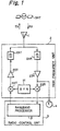
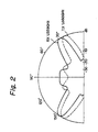
- optimum beam directions of an antenna apparatus to a satellite can be obtained with respect to a transmitting frequency and a receiving frequency which are different from each other. Also, adjustment of the antenna apparatus in relation to the satellite with respect to the transmitting and receiving frequencies is easy.
Landscapes
- Engineering & Computer Science (AREA)
- Remote Sensing (AREA)
- Computer Networks & Wireless Communication (AREA)
- Signal Processing (AREA)
- Variable-Direction Aerials And Aerial Arrays (AREA)
- Details Of Aerials (AREA)
- Support Of Aerials (AREA)
- Radio Relay Systems (AREA)
Claims (7)
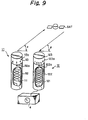
- Antennenvorrichtung, die an einer Mobilstation für die Kommunikation mit einem Satelliten (SAT) vorgesehen ist, mit:einem Sendeantennenelement (11) zum Senden eines ersten Signals mit einer Sendefrequenz (TX) an den Satelliten und einem Empfangsantennenelement (12) zum Empfang eines zweiten Signals mit einer Empfangsfrequenz (RX) von dem Satelliten,wobei sich die Empfangsfrequenz von der Sendefrequenz unterscheidet,einem ersten Einstellmittel zum Einstellen einer Strahlrichtung (α) des Sendeantennenelementes für eine gegebene Sendefrequenz undeinem zweiten Einstellmittel zum Einstellen einer Strahlrichtung (β) des Empfangsantennenelements für eine gegebene Empfangsfrequenz,wobei das erste Einstellmittel eine erste Skala (113a) aufweist, die die Strahlrichtung des Sendenantennenelementes für eine gegebene Sendefrequenz zeigt, und das zweite Einstellmittel eine zweite Skala (123a) aufweist, die die Strahlrichtung des Empfangsantennenelementes für eine gegebene Empfangsfrequenz zeigt.
- Vorrichtung nach Anspruch 1,wobei sowohl das Sendeantennenelement als auch das Empfangsantennenelement ein Helixantennenelement aufweist.
- Antennenvorrichtung, die an einer Mobilstation für die Kommunikation mit einem Satelliten (SAT) vorgesehen ist, miteinem Sendeantennenelement (11) zum Übermitteln eines ersten Signals mit einer Sendefrequenz (TX) an den Satelliten undeinem Empfangsantennenelement (12) zum Empfangen eines zweiten Signals mit einer Empfangsfrequenz (RX) von dem Satelliten,wobei sich die Empfangsfrequenz von der Sendefrequenz unterscheidet und sowohl das Sendeantennenelement als auch das Empfangsantennenelement ein Helixantennenelement aufweist mit:einem wendelartigen Leiterelement (111, 121),einem dielektrischen zylindrischen Körper (112, 122) zum Einkapseln des wendelförmigen Leiterelementes, wobei ein Ende des wendelförmigen Leiterelementes an dem dielektrischen zylindrischen Körper befestigt ist, undeinem dielektrischen drehbaren Element (113, 123), das drehbar in dem dielektrischen zylindrischen Körper montiert ist, wobei das andere Ende des wendelförmigen Leiterelementes an dem dielektrischen drehbaren Element fixiert ist,wobei eine Drehung des dielektrischen drehbaren Elementes den Wendelversatz des wendelförmigen Leiterelementes ändert, um die Strahlrichtung des wendelförmigen Antennenelementes zu ändern.
- Vorrichtung nach Anspruch 3,wobei eine erste Skala (113a), die die Strahlrichtung (α) des Sendeantennenelementes für eine gegebene Sendefrequenz anzeigt, an dem dielektrischen zylindrischen Körper oder dem dielektrischen drehbaren Element des Sendeantennenelementes befestigt ist und ein erster Index (112a) an dem anderen Element, dem dielektrischen zylindrischen Körper oder dem dielektrischen drehbaren Element, des Sendeantennenelementes befestigt ist, undwobei eine zweite Skala (123a), die eine Strahlrichtung (a) des Empfangsantennenelementes für eine gegegeben Empfangsfrequenz zeigt, an dem dielektrischen zylindrischen Körper oder dem dielektrischen drehbaren Element des Empfangsantennenelementes befestigt ist, und wobei ein zweiter Index (122a) mit dem anderen Element, dem dielektrischen zylindrischen Körper oder dem dielektrischen drehbaren Element, des Empfangsantennenelementes verbunden ist.
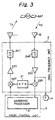
- Vorrichtung nach Anspruch 1,mit weiterhin:einer ersten Hochfrequenzeinheit (21, 22T, 23T, 24T), die mit dem Sendeantennenelement verbunden ist,einer zweiten Hochfrequenzeinheit (21, 22R, 23R, 24R), die mit dem Empfangsantennenelement verbunden ist,einer Funksteuereinheit (3), die mit der ersten und der zweiten Hochfrequenzeinheit verbunden ist, undeiner Meßeinrichtung (4), die mit der zweiten Hochfrequenzeinheit verbunden ist, um einen Empfangszustand des Empfangsantennenelementes anzuzeigen.
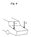
- Vorrichtung nach Anspruch 5,wobei die Mobilstation auf einem Automobil montiert ist,das Sendeantennenelement, das Empfangsantennenelement und die Meßeinrichtung außerhalb des Automobils vorgesehen sind,wobei die erste und die zweite Hochfrequenzeinheit und die Funksteuereinheit innerhalb des Automobils vorgesehen sind.
- Vorrichtung nach Anspruch 5,wobei die Mobilstation auf einem Automobil montiert ist,wobei das Sendeantennenelement, das Empfangsantennenelement und die erste und die zweite Hochfrequenzeinheit außerhalb des Automobils vorgesehen sind, und die Funksteuereinheit innerhalb des Automobils vorgesehen ist.
Applications Claiming Priority (6)
| Application Number | Priority Date | Filing Date | Title |
|---|---|---|---|
| JP161054/93 | 1993-06-30 | ||
| JP18317693 | 1993-06-30 | ||
| JP183176/93 | 1993-06-30 | ||
| JP5183176A JP2500464B2 (ja) | 1993-06-30 | 1993-06-30 | アンテナ装置 |
| JP16105493 | 1993-06-30 | ||
| JP5161054A JPH0779189A (ja) | 1993-06-30 | 1993-06-30 | 移動通信システム |
Publications (2)
| Publication Number | Publication Date |
|---|---|
| EP0632603A1 EP0632603A1 (de) | 1995-01-04 |
| EP0632603B1 true EP0632603B1 (de) | 1999-10-06 |
Family
ID=26487324
Family Applications (1)
| Application Number | Title | Priority Date | Filing Date |
|---|---|---|---|
| EP94110127A Expired - Lifetime EP0632603B1 (de) | 1993-06-30 | 1994-06-29 | Antennenverbindung mit individuellen Sende- und Empfangsantennenelementen für unterschiedliche Frequenzen |
Country Status (5)
| Country | Link |
|---|---|
| US (1) | US5477232A (de) |
| EP (1) | EP0632603B1 (de) |
| AU (1) | AU680497B2 (de) |
| CA (1) | CA2127079C (de) |
| DE (1) | DE69421009T2 (de) |
Families Citing this family (11)
| Publication number | Priority date | Publication date | Assignee | Title |
|---|---|---|---|---|
| FI109493B (fi) * | 1995-04-07 | 2002-08-15 | Filtronic Lk Oy | Joustava antennirakenne ja menetelmä sen valmistamiseksi |
| JP3275632B2 (ja) * | 1995-06-15 | 2002-04-15 | 株式会社村田製作所 | 無線通信装置 |
| US5581268A (en) * | 1995-08-03 | 1996-12-03 | Globalstar L.P. | Method and apparatus for increasing antenna efficiency for hand-held mobile satellite communications terminal |
| US5920292A (en) * | 1996-12-20 | 1999-07-06 | Ericsson Inc. | L-band quadrifilar helix antenna |
| US5896113A (en) * | 1996-12-20 | 1999-04-20 | Ericsson Inc. | Quadrifilar helix antenna systems and methods for broadband operation in separate transmit and receive frequency bands |
| US5909196A (en) * | 1996-12-20 | 1999-06-01 | Ericsson Inc. | Dual frequency band quadrifilar helix antenna systems and methods |
| DE19835878A1 (de) * | 1998-08-07 | 2000-02-17 | Siemens Ag | Antenne mit großer Bandbreite |
| US6448941B1 (en) * | 1999-04-21 | 2002-09-10 | The United States Of America As Represented By The Secretary Of The Navy | Method for secure communications using spiral antennas |
| US6232926B1 (en) * | 1999-11-10 | 2001-05-15 | Xm Satellite Radio Inc. | Dual coupled vehicle glass mount antenna system |
| US6765495B1 (en) | 2000-06-07 | 2004-07-20 | Hrl Laboratories, Llc | Inter vehicle communication system |
| DE10114531A1 (de) * | 2001-03-21 | 2002-10-02 | Funkwerk Dabendorf Gmbh | Schaltungsanordnung zum Kompensieren der Dämpfung in einem Antennenzuleitungskabel für ein Mobilfunkgerät |
Family Cites Families (12)
| Publication number | Priority date | Publication date | Assignee | Title |
|---|---|---|---|---|
| US4176356A (en) * | 1977-06-27 | 1979-11-27 | Motorola, Inc. | Directional antenna system including pattern control |
| US4229741A (en) * | 1979-03-12 | 1980-10-21 | Motorola, Inc. | Two-way communications system and method of synchronizing |
| US4379298A (en) * | 1981-07-20 | 1983-04-05 | Pal International | Tunable citizen band antenna |
| JPS60182825A (ja) * | 1984-02-29 | 1985-09-18 | Nec Corp | 無線電話方式 |
| US4916456A (en) * | 1989-05-12 | 1990-04-10 | Don Shyu | Glass-mountable antenna assembly |
| US4992799A (en) * | 1989-09-28 | 1991-02-12 | Motorola, Inc. | Adaptable antenna |
| AT393762B (de) * | 1989-12-18 | 1991-12-10 | Akg Akustische Kino Geraete | Als wendelantenne ausgebildete uhf-sendeund/oder empfangsantenne |
| US5204970A (en) * | 1991-01-31 | 1993-04-20 | Motorola, Inc. | Communication system capable of adjusting transmit power of a subscriber unit |
| US5225845A (en) * | 1991-06-21 | 1993-07-06 | Blaese Herbert R | Slip-on portable antenna |
| US5274393A (en) * | 1991-09-23 | 1993-12-28 | Allied-Signal Inc. | Adjustable helical antenna for a VHF radio |
| FI90927C (fi) * | 1991-10-30 | 1994-04-11 | Valtion Teknillinen | Satelliittiantennijärjestely |
| US5283589A (en) * | 1992-02-05 | 1994-02-01 | Richard Hirschmann Of America, Inc. | Window mountable UHF mobile antenna system |
-
1994
- 1994-06-29 DE DE69421009T patent/DE69421009T2/de not_active Expired - Fee Related
- 1994-06-29 US US08/269,053 patent/US5477232A/en not_active Expired - Fee Related
- 1994-06-29 CA CA002127079A patent/CA2127079C/en not_active Expired - Fee Related
- 1994-06-29 AU AU66060/94A patent/AU680497B2/en not_active Ceased
- 1994-06-29 EP EP94110127A patent/EP0632603B1/de not_active Expired - Lifetime
Also Published As
| Publication number | Publication date |
|---|---|
| US5477232A (en) | 1995-12-19 |
| DE69421009D1 (de) | 1999-11-11 |
| AU6606094A (en) | 1995-01-12 |
| CA2127079A1 (en) | 1994-12-31 |
| EP0632603A1 (de) | 1995-01-04 |
| CA2127079C (en) | 1998-09-22 |
| DE69421009T2 (de) | 2000-05-25 |
| AU680497B2 (en) | 1997-07-31 |
Similar Documents
| Publication | Publication Date | Title |
|---|---|---|
| US5539414A (en) | Folded dipole microstrip antenna | |
| EP0632603B1 (de) | Antennenverbindung mit individuellen Sende- und Empfangsantennenelementen für unterschiedliche Frequenzen | |
| EP1374338B1 (de) | Kompakte mehrbandantenne | |
| AU718231B2 (en) | Antenna system for dual mode satellite/cellular portable phone | |
| CA2330990C (en) | An improved phases array terminal for equitorial satellite constellations | |
| EP0855092B1 (de) | Verfahren und system zur übertragung elektromagnetischer signale | |
| US6459916B1 (en) | Portable radio communication device | |
| CA2156403A1 (en) | Short conical antenna | |
| WO2000001028A1 (en) | Dual embedded antenna for an rf data communications device | |
| US6281850B1 (en) | Broadband multiple element antenna system | |
| US6456257B1 (en) | System and method for switching between different antenna patterns to satisfy antenna gain requirements over a desired coverage angle | |
| US5274388A (en) | Antenna device | |
| JP2000077924A (ja) | 送受信器 | |
| EP0431764B1 (de) | Antenne mit gekrümmten Dipolelementen | |
| US7843392B2 (en) | Dual frequency antenna system | |
| JP3029119U (ja) | 無線カード | |
| WO2001033666A1 (en) | Dual-mode satellite and terrestrial antenna | |
| US5463358A (en) | Multiple channel microwave rotary polarizer | |
| US6753819B1 (en) | Mobile radio transmitting/receiving device comprising a tunable-antenna | |
| US5072232A (en) | End-fed rod antenna | |
| CA2217730A1 (en) | Planar array antenna | |
| EP0481986B1 (de) | Filterwirkung aufweisende mittel durch antennendiversity | |
| JPH09260931A (ja) | フェーズドアレーアンテナ | |
| JPH09284831A (ja) | 携帯無線機 | |
| Hase et al. | Slot array antenna system for COMETS advanced mobile satcom experiments |
Legal Events
| Date | Code | Title | Description |
|---|---|---|---|
| PUAI | Public reference made under article 153(3) epc to a published international application that has entered the european phase |
Free format text: ORIGINAL CODE: 0009012 |
|
| 17P | Request for examination filed |
Effective date: 19941031 |
|
| AK | Designated contracting states |
Kind code of ref document: A1 Designated state(s): DE FR GB NL |
|
| 17Q | First examination report despatched |
Effective date: 19980213 |
|
| GRAG | Despatch of communication of intention to grant |
Free format text: ORIGINAL CODE: EPIDOS AGRA |
|
| GRAG | Despatch of communication of intention to grant |
Free format text: ORIGINAL CODE: EPIDOS AGRA |
|
| GRAH | Despatch of communication of intention to grant a patent |
Free format text: ORIGINAL CODE: EPIDOS IGRA |
|
| GRAH | Despatch of communication of intention to grant a patent |
Free format text: ORIGINAL CODE: EPIDOS IGRA |
|
| GRAA | (expected) grant |
Free format text: ORIGINAL CODE: 0009210 |
|
| AK | Designated contracting states |
Kind code of ref document: B1 Designated state(s): DE FR GB NL |
|
| REF | Corresponds to: |
Ref document number: 69421009 Country of ref document: DE Date of ref document: 19991111 |
|
| ET | Fr: translation filed | ||
| PLBE | No opposition filed within time limit |
Free format text: ORIGINAL CODE: 0009261 |
|
| STAA | Information on the status of an ep patent application or granted ep patent |
Free format text: STATUS: NO OPPOSITION FILED WITHIN TIME LIMIT |
|
| 26N | No opposition filed | ||
| REG | Reference to a national code |
Ref country code: GB Ref legal event code: IF02 |
|
| PGFP | Annual fee paid to national office [announced via postgrant information from national office to epo] |
Ref country code: FR Payment date: 20020610 Year of fee payment: 9 |
|
| PGFP | Annual fee paid to national office [announced via postgrant information from national office to epo] |
Ref country code: GB Payment date: 20020626 Year of fee payment: 9 |
|
| PGFP | Annual fee paid to national office [announced via postgrant information from national office to epo] |
Ref country code: NL Payment date: 20020628 Year of fee payment: 9 |
|
| PGFP | Annual fee paid to national office [announced via postgrant information from national office to epo] |
Ref country code: DE Payment date: 20020702 Year of fee payment: 9 |
|
| PG25 | Lapsed in a contracting state [announced via postgrant information from national office to epo] |
Ref country code: GB Free format text: LAPSE BECAUSE OF NON-PAYMENT OF DUE FEES Effective date: 20030629 |
|
| PG25 | Lapsed in a contracting state [announced via postgrant information from national office to epo] |
Ref country code: NL Free format text: LAPSE BECAUSE OF NON-PAYMENT OF DUE FEES Effective date: 20040101 Ref country code: DE Free format text: LAPSE BECAUSE OF NON-PAYMENT OF DUE FEES Effective date: 20040101 |
|
| GBPC | Gb: european patent ceased through non-payment of renewal fee |
Effective date: 20030629 |
|
| PG25 | Lapsed in a contracting state [announced via postgrant information from national office to epo] |
Ref country code: FR Free format text: LAPSE BECAUSE OF NON-PAYMENT OF DUE FEES Effective date: 20040227 |
|
| NLV4 | Nl: lapsed or anulled due to non-payment of the annual fee |
Effective date: 20040101 |
|
| REG | Reference to a national code |
Ref country code: FR Ref legal event code: ST |