EP0633012A1 - Injecteur pour baignoire - Google Patents
Injecteur pour baignoire Download PDFInfo
- Publication number
- EP0633012A1 EP0633012A1 EP94108431A EP94108431A EP0633012A1 EP 0633012 A1 EP0633012 A1 EP 0633012A1 EP 94108431 A EP94108431 A EP 94108431A EP 94108431 A EP94108431 A EP 94108431A EP 0633012 A1 EP0633012 A1 EP 0633012A1
- Authority
- EP
- European Patent Office
- Prior art keywords
- insert element
- nozzle
- nozzle body
- tub
- nozzle according
- Prior art date
- Legal status (The legal status is an assumption and is not a legal conclusion. Google has not performed a legal analysis and makes no representation as to the accuracy of the status listed.)
- Granted
Links
Images
Classifications
-
- A—HUMAN NECESSITIES
- A61—MEDICAL OR VETERINARY SCIENCE; HYGIENE
- A61H—PHYSICAL THERAPY APPARATUS, e.g. DEVICES FOR LOCATING OR STIMULATING REFLEX POINTS IN THE BODY; ARTIFICIAL RESPIRATION; MASSAGE; BATHING DEVICES FOR SPECIAL THERAPEUTIC OR HYGIENIC PURPOSES OR SPECIFIC PARTS OF THE BODY
- A61H33/00—Bathing devices for special therapeutic or hygienic purposes
- A61H33/60—Components specifically designed for the therapeutic baths of groups A61H33/00
- A61H33/601—Inlet to the bath
- A61H33/6021—Nozzles
- A61H33/6063—Specifically adapted for fitting in bathtub walls
-
- A—HUMAN NECESSITIES
- A61—MEDICAL OR VETERINARY SCIENCE; HYGIENE
- A61H—PHYSICAL THERAPY APPARATUS, e.g. DEVICES FOR LOCATING OR STIMULATING REFLEX POINTS IN THE BODY; ARTIFICIAL RESPIRATION; MASSAGE; BATHING DEVICES FOR SPECIAL THERAPEUTIC OR HYGIENIC PURPOSES OR SPECIFIC PARTS OF THE BODY
- A61H33/00—Bathing devices for special therapeutic or hygienic purposes
- A61H33/60—Components specifically designed for the therapeutic baths of groups A61H33/00
- A61H33/601—Inlet to the bath
- A61H33/6021—Nozzles
- A61H33/6052—Having flow regulating means
-
- A—HUMAN NECESSITIES
- A61—MEDICAL OR VETERINARY SCIENCE; HYGIENE
- A61H—PHYSICAL THERAPY APPARATUS, e.g. DEVICES FOR LOCATING OR STIMULATING REFLEX POINTS IN THE BODY; ARTIFICIAL RESPIRATION; MASSAGE; BATHING DEVICES FOR SPECIAL THERAPEUTIC OR HYGIENIC PURPOSES OR SPECIFIC PARTS OF THE BODY
- A61H33/00—Bathing devices for special therapeutic or hygienic purposes
- A61H33/02—Bathing devices for use with gas-containing liquid, or liquid in which gas is led or generated, e.g. carbon dioxide baths
- A61H33/026—Gas nozzles specially adapted therefor
Definitions
- the invention relates to a nozzle for a tub, which is preferably designed as a whirlpool tub, according to the features specified in the preamble of claim 1.
- a nozzle for supplying air or water into a tub is known.
- a nozzle is arranged in particular in the bottom of the tub and contains a nozzle body which can be connected to the tub bottom and which has a flange at its upper end and is otherwise essentially cylindrical and has an external thread.
- the nozzle body can be inserted into a bore in the trough base, the flange mentioned lying expediently resting on the inner surface of the trough base via a seal. If the nozzle body is inserted into the mentioned bore of the tub or the tub bottom, the aforementioned external thread projects on the underside out of the tub floor and there is attached using a union nut.
- the nozzle body has a connection for air, which can thus be pumped from a connected line system into the interior of the tub.
- an insert element which is inserted into the nozzle body from the inside of the trough and is screwed into the nozzle body via a threaded connection.
- the insert element is essentially cylindrical and has an external thread for the thread connection mentioned in its outer surface.
- this insert element has continuous longitudinal grooves on its outer surface over its entire length. If air is supplied through the pipe system, it flows through the longitudinal grooves mentioned into the interior of the tub. The inflow of air is predetermined by the cross section of the mentioned longitudinal grooves and a change or regulation of the amount of air is not readily possible.
- a bath tub nozzle is known from DE-A-3 939 665, the cylindrical nozzle body of which in turn has a flange which, when installed, rests on the inner surface of the tub floor.
- the nozzle body is fastened to the tub bottom by means of a seal and a nut screwed onto an external thread of the nozzle body in the area of the underside of the tub bottom.
- the inside of the nozzle body has an axially continuous bore through which air can be pumped into the tub from the connected line system.
- the nozzle head which can be inserted into the nozzle body from the inside of the tub, has an annular rim on the inside, which overlaps the flange of the nozzle body.
- the flange and also the nozzle head with said edge each have a corresponding wall thickness for reasons of strength and stability, with the result that the surface of the nozzle head protrudes to a considerable extent over the inner surface of the tub.
- nozzle bodies regularly protrude about 5-8 mm above the inner surface of the tub floor and are therefore an obstacle for a user.
- a sanitary air jet nozzle is known, the insert element of which is also essentially cylindrical, but parts of the thread are removed over the entire length. Between the worn flat areas and the internal thread of the nozzle body there is a comparatively narrow gap parallel to the longitudinal axis through which the air supplied to the nozzle body can flow into the interior of the tub.
- the gap width and thus the passage cross section is comparatively small and, moreover, cannot be changed.
- EP-A-270 858 discloses an outlet nozzle for the outlet valve of a whirlpool bath with a channel for the water supply and a channel for the air supply. Between an outer plate-shaped distribution body and an inner distribution body, which are connected to one another by means of ribs, there is a circular outlet channel, the outlet channel being divided into individual radial outlet channels in the interior of the said distribution body. The distance between the two distribution bodies is predefined and it is not possible to change the amount of water flowing through the outlet channel in the radial direction. Furthermore, between the inner distribution body and the trough bottom there is a gap which is connected to the air supply duct and whose width cannot be changed.
- the object of the invention is to further develop the nozzle of the type mentioned with little effort in such a way that the inflow of air or water is reliably made possible, the inflow quantity being changeable without difficulty and the construction volume being small.
- Flow losses, pressure drop due to deflection or the like should remain as small as possible so that a good inflow into the tub interior is ensured without a high pressure output of the pump of the air control system or the like being required for this.
- the nozzle should have compact dimensions and require little production and assembly effort.
- the cleaning of the nozzle should be able to be carried out easily and without special tools or aids.
- the nozzle according to the invention is characterized by a simple and reliable construction and can be manufactured without any special manufacturing effort become.
- the nozzle is only very small in the area of the inner tub surface.
- the nozzle body has an inner surface that opens conically to the inside of the tub.
- the insert element also has a conical outer surface, but the opening angle is larger by a predetermined amount than the opening angle of the inner surface of the nozzle body.
- the conical inner surface of the nozzle body on the one hand and the conical outer surface of the insert element on the other hand are matched in such a way that the width of the gap through which the medium flows out can be predetermined in accordance with the screw-in depth of the insert element.
- the conical outer surface of the insert element ends in the area of an annular groove.
- the insert element Adjoining the annular groove to the lower end of the insert element, the insert element has an outer diameter that is larger than the bottom of the annular groove, the external thread being provided there for screwing into the nozzle body. Finally, the insert element has an axial blind bore, which begins at its lower end and into which essentially radially aligned bores emanating from said annular groove open. In the area of the annular groove, a number of such radially directed bores are provided, between which there are only comparatively small webs. The air flowing in from below can thus flow from the blind bore through the radial bores mentioned into the annular gap and finally into the interior of the tub without substantial deflections.
- the insert element screwed into the nozzle body can, if necessary, be easily removed from the nozzle body for the purpose of cleaning. After unscrewing the insert element, the interior of the nozzle body is easily accessible and the insert element can then also be cleaned without particular difficulty. No complex machines or tools are required to produce the nozzle, and overall only a few processing steps are required to produce the nozzle body on the one hand and the insert element on the other.
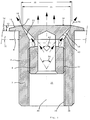
- the nozzle body 1 shows a longitudinal section through the nozzle, which contains a nozzle body 2 and an insert element 4.
- the nozzle body has an external thread 6 on its substantially cylindrical outer surface and a flange 8 at its upper end.
- the nozzle body 2 can be placed in a known manner in a recess or bore in a trough bottom 10, which here; is indicated by dash-dotted lines.
- a seal not shown
- a nut screwed onto the external thread 6 from the underside of the tub bottom the nozzle body 2 is fixed in a known manner on the tub bottom.
- the floor nozzle according to the invention only projects at a height 12, which essentially corresponds to the height of the flange, over the inner surface 14 of the tub.
- the surface 16 of the flange 8 is expediently conical in such a way that the height at the outer edge is lower than at the radially inner edge 18 of the outlet opening 20. From the edge 18 mentioned, an inner surface 22 of the outlet opening runs conically inwards, specifically with a first opening angle 24.
- the inside of the nozzle body contains a through hole 26 through which the medium to be conveyed into the trough, in particular air or water, can be fed.
- suitable connecting means for connecting the floor nozzle to a line system for the medium mentioned can be provided.
- the through hole 26 contains an internal thread 30 into which the insert element 4 can be screwed with its external thread 32.
- the first opening angle 24 is expediently in the range between 40 and 100 degrees, preferably between 60 and 80 degrees.
- the conical inner surface 22 extends from the internal thread 30 to the edge 18.
- the insert element 2 has at its upper end an essentially flat surface 34 lying inside the tub.
- the insert element 4 has an outer diameter 36 which is at most the same or a predetermined amount smaller than the inner diameter 38 of the Nozzle body 2 or the conical inner surface 22 on said edge 18. It is also of decisive importance that the insert element has at its upper end an outer surface 40 which is also conical with a second opening angle 42. This second opening angle 42 is larger than the first opening angle 24 of the nozzle body 2.
- the two opening angles 24 and 42 are coordinated with one another in such a way that the gap width of the outlet opening 20 can be predetermined in accordance with the screwing depth of the insert element 4 into the nozzle body 2.
- the second opening angle 42 is of the order of magnitude between 60 and 120, preferably between 80 and 100 degrees.
- the second opening angle 42 of the insert element 4 is essentially 90 degrees
- the first opening angle of the nozzle body 2 is essentially 70 degrees. So there is an angle difference of approx. 20 degrees.
- an annular gap 44 which tapers towards the edge 18 or the outlet opening 20, which results in particularly favorable flow conditions and the medium supplied under pressure in accordance with the Arrows 46 flow from the annular outlet opening 20 into the tub interior.
- the gap width of the outlet opening 20 is variable and for this purpose only the insert element 4 has to be screwed more or less deeply into the nozzle body 2.
- the inner surface 22 and the opposite outer surface 40 are designed as conical surfaces.
- the surfaces mentioned are, for example, spherically curved. It is decisive in all embodiments that the gap width of the outlet opening 20 can be changed by moving the insert element 4 with respect to the nozzle body 2. If the insert element 4 is completely screwed into the nozzle body 2 in such a way that the gap width of the outlet opening 20 approaches zero, the nozzle is practically closed and the medium supplied is prevented from flowing out.
- the insert element 4 in relation to the position shown, is screwed up a little further out of the nozzle body 2 in the direction of the longitudinal axis 48, the gap width of the outlet opening 20 becomes larger and the medium can flow out more easily.
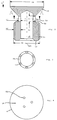
- FIG. 2 shows an axial section of the insert element 4, which has a blind bore 50 aligned with the longitudinal axis 48 in the interior.
- the blind bore begins at the lower end 52 of the insert element and ends at a predetermined distance in front of the surface 34.
- a recess or an annular groove 54 is provided essentially coaxially with the longitudinal axis 48, which, viewed in the axial direction, between the conical outer surface 40 and the external thread 32 is arranged.
- the connection between the blind bore 54 and the outer region of the insert element 4 is established by means of recesses, which are designed in particular as radial bores 56.
- the preferably conical outer surface 40 ends in the annular groove 54.
- the outer diameter 36 in the area of the surface 34 is significantly larger than the outer diameter 58 of the external thread 32.
- the medium is made of the blind bore 50 can flow substantially unhindered radially outwards in the direction of the outlet opening 20. Significant flow deflections, eddies or the like, which could lead to a noticeable drop in pressure, are avoided.
- the depth of the annular groove 54, measured from the outer diameter 58, is expediently greater than the wall thickness 60 of the insert element 4 in the area of the external thread 58.
- the insert element 4 in the area of the annular groove 54 or the area there existing radial recesses has a much smaller thickness 62 than the aforementioned wall thickness 60.
- the thickness 62 is at most only half as large as the wall thickness 60. This dimensioning ensures that the inner nozzle in the region of the recesses or radial bores 56 has a favorable flow pattern for the medium, which is largely unhindered from the blind bore 50 to the outlet opening can flow.
- the diameter of the bores 56 is essentially the same size as the axial length 64 of the bottom of the annular groove 54.
- FIG. 3 shows a section along line A according to FIG. 2, the part of the insert element with the external thread lying behind the drawing plane not being shown for the sake of simplicity.
- FIG. 4 shows the insert element 4 in the direction of view B according to FIG. 2 on the flat surface 34.
- Three additional bores 68 are provided, which form a direct connection from the blind hole in the interior of the insert element 4 into the interior of the tub. These additional bores ensure an improved regulation of the amount of the medium supplied, in particular air.
Landscapes
- Health & Medical Sciences (AREA)
- Public Health (AREA)
- Life Sciences & Earth Sciences (AREA)
- Pain & Pain Management (AREA)
- Physical Education & Sports Medicine (AREA)
- Rehabilitation Therapy (AREA)
- Epidemiology (AREA)
- Animal Behavior & Ethology (AREA)
- General Health & Medical Sciences (AREA)
- Veterinary Medicine (AREA)
- Nozzles (AREA)
- Looms (AREA)
- Fuel-Injection Apparatus (AREA)
- Coating Apparatus (AREA)
- Percussion Or Vibration Massage (AREA)
Applications Claiming Priority (2)
| Application Number | Priority Date | Filing Date | Title |
|---|---|---|---|
| DE4322812 | 1993-07-08 | ||
| DE4322812A DE4322812C1 (de) | 1993-07-08 | 1993-07-08 | Düse für eine Wanne |
Publications (3)
| Publication Number | Publication Date |
|---|---|
| EP0633012A1 true EP0633012A1 (fr) | 1995-01-11 |
| EP0633012B1 EP0633012B1 (fr) | 1999-12-01 |
| EP0633012B2 EP0633012B2 (fr) | 2003-07-09 |
Family
ID=6492294
Family Applications (1)
| Application Number | Title | Priority Date | Filing Date |
|---|---|---|---|
| EP94108431A Expired - Lifetime EP0633012B2 (fr) | 1993-07-08 | 1994-06-01 | Injecteur pour baignoire |
Country Status (4)
| Country | Link |
|---|---|
| EP (1) | EP0633012B2 (fr) |
| AT (1) | ATE187060T1 (fr) |
| DE (2) | DE4322812C1 (fr) |
| ES (1) | ES2140478T3 (fr) |
Families Citing this family (1)
| Publication number | Priority date | Publication date | Assignee | Title |
|---|---|---|---|---|
| AT408518B (de) * | 2000-03-28 | 2001-12-27 | Koller Rudolf | Massagedüse |
Citations (5)
| Publication number | Priority date | Publication date | Assignee | Title |
|---|---|---|---|---|
| GB311161A (en) * | 1928-08-31 | 1929-05-09 | George Edward Kevin Blythe | Improvements in or relating to liquid spraying nozzles |
| US2447123A (en) * | 1944-08-09 | 1948-08-17 | Jones Harry Sloper | Therapeutic device |
| EP0168823A2 (fr) * | 1984-07-17 | 1986-01-22 | Jacuzzi Europe Spa | Buse d'hydromassage |
| DE3720637C1 (en) * | 1987-03-12 | 1988-06-01 | Kaldewei Franz Gmbh & Co | Nozzle for installation in a borehole in a bath tub |
| DE8901137U1 (de) * | 1989-02-02 | 1989-03-16 | Fa. Franz Viegener Ii, 5952 Attendorn | Luftdüse für eine Whirlpool-Wanne |
Family Cites Families (3)
| Publication number | Priority date | Publication date | Assignee | Title |
|---|---|---|---|---|
| DE3630806A1 (de) * | 1986-09-10 | 1988-03-17 | Schuessler Guenter | Duesenkombination zur erzeugung eines luftsprudels in einem wasserbecken |
| DE3640497A1 (de) * | 1986-11-27 | 1988-06-09 | Ucosan Bv | Austrittsduese fuer das austrittsventil einer whirlpool-wanne |
| DE9214298U1 (de) * | 1992-10-22 | 1992-12-17 | Bönisch, Josef, 8450 Amberg | Sanitäre Luftsprudeldüse in extrem flacher Bauweise für Airpool und Wirlpool (Badewannen) |
-
1993
- 1993-07-08 DE DE4322812A patent/DE4322812C1/de not_active Expired - Lifetime
-
1994
- 1994-06-01 EP EP94108431A patent/EP0633012B2/fr not_active Expired - Lifetime
- 1994-06-01 ES ES94108431T patent/ES2140478T3/es not_active Expired - Lifetime
- 1994-06-01 DE DE59408958T patent/DE59408958D1/de not_active Expired - Fee Related
- 1994-06-01 AT AT94108431T patent/ATE187060T1/de not_active IP Right Cessation
Patent Citations (5)
| Publication number | Priority date | Publication date | Assignee | Title |
|---|---|---|---|---|
| GB311161A (en) * | 1928-08-31 | 1929-05-09 | George Edward Kevin Blythe | Improvements in or relating to liquid spraying nozzles |
| US2447123A (en) * | 1944-08-09 | 1948-08-17 | Jones Harry Sloper | Therapeutic device |
| EP0168823A2 (fr) * | 1984-07-17 | 1986-01-22 | Jacuzzi Europe Spa | Buse d'hydromassage |
| DE3720637C1 (en) * | 1987-03-12 | 1988-06-01 | Kaldewei Franz Gmbh & Co | Nozzle for installation in a borehole in a bath tub |
| DE8901137U1 (de) * | 1989-02-02 | 1989-03-16 | Fa. Franz Viegener Ii, 5952 Attendorn | Luftdüse für eine Whirlpool-Wanne |
Also Published As
| Publication number | Publication date |
|---|---|
| ATE187060T1 (de) | 1999-12-15 |
| EP0633012B2 (fr) | 2003-07-09 |
| DE59408958D1 (de) | 2000-01-05 |
| ES2140478T3 (es) | 2000-03-01 |
| EP0633012B1 (fr) | 1999-12-01 |
| DE4322812C1 (de) | 1994-09-01 |
Similar Documents
| Publication | Publication Date | Title |
|---|---|---|
| DE2011409C3 (de) | Ventilschnellkupplung fur zwei gas- oder flussigkeitsfuhrende Leitungen | |
| EP1116569A2 (fr) | Tête d'extrusion | |
| DE3509602A1 (de) | Handbrause | |
| DE2347409A1 (de) | Rohrkupplung fuer sanitaere zwecke | |
| DE3307554A1 (de) | Elektrisch regelbares druckreduzierventil | |
| DE102011078508A1 (de) | Vollkegeldüse | |
| EP0061415A1 (fr) | Soupape pour systèmes hydrauliques | |
| DE2320947A1 (de) | Vorrichtung zum zufuehren von zusatzluft in die ansaugleitung einer brennkraftmaschine | |
| DE4307437A1 (fr) | ||
| DE69107405T2 (de) | Hochdruck-Dichtungssystem für das Steuerventil eines elektromagnetischen Brennstoffeinspritzventils für Verbrennungsmotoren. | |
| DE3905636A1 (de) | Schieberventil | |
| DE2513827A1 (de) | Fluessigkeitsauslasshahn | |
| CH674625A5 (fr) | ||
| DE2343831A1 (de) | Absperr- und regulierventil | |
| WO1990005292A1 (fr) | Cellule de mesure pour l'analyse spectrale d'un materiau en ecoulement, notamment les matieres plastiques fondues | |
| DE2724429A1 (de) | Eingriffwassermischhahnventil | |
| EP1280610A1 (fr) | Buse melangeuse externe | |
| DE2261674A1 (de) | Vorrichtung zum ansaugen und beimischen von zusatzstoffen in einen fluessigkeitsstrom | |
| EP0633012B1 (fr) | Injecteur pour baignoire | |
| WO1997032244A1 (fr) | Regulateur d'ecoulement a element central de regulation pour organe d'ecoulement d'eau | |
| DE6903763U (de) | Blaskopf fuer die extrusion von flachlege-folienschlaeuchen aus thermoplasten. | |
| DE202017005877U1 (de) | Düse zum Einbau in eine Reinigungsdüse | |
| DE202015005582U1 (de) | Reinigungsdüse | |
| DE2120952C3 (de) | Hochdruck-Rückschlagventil | |
| DE3330346C2 (fr) |
Legal Events
| Date | Code | Title | Description |
|---|---|---|---|
| PUAI | Public reference made under article 153(3) epc to a published international application that has entered the european phase |
Free format text: ORIGINAL CODE: 0009012 |
|
| AK | Designated contracting states |
Kind code of ref document: A1 Designated state(s): AT BE CH DE ES FR GB IT LI NL |
|
| 17P | Request for examination filed |
Effective date: 19941201 |
|
| 17Q | First examination report despatched |
Effective date: 19980205 |
|
| GRAG | Despatch of communication of intention to grant |
Free format text: ORIGINAL CODE: EPIDOS AGRA |
|
| GRAG | Despatch of communication of intention to grant |
Free format text: ORIGINAL CODE: EPIDOS AGRA |
|
| GRAH | Despatch of communication of intention to grant a patent |
Free format text: ORIGINAL CODE: EPIDOS IGRA |
|
| GRAH | Despatch of communication of intention to grant a patent |
Free format text: ORIGINAL CODE: EPIDOS IGRA |
|
| GRAA | (expected) grant |
Free format text: ORIGINAL CODE: 0009210 |
|
| AK | Designated contracting states |
Kind code of ref document: B1 Designated state(s): AT BE CH DE ES FR GB IT LI NL |
|
| PG25 | Lapsed in a contracting state [announced via postgrant information from national office to epo] |
Ref country code: FR Free format text: LAPSE BECAUSE OF NON-PAYMENT OF DUE FEES Effective date: 19991201 |
|
| REF | Corresponds to: |
Ref document number: 187060 Country of ref document: AT Date of ref document: 19991215 Kind code of ref document: T |
|
| REG | Reference to a national code |
Ref country code: CH Ref legal event code: EP |
|
| ET | Fr: translation filed | ||
| GBT | Gb: translation of ep patent filed (gb section 77(6)(a)/1977) |
Effective date: 19991202 |
|
| REF | Corresponds to: |
Ref document number: 59408958 Country of ref document: DE Date of ref document: 20000105 |
|
| REG | Reference to a national code |
Ref country code: ES Ref legal event code: FG2A Ref document number: 2140478 Country of ref document: ES Kind code of ref document: T3 |
|
| PGFP | Annual fee paid to national office [announced via postgrant information from national office to epo] |
Ref country code: FR Payment date: 20000616 Year of fee payment: 7 |
|
| PGFP | Annual fee paid to national office [announced via postgrant information from national office to epo] |
Ref country code: NL Payment date: 20000620 Year of fee payment: 7 Ref country code: ES Payment date: 20000620 Year of fee payment: 7 |
|
| PGFP | Annual fee paid to national office [announced via postgrant information from national office to epo] |
Ref country code: BE Payment date: 20000623 Year of fee payment: 7 |
|
| PLBQ | Unpublished change to opponent data |
Free format text: ORIGINAL CODE: EPIDOS OPPO |
|
| PLBI | Opposition filed |
Free format text: ORIGINAL CODE: 0009260 |
|
| PLBF | Reply of patent proprietor to notice(s) of opposition |
Free format text: ORIGINAL CODE: EPIDOS OBSO |
|
| 26 | Opposition filed |
Opponent name: UCOSAN B.V. Effective date: 20000824 |
|
| NLR1 | Nl: opposition has been filed with the epo |
Opponent name: UCOSAN B.V. |
|
| PLBF | Reply of patent proprietor to notice(s) of opposition |
Free format text: ORIGINAL CODE: EPIDOS OBSO |
|
| PLBF | Reply of patent proprietor to notice(s) of opposition |
Free format text: ORIGINAL CODE: EPIDOS OBSO |
|
| PG25 | Lapsed in a contracting state [announced via postgrant information from national office to epo] |
Ref country code: ES Free format text: LAPSE BECAUSE OF NON-PAYMENT OF DUE FEES Effective date: 20010602 |
|
| PG25 | Lapsed in a contracting state [announced via postgrant information from national office to epo] |
Ref country code: BE Free format text: LAPSE BECAUSE OF NON-PAYMENT OF DUE FEES Effective date: 20010630 |
|
| BERE | Be: lapsed |
Owner name: ALTURA LEIDEN HOLDING B.V. Effective date: 20010630 |
|
| PG25 | Lapsed in a contracting state [announced via postgrant information from national office to epo] |
Ref country code: NL Free format text: LAPSE BECAUSE OF NON-PAYMENT OF DUE FEES Effective date: 20020101 |
|
| REG | Reference to a national code |
Ref country code: GB Ref legal event code: IF02 |
|
| PLAB | Opposition data, opponent's data or that of the opponent's representative modified |
Free format text: ORIGINAL CODE: 0009299OPPO |
|
| NLV4 | Nl: lapsed or anulled due to non-payment of the annual fee |
Effective date: 20020101 |
|
| R26 | Opposition filed (corrected) |
Opponent name: VILLEROY & BOCH WELLNESS B.V. Effective date: 20000824 |
|
| PLAW | Interlocutory decision in opposition |
Free format text: ORIGINAL CODE: EPIDOS IDOP |
|
| PLAW | Interlocutory decision in opposition |
Free format text: ORIGINAL CODE: EPIDOS IDOP |
|
| REG | Reference to a national code |
Ref country code: ES Ref legal event code: FD2A Effective date: 20030303 |
|
| PUAH | Patent maintained in amended form |
Free format text: ORIGINAL CODE: 0009272 |
|
| STAA | Information on the status of an ep patent application or granted ep patent |
Free format text: STATUS: PATENT MAINTAINED AS AMENDED |
|
| 27A | Patent maintained in amended form |
Effective date: 20030709 |
|
| AK | Designated contracting states |
Designated state(s): AT BE CH DE ES FR GB IT LI NL |
|
| REG | Reference to a national code |
Ref country code: CH Ref legal event code: AEN Free format text: AUFRECHTERHALTUNG DES PATENTES IN GEAENDERTER FORM |
|
| GBTA | Gb: translation of amended ep patent filed (gb section 77(6)(b)/1977) | ||
| EN | Fr: translation not filed | ||
| PGFP | Annual fee paid to national office [announced via postgrant information from national office to epo] |
Ref country code: GB Payment date: 20060626 Year of fee payment: 13 |
|
| PGFP | Annual fee paid to national office [announced via postgrant information from national office to epo] |
Ref country code: IT Payment date: 20060630 Year of fee payment: 13 |
|
| PGFP | Annual fee paid to national office [announced via postgrant information from national office to epo] |
Ref country code: AT Payment date: 20070622 Year of fee payment: 14 |
|
| GBPC | Gb: european patent ceased through non-payment of renewal fee |
Effective date: 20070601 |
|
| PG25 | Lapsed in a contracting state [announced via postgrant information from national office to epo] |
Ref country code: GB Free format text: LAPSE BECAUSE OF NON-PAYMENT OF DUE FEES Effective date: 20070601 |
|
| PG25 | Lapsed in a contracting state [announced via postgrant information from national office to epo] |
Ref country code: AT Free format text: LAPSE BECAUSE OF NON-PAYMENT OF DUE FEES Effective date: 20080601 |
|
| PG25 | Lapsed in a contracting state [announced via postgrant information from national office to epo] |
Ref country code: IT Free format text: LAPSE BECAUSE OF NON-PAYMENT OF DUE FEES Effective date: 20070601 |
|
| PGFP | Annual fee paid to national office [announced via postgrant information from national office to epo] |
Ref country code: CH Payment date: 20090624 Year of fee payment: 16 |
|
| PGFP | Annual fee paid to national office [announced via postgrant information from national office to epo] |
Ref country code: DE Payment date: 20090630 Year of fee payment: 16 |
|
| REG | Reference to a national code |
Ref country code: CH Ref legal event code: PL |
|
| PG25 | Lapsed in a contracting state [announced via postgrant information from national office to epo] |
Ref country code: CH Free format text: LAPSE BECAUSE OF NON-PAYMENT OF DUE FEES Effective date: 20100630 Ref country code: DE Free format text: LAPSE BECAUSE OF NON-PAYMENT OF DUE FEES Effective date: 20110101 Ref country code: LI Free format text: LAPSE BECAUSE OF NON-PAYMENT OF DUE FEES Effective date: 20100630 |