EP0633075B2 - Procédé pour le formage de profils creux métalliques soutenu par pression interne - Google Patents
Procédé pour le formage de profils creux métalliques soutenu par pression interne Download PDFInfo
- Publication number
- EP0633075B2 EP0633075B2 EP94890118A EP94890118A EP0633075B2 EP 0633075 B2 EP0633075 B2 EP 0633075B2 EP 94890118 A EP94890118 A EP 94890118A EP 94890118 A EP94890118 A EP 94890118A EP 0633075 B2 EP0633075 B2 EP 0633075B2
- Authority
- EP
- European Patent Office
- Prior art keywords
- pressure
- blank
- pressing
- pressure medium
- counter
- Prior art date
- Legal status (The legal status is an assumption and is not a legal conclusion. Google has not performed a legal analysis and makes no representation as to the accuracy of the status listed.)
- Expired - Lifetime
Links
Images


Classifications
-
- B—PERFORMING OPERATIONS; TRANSPORTING
- B21—MECHANICAL METAL-WORKING WITHOUT ESSENTIALLY REMOVING MATERIAL; PUNCHING METAL
- B21D—WORKING OR PROCESSING OF SHEET METAL OR METAL TUBES, RODS OR PROFILES WITHOUT ESSENTIALLY REMOVING MATERIAL; PUNCHING METAL
- B21D26/00—Shaping without cutting otherwise than using rigid devices or tools or yieldable or resilient pads, i.e. applying fluid pressure or magnetic forces
- B21D26/02—Shaping without cutting otherwise than using rigid devices or tools or yieldable or resilient pads, i.e. applying fluid pressure or magnetic forces by applying fluid pressure
- B21D26/033—Deforming tubular bodies
- B21D26/037—Forming branched tubes
-
- B—PERFORMING OPERATIONS; TRANSPORTING
- B21—MECHANICAL METAL-WORKING WITHOUT ESSENTIALLY REMOVING MATERIAL; PUNCHING METAL
- B21C—MANUFACTURE OF METAL SHEETS, WIRE, RODS, TUBES, PROFILES OR LIKE SEMI-MANUFACTURED PRODUCTS OTHERWISE THAN BY ROLLING; AUXILIARY OPERATIONS USED IN CONNECTION WITH METAL-WORKING WITHOUT ESSENTIALLY REMOVING MATERIAL
- B21C37/00—Manufacture of metal sheets, rods, wire, tubes, profiles or like semi-manufactured products, not otherwise provided for; Manufacture of tubes of special shape
- B21C37/06—Manufacture of metal sheets, rods, wire, tubes, profiles or like semi-manufactured products, not otherwise provided for; Manufacture of tubes of special shape of tubes or metal hoses; Combined procedures for making tubes, e.g. for making multi-wall tubes
- B21C37/15—Making tubes of special shape; Making tube fittings
- B21C37/28—Making tube fittings for connecting pipes, e.g. U-pieces
- B21C37/29—Making branched pieces, e.g. T-pieces
- B21C37/294—Forming collars by compressing a fluid or a yieldable or resilient mass in the tube
Definitions
- the invention relates to a method for the internal pressure-based forming of hollow metal profiles in tools for workpieces provided with bulges, neckings, branches or the like, the interior of a blank attached to the tool, which has at least one movable plunger on its end faces and a stationary counter-holding tool part, preferably with two movable plungers, in engagement brought, a liquid pressure medium is supplied, the blank with the help of the press ram (s) with bulging is pressed into at least one cavity in the tool and the pressure of the pressure medium inside of the blank completed by the press ram and stationary counter-holding tool part or the press ram depending on the process progress during pressing, preferably depending on the press ram path, is controlled.
- FR-A-1 048 show 482 and US-A-3 350 905 such forming techniques, wherein according to FR-A-1 048 482 the pressure of the pressure medium inside the workpiece equal to the pressure with which the press rams are acted upon, or else is restricted to a smaller value by means of a reducing valve; according to US-A-3 350 905 this internal pressure can, on the other hand, with the aid of fixed control cams, which are driven by a roller in order to control a Pressure fluid pump can be scanned depending on the position of the press ram to be inflated Internal pressure and thus destruction of the workpiece as the forming process progresses avoid.
- EP-A-36 365 is finally a method of the type mentioned known, with regard to the existing structural irregularities and wall thickness differences in the Output tubes the lowest possible reject in pressure forming should be achieved that at least once at a predetermined value of the longitudinal compression, i.e. the ram path, the pressure of the Pressure medium in the interior of the workpiece and / or the transverse deformation, i.e. the path of a counter-punch in the tool cavity, into which the workpiece is bulged, is or are measured and depends on the Measurement result, the ratio of internal pressure to longitudinal compression is redefined, based on previously different Experiments carried out on blank types.
- the inventive method of the type mentioned is accordingly characterized in that in Process phases with small expansions of the material the pressure of the pressure medium is adjusted so that the the reference stress formed in the workpiece essentially corresponds to the dimensional stability of the material, whereas in process phases with large strains the pressure of the printing medium is sufficient to increase the elongation at break of the material by lowering the mean stress to put up.
- a pressure control of the pressure of the - liquid - pressure medium inside the blank during the pressing process depending on the type and dimension of the workpiece to be produced, in particular depending on Wall thickness of the blank, according to the cross-section of the blank, etc., the flow of the material ensures without tearing be, the internal pressure control when flowing the material in molded parts of great curvature of crucial Meaning is.
- the internal pressure is to be set higher, the greater the wall thickness of the Blanks are, and / or the smaller are the radii of curvature that are followed when the blank is deformed got to. Even with small workpiece or blank diameters, the internal pressure must be dimensioned comparatively high. The reason for this is the large comparative strains (according to Tresca or Mises) that occur in individual cases Points of the workpiece so that by lowering the hydrostatic tension component (enlargement of the hydrostatic pressure) the possible comparison elongation must be increased (compressive stresses calculated negatively).
- Such Workpieces can be made, for example, as node pieces in so-called "space frames” (frame constructions Aluminum or aluminum alloys that are covered with aluminum plates) in vehicle body technology are used, in which case straight or curved rods or profiles are inserted into the node pieces and welded therein or be glued.
- space frames frame constructions Aluminum or aluminum alloys that are covered with aluminum plates
- the control of the pressure of the pressure medium during the forming will take place in such a way that Process phases in which an initial bulging, possibly forming the workpiece on variable (moving) tool parts, and the occurring expansion strains are small, the pressure together with the stresses in the workpiece caused by the press ram to the uniaxial stress state Formation of the so-called reference stress (according to Tresca or Mises), the deformation resistance is modeled of the material reached (given the stress conditions, the next point on the so-called hyper flow surface in the stress space, which occurs with plastic deformation according to the flow condition of Tresca (oblique hexagonal prism) or mises (inclined elliptical cylinder) encompasses all conceivable stress states during flow); on the other hand, in process phases in which large expansions occur, for example for the replenishment of material in molded workpiece parts, the pressure at all times kept at least as large as the total in the workpiece resulting hydrostatic stress component (negative), formed from the spatial stress state to the strain resistance according to
- the pressure medium at the beginning of the pressing process a low overpressure, e.g. in the order of 300 to 600 bar, and towards the end of the pressing process the maximum value, for example in the order of a few kbar, is brought.
- the internal pressure can of the blank, i.e. the pressure of the pressure medium, for example during approximately the first half of the pressing process (i.e.
- the internal pressure can then gradually, for example linearly, up to the maximum pressure End of the pressing process can be increased.
- the reference stress resulting from the internal pressure and the stresses from the pressing forces and frictional forces reach the material's dimensional stability.
- the pressure medium to a maximum pressure during the pressing process of at least 80% of the tensile strength of the material of the blank.
- the value for the maximum pressure is of course not only the material itself, but also that Material thickness and also the cross section of the workpiece must be taken into account, as already mentioned above has been.
- the pressure control depends in detail on the type and shape of the workpiece to be manufactured, and it can be provided here with advantage that the pressure of the pressure medium in press phases in which the material of the Blank flows around the tool's small radii of curvature, depending on the wall thickness to 5% -40% of the maximum pressure at Pressing is set (the reference stress reaches the deformation resistance). The maximum internal pressure is achieved outside of these phases.
- the pressure medium before Pressing the blank to an increased preload pressure preferably 5% -20%, in particular approximately 10%, of the maximum pressure reached during pressing, e.g. brought to a value in the order of 100 to 1000 bar becomes.
- Such a bias of the pressure medium is particularly for the initial problem-free bulging of the Blanks of importance, the value of the preload pressure depending on the buckling stress of the part to be deformed Material is selected; in particular, the internal pressure is to be determined in such a way that there is no buckling at the point of manufacture Bulging occurs, which occurs when the pressure medium is not pre-stressed, particularly during processing of small wall thicknesses in relation to the other dimensions of the hollow profile could happen.
- the Blank is filled with the pressure medium free of gas inclusions and when the pressure medium passes through a pump is brought to an increased pressure. If there were gas inclusions in the - liquid - pressure medium, this would be the desired pressure increase due to the compression and expansion of the gas inclusions not to achieve or reduce and thus impair the desired exact pressure control.
- the blanks are preferably subjected to a heat treatment before the pressing operation, in order thereby to achieve the Make material more ductile. Because of its microstructure, it then has a significantly higher elongation at break on.
- this is an advantageous embodiment of the method according to the invention characterized in that in the case of Rochling materials, the outsourcing of alloy components to the grain boundaries have, especially high-strength aluminum alloys, a heat treatment before the pressing process is carried out such that the ductility of. by storing these alloy components in the grain lattice Material is increased, and that the pressing process within a predetermined time window, e.g. 1h to 4h after the Heat treatment, however, before there is a renewed outsourcing of the alloy components to the grain boundaries comes, is carried out.
- a predetermined time window e.g. 1h to 4h after the Heat treatment
- variable counter tool part which has a cross-sectional shape corresponding to the (respective ) has to be bulged out, and it is particularly advantageous here if the (respective) variable tool part is counter-pressure and / or displacement-controlled and the force introduced into the workpiece is dimensioned such that the total occurring in the workpiece mean stress (the hydrostatic stress component) is reduced to such an extent that the elongation at break thereby determined becomes greater than the greatest strain occurring in the workpiece part in question supported by the variable tool part.
- variable counter-holding tool part (s) for supporting bulged workpiece parts is all the more important, the more brittle the material and the smaller the wall thickness.
- the counter-support creates a hydrostatic stress component in the adjacent outer fiber of the workpiece, which increases the possible, exploitable elongation at break (especially in the case of brittle materials), so that the greatest comparative strains occurring in these areas become smaller than the elongation at break. This prevents the workpiece from bursting.
- Counter-hardening of this type is particularly advantageous if the blank has a wall thickness of less than 10% of the equivalent diameter D ers (as defined above) or if materials with a brittle fracture toughness of less than 50 MM ⁇ m -3/2 or materials with a Tensile strength Rm less than 350 N / mm 2 can be used.
- Such countermeasures are also advantageous in the case of bulges which are to be produced unevenly with respect to the cross section and which have small radii of curvature on parts of the surface, in particular mine than 10% of the named replacement diameter D ers .
- the aim here is to control the force directed against the workpiece and transmitted by the variable counter-holding tool parts, in the case of the workpiece in the fiber (the outer fiber) resting on the respective variable counter-holding tool, a hydrostatic one related to the deformation resistance Stress component is caused, the elongation at break according to the corresponding material characteristic is greater than the greatest comparative elongation occurring there at any time.
- the force to be exerted by the variable counter-holding tool part at all times of the process, in particular also at the start of the process at least 5% of the pressure exerted by the internal pressure part to be bulged exerted force.
- variable pressure-controlled counter tool parts in addition to their pressure control, path monitoring or measurement is carried out, to adjust their pressure control when the variable counterhold tool parts move at uneven speeds.
- Process lubrication is also important because it relates to the volume of material being formed there is a large area of friction.
- a corresponding application of lubricant is therefore particularly on the edges of the Semi-finished products essential. It has proven to be advantageous here if in zones with a small radius of curvature of the blank or tool, especially on rounded edges, by at least 50% more lubricant is applied as on the remaining parts of the blank or tool.
- the pressure medium discharge line preferably leads through the (other) press stamp or, if applicable, the stationary one Counter tool part, and in this pressure medium discharge line the pressure setting device is included.
- a pressure medium source with a constant, high level Pressure is supplied, and the pressure adjustment is carried out in the discharge line, preferably for this simple a controlled pressure valve is used.
- a pressure medium source a can simply be used as the pressure medium source
- Pressure medium with a predetermined high pressure supplying pump can be provided, and then is in the pressure medium supply line advantageously a check valve is added so that the pressure medium does not come from inside the blank can be pushed back to the pump.
- a workpiece made of brittle material for example with a brittle fracture toughness of less than 30 MN.m -3/2 , in particular made of an aluminum alloy, can be obtained for the first time with the method according to the invention .
- a blank from a tube with a circular cross section is closed in a conventional manner a workpiece 1 with a bulge in the form of a T-piece, the workpiece 1 in a stationary Tool 2 is pressed with the help of press dies 3, 4 placed on the end face.
- the pressing force with the Press stamping 3, 4 is exerted on the workpiece 1, is schematically illustrated with arrows 5 and 6, respectively.
- the workpiece 1 is filled with a liquid pressure medium before forming or pressing, after which the two press rams 3, 4 are brought into engagement with the end faces of the workpiece 1 and the pressing process begins.
- pressing builds up a corresponding internal pressure in the workpiece 1, which the material of the workpiece 1 from the inside supports, whereas there is an external support by the tool 2. In this way the material of the Workpiece 1 brought to flow into the cavity 7 in the workpiece 2.
- the workpiece 1 is supported from the inside with the aid of the pressure medium that has been filled into the workpiece 1. as schematically illustrated in FIG. 2 with arrows 8.
- the following relationship applies to the strain ⁇ in the material of the workpiece 1 in the area of the outer fiber 9 or the inner fiber 10:
- Inner fiber: ⁇ i In (1 + w / (2r + w))
- Outer fiber: ⁇ a In (1 - w / (2r + w))
- w denotes the wall thickness of the workpiece 1
- r denotes the radius of curvature around which the material flows along the tool 2.
- the neutral fiber is otherwise indicated at 11 in FIG.
- the mean stress ⁇ m is also referred to in the literature as the hydrostatic stress component.
- the deformation resistance k f is generally only dependent on the change in shape and the temperature during forming, but in special cases the rate of deformation can also be included in the deformation resistance k f .
- Essential to the invention is the physical effect that the pressure expansion (that is the greatest possible positive or negative expansion, which allows material, temperature and stress state) of a plasticizable material by lowering the hydrostatic stress component (possibly related to the strain resistance, in order to increase the deformation history) capture) can be increased significantly.
- FIG. 3 shows the respective one Components of Fig.1 corresponding components with the same reference numerals.
- a workpiece 1 in the interior of a tool 2, and from above or below press rams 3 or 4 brought about in order to press the workpiece 1 and bulge into a tool cavity 7, as illustrated in Figure 3.
- a movable tool part 13 is arranged for counter-holding, this movable or variable counter-holding tool part 13 for the sake of simplicity, to be called a counter-stamp.
- the counterforce this counter-punch 13 is indicated with Fg, whereas the pressing force of the press dies 3, 4 with Fp1 and Fp2 is specified.
- the internal pressure inside the workpiece 1 is indicated by pi, this internal pressure pi during the course of the process is preferably controlled depending on the path s of the ram 3, 4. Accordingly the press rams 3, 4 in the drawing, not illustrated in more detail, of conventional design per se assigned so as to detect the path s of the ram 3, 4 at any time.
- the internal pressure pi (s) is set with the aid of a pressure valve 14, which passes through the upper ram 3 Pressure medium discharge line 15 is arranged, wherein it is preceded by a control valve 16, which two Positions - filling or pressing - has.
- the pressure medium supply division 17 is further to drive back the pressure medium to prevent pump 18, a check valve 20 is arranged.
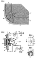
- FIGS. 4 and 5 The shape of the die or tool 2, also the shape, is shown in FIGS. 4 and 5 in conjunction with FIG called, more in detail, whereby it can be seen that the outer circular tool 2 an elongated Interior or molding space 21 of square cross-section, for the one having a square cross-section Workpiece 1, as well as the cavity 7 branching therefrom of rectangular cross section for the one to be produced Bulge or branch 12 has the workpiece 1.
- a blank i.e. a hollow profile with a square cross section, from which the workpiece 1 with the Branch 12 is to be formed, inserted into the tool 2, after which the two press rams 3, 4 engage be brought to the end faces of the blank, with a tight seal on these end faces with the help of the press ram 3, 4 is brought about.
- the press rams 3, 4 on their end faces on the outer circumference be graduated, i.e. have step-shaped heels, in particular a height in the range of 5% to 100% of have mean wall thickness of the blank, and with which the material of the blank is plasticized during pressing, whereby a metallic seal is brought about.
- the pump 18 is switched on, in particular to pressure medium Water to supply the interior of the blank via the pressure medium supply line 17.
- the valve 16 on the The outlet side is in the "fill" position as shown, with this position simply being ascertained can be when the pressure medium emerges on the outlet side (as illustrated schematically in FIG. 3 with the outlet line 22) is).
- the control valve 16 is then moved upward into its "pressing" position as shown in FIG the output side is connected to the pressure valve 14 instead of the outlet line 22.
- the pressure of the pressure medium is now increased with the aid of the pump 18, and the pressing process can begin by driving the ram 3, 4 with the pressing force Fp1 or Fp2.
- Fp1 or Fp2 the pressing force
- the internal pressure pi (s) is continuously adjusted with the help of the pressure valve 14, whereby beginning with a preload at the beginning of the pressing, an increase in pressure to approximately twice Bias pressure can be provided, after which, for example, in a next section of the process a linear pressure increase to approximately ten times the pressure value - up to approximately the middle of the entire pressing process, i.e. half way the ram 3, 4- is provided; afterwards the internal pressure pi is increased, for example this maximum value now reached is kept constant.
- the bulge or Branch 12 is produced, with the counter-punch 13 having a likewise preferably path-dependent Controlled counter-holding force Fg is countered so as to prevent the bulge 12 from bursting or bursting.
- FIG. 6 shows a diagram of the internal pressure pi (in bar) over the path s (in mm) of the press rams 3, 4, the internal pressure pi generally being controlled as a function of the path as set out above.
- a prestressing pressure pv of, for example, 130 bar is set at the beginning of the pressing process, and at the beginning of the Pressing, the internal pressure pi increases to a value pa of e.g. 250 bar at up to a press ram path s of 7.5 mm is kept constant (phase of molding on the punch 13 and beginning bulge with small ones Strains).
- a workpiece 1 'can also have two Branches 12 ', 12' 'can be produced, as illustrated in the diagram of FIG.
- the tool 2 ' has in In this case, two cavities 7 ', 7' 'for the bulges or branches 12', 12 '', in which cavities 7 ', 7' ', corresponding counter-stamps 13', 13 '' as variable tool parts with a contact force Fg.1 (s) or Fg2 (s) are kept mobile.
- the press rams 3, 4 are applied to the workpiece 1 'with a pressing force Fp1 or Fp2.
- a supply line 23 is provided for filling the workpiece 1 ′ with water, to which the pressure medium supply line 17 Connected via a directional valve 24 and on the one hand via the pump 18 or on the other hand directly via a check valve 25 is.
- a pressure valve 14 ' is in turn connected to the pressure medium discharge line 15, which in the present case Case via a hydraulic control circuit with an adjustable pump 26 and a control line 27, in the one Check valve 28 is added, can be adjusted in pressure.
- a control and regulating unit 30 which the process water biasing pump 18th and the pump 26 adjustable in terms of the outlet pressure in the control circuit for the pressure valve 14 'for the purpose of adjustment of the respective internal pressure pi.
- Input variables for the control and regulating unit 30 are the path s the press ram 3, 4 (it is usually sufficient to take the path of a ram, e.g. 3, and the unit 30 ) and the internal pressure pi (s), which is also measured for safety reasons.
- the quantities Fp1, Fp2, Fg1 and Fg2 according to Fig. 7 are both detected and set, e.g. simply path dependent or with an additional readjustment (actual value-setpoint comparison), as described in more detail below will be explained in more detail with reference to the flow diagrams from FIGS. 8 to 10.
- unit 30 could be a PLC (programmable logic controller) unit act with the simply path-dependent the pressures (press forces Fp1, Fp2, Fg1, Fg2) and in particular the internal pressure pi can be set.
- PLC programmable logic controller
- FIG. 8 A corresponding flow diagram is shown in FIG. 8, which is such a simple path-dependent one Pressure guidance and counterforce guidance included.
- the inputs for v1 are made (Valve for the press ram 3, for the press shaft Fp1), for v2 (valve for the press ram, 4, for the press force Fp2), for the Internal pressure pi (s), for the counterforce Fg1 (s) and for the counterforce Fg2 (s).
- the workpiece 1 ' is filled in block 33 until the pressure medium emerges at the outlet of the pressure valve 14'.
- the valves v1 and v2 are set in accordance with block 35 in FIG. This begins the actual pressing process, during which the path s of the press ram (s) 3, 4 is measured, s.
- the pressure relief valve 14 'for the internal pressure pi is continuously set depending on the path s, block 37 in FIG. 8.
- block 39 it is queried cyclically whether the press ram path s has reached the end value for it, ie whether the pressing process can be ended or not. If this is not the case, the system returns to block 36, etc. at 40, and a new path measurement, pressure relief valve position, etc. is carried out 8 is indicated at 41.
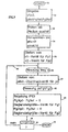
- Step 9 illustrates in a further flowchart a somewhat modified process flow compared to FIG. 8, as here an internal pressure-dependent regulation for the counter-stamping forces Fg1 and Fg2 takes place.
- the Steps 31 to 37 are the same as in the flow chart according to FIG. 8, so that there will be a new description of them can spare.
- step 37 setting the internal pressure pi
- the internal pressure pi is measured Counter-holding force Fg1 of the one counter-holding die 13 'and the counter-holding force Fg2 of the second counter-holding die 13 '' (block 42 in Fig. 9). This is followed by a control of Fg1 and Fg2, i.e.
- a setpoint Fg1 (pi) and a setpoint Fg2 (pi) are determined and compared with the actual value Fg1 ist and Fg2ist, respectively.
- the valves for the actuation of the counterhold punches 13 'or 13' 'are set Block 43 in Fig. 9. Then it is queried again in block 39 whether the press punches have already reached their end of travel, and if no, return to block 39; if yes, go to end 41.
- FIG. 11 schematically shows a device with a Welkzeug 2 without variable tool parts (counter-holding stamp) shown in a cavity 7, wherein, for example, a hemispherical bulge 12 on the workpiece 1 'at Presses to be generated with the help of the press rams 3, 4.
- a heat treatment of the blank to be pressed is desired before the pressing process - in the As a rule, such a heat treatment is preferred for soft annealing - the duration and the degree of depend Heat treatment (temperature) of course from the respective blank, in particular from the respective material from.
- a heat treatment will have to be carried out in such a way that the blank is long enough, e.g. 1 heated to a few 100 ° C in an annealing furnace for up to 2 hours, after which it is allowed to cool in air; before that soft annealed material again, due to the outsourcing of alloy components to the grain boundaries, to duclility would then lose the pressing process - e.g. approx. 2 or 3 hours after the heat treatment.
- the upright arrangement of the tool shown in FIGS. 3 and 7 with the supply of the pressure medium from below has the advantage that when filling air bubbles or gas bubbles in general can rise, so that the interior of the blank or workpiece 1 or 1 'can be filled without gas bubbles.
- Adequate lubrication is also important when pressing, especially in areas with a large curvature, where the material has to flow around tight radii or in tight threads.
- a corresponding lubricant application is therefore particularly important on edges - including the blank. In particular, it is advantageous to reduce the edge area by approx. Apply 50% more lubricant.
- a hollow profile blank with a square cross-section was pressed from an AlMgSi 0.5 material, the dimensions of the blank being as follows: external dimensions 30 ⁇ 30 mm 2 , wall thickness 2 mm, corner radius 2 mm, length 155 mm.
- the tensile strength for AlMgSi 0.5 is approx. 200 N / mm 2 .
- the blank was heated in an annealing furnace to 400 ° C. for 100 minutes before being pressed and then in air cooled down.
- the press processing took place after approx. 3 hours.
- a preload pressure of 130 bar was set for this (at the beginning of the pressing process), and the maximum internal pressure which is reached in the second half of the process phase where large expansions of the workpiece material were required was 2000 bar.
- the pressing speed was 5 mm / s, and the counter-holding force of the one counter-holding die for the production of a workpiece with one branch, square as the starting profile, was 10 kN.
- the workpiece produced was a T-piece, similar to that shown in FIG. 3, with a branch length of 53 mm (measured against the rear wall) and the workpiece had a final length of 90 mm. In the area the corner radius was 3mm.
- pressure valve 14 or 14 ' A wide variety of conventional pressure valve types can be used as pressure valve 14 or 14 ', such as in particular also electromagnetically in addition to the hydraulically operated pressure valve 14 ′ shown in FIG. 7 actuated pressure valves.
- the control and regulating unit 30 can furthermore in a conventional manner with corresponding electrical Circuits are realized, such as in particular A / D converters, D / A converters, comparators and / or microprocessors.
- electrical Circuits such as in particular A / D converters, D / A converters, comparators and / or microprocessors.
- Such regulating and control units are known per se in conventional presses, so that a detailed explanation can be omitted here.
Landscapes
- Engineering & Computer Science (AREA)
- Mechanical Engineering (AREA)
- Physics & Mathematics (AREA)
- Fluid Mechanics (AREA)
- Shaping Metal By Deep-Drawing, Or The Like (AREA)
- Forging (AREA)
- Superconductors And Manufacturing Methods Therefor (AREA)
Claims (12)
- Procédé de déformation de profilés métalliques creux dans un outillage, avec assistance par une pression intérieure, pour réaliser des pièces (1) pourvues de renflements, de collets en saillie, d'embranchements ou analogues, dans lequel on introduit un agent de pression liquide à l'intérieur d'une ébauche disposée dans l'outillage (2) et amenée en prise, par ses faces d'extrémité, avec au moins un poinçon de compression mobile et un outil de retenue fixe, de préférence avec deux poinçons de compression mobile (3, 4), on comprime l'ébauche, à l'aide du ou des poinçons de compression (3, 4), de façon que cette ébauche s'épanouisse dans au moins une cavité (7) de l'outillage, et on commande la pression de l'agent de pression à l'intérieur de l'ébauche fermée par le poinçon de compression et l'outil de retenue fixe ou par les poinçons de compression (3, 4), en fonction de l'avancement du processus de compression, de préférence en fonction de la course (5) d'un poinçon de compression, caractérisé en ce que, dans des étapes du procédé correspondant à de faibles allongements (ϕ) du matériau, on règle la pression (pi) de l'agent de pression de façon que la contrainte de référence développée dans la pièce à partir de l'état de tension dans l'espace atteigne à peu près exactement la résistance à la déformation (kf) du matériau, tandis que, dans des étapes du procédé correspondant à de grands allongements (ϕ), on augmente la pression (pi) de l'agent de pression pour augmenter suffisamment l'allongement à la rupture du matériau par réduction de la contrainte moyenne (?).
- Procédé suivant la revendication 1, caractérisé en ce que, au début du processus de compression, l'agent de pression est amené à une surpression faible (pa), par exemple de l'ordre de 300 à 600 bars, et vers l'extrémité du processus de compression, à la valeur maximale (pe), par exemple de l'ordre de quelques kilobars.
- Procédé suivant la revendication 1 ou 2, caractérisé en ce que, pendant le processus de compression, l'agent de pression est amené à une pression maximale (pe) d'au moins 80% de la résistance à la traction du matériau de l'ébauche.
- Procédé suivant l'une des revendications 1 à 3, caractérisé en ce que la pression (pi) de l'agent de pression est réglée, dans des phases de compression dans lesquelles le matériau de l'ébauche flue autour de petits rayons de courbure de l'outillage (2), à 5% à 40%, suivant l'épaisseur de paroi (w), de la pression maximale atteinte pendant la compression.
- Procédé suivant l'une des revendications 1 à 4, caractérisé en ce que l'agent de pression, avant la compression de l'ébauche, est déjà amené à une pression élevée de pré-tension (pv) égale de préférence à 5% à 20%, en particulier à environ 10%, de la pression maximale (pe) atteinte pendant la compression, par exemple à une valeur de l'ordre de 100 à 1000 bars.
- Procédé suivant l'une des revendications 1 à 5, caractérisé en ce que, avant le processus de compression, on remplit l'ébauche avec l'agent de pression de manière à en éliminer les inclusions gazeuses, et en ce que l'agent de pression est amené par une pompe (18) à une pression élevée (pi).
- Procédé suivant l'une des revendications 1 à 6, caractérisé en ce que, dans le cas de matériaux d'ébauche qui comprennent des transferts de constituants d'alliage aux joints des grains, en particulier d'alliages d'aluminium à haute résistance, on effectue avant le processus de compression un traitement thermique qui, en provoquant l'inclusion de ces constituants d'alliage dans le réseau cristallin, augmente la ductilité du matériau, et en ce qu'on procède à la compression à l'intérieur d'un intervalle de temps prédéterminé, par exemple de 1 heure à 4 heures après le traitement thermique, mais avant que se produise un nouveau transfert des constituants d'alliage aux joints des grains.
- Procédé suivant la revendication 7, caractérisé en ce qu'on chauffe des ébauches en alliages AlMgSi vers 400°C pendant environ 100 mn dans un four à malléabiliser, puis on les refroidit dans de l'air et, environ 3 heures après la fin du traitement thermique dans le four de malléabilisation, on les comprime.
- Procédé suivant l'une des revendications 1 à 8, dans lequel, lors de la compression de l'ébauche dans la ou dans chaque cavité (7) de l'outillage dans laquelle on fait pénétrer par déformation le matériau de l'ébauche, on réalise une retenue au moyen d'un outil de retenue variable (13) dont la forme en section correspond à la ou à chaque partie à déformer par épanouissement, caractérisé en ce qu'on effectue la retenue au moyen de l'outil ou de chaque outil variable (13) commandé par pression et/ou par déplacement, et on définit les forces ainsi appliquées à la pièce de façon que la contrainte moyenne se développant dans l'ensemble dans la pièce (1) (la partie hydrostatique de la contrainte) soit réduite dans une mesure telle que l'allongement à la rupture ainsi défini soit supérieur au plus grand allongement qui se produit dans la partie de la pièce qui s'appuie sur l'outil variable (13).
- Procédé suivant la revendication 9, caractérisé en ce que la force (Fg) développée par l'outil de retenue variable (13) est réglée à au moins 5% de la force exercée sur la partie à épanouir par la pression intérieure régnant dans l'ébauche.
- Procédé suivant la revendication 9 ou 10, caractérisé en ce que, dans le cas où l'on réalise simultanément plusieurs renflements, embranchements ou analogues (12, 12') et, de façon correspondante, on utilise plusieurs outils de retenue variables (13, 13') commandés par pression, on procède en outre, pour leur commande de pression, à une surveillance ou mesure de déplacement, afin d'adapter leur commande de pression lors de déplacements à vitesse variable des outils de retenue variables (13, 13').
- Procédé suivant l'une des revendications 1 à 11, caractérisé en ce qu'on amène au moins 50% de plus de lubrifiant dans des zones de l'ébauche ou de l'outillage ayant des petits rayons de courbure superficiels, en particulier à l'emplacement d'arêtes arrondies, par rapport à la quantité de lubrifiant amenée dans les autres parties de l'ébauche ou de l'outillage (2).
Applications Claiming Priority (3)
| Application Number | Priority Date | Filing Date | Title |
|---|---|---|---|
| AT1346/93 | 1993-07-08 | ||
| AT0134693A ATA134693A (de) | 1993-07-08 | 1993-07-08 | Verfahren zur innendruckgestützten umformung von metallischen hohlprofilen sowie vorrichtung zur durchführung dieses verfahrens |
| AT134693 | 1993-07-08 |
Publications (3)
| Publication Number | Publication Date |
|---|---|
| EP0633075A1 EP0633075A1 (fr) | 1995-01-11 |
| EP0633075B1 EP0633075B1 (fr) | 1997-04-09 |
| EP0633075B2 true EP0633075B2 (fr) | 1999-12-22 |
Family
ID=3511912
Family Applications (1)
| Application Number | Title | Priority Date | Filing Date |
|---|---|---|---|
| EP94890118A Expired - Lifetime EP0633075B2 (fr) | 1993-07-08 | 1994-07-08 | Procédé pour le formage de profils creux métalliques soutenu par pression interne |
Country Status (4)
| Country | Link |
|---|---|
| EP (1) | EP0633075B2 (fr) |
| AT (2) | ATA134693A (fr) |
| DE (1) | DE59402350D1 (fr) |
| ES (1) | ES2102801T5 (fr) |
Families Citing this family (4)
| Publication number | Priority date | Publication date | Assignee | Title |
|---|---|---|---|---|
| US6128936A (en) * | 1998-09-09 | 2000-10-10 | Kabushiki Kaisha Opton | Bulging device and bulging method |
| FR2787357B1 (fr) | 1998-12-18 | 2001-03-16 | Tubes Et Formes | Procede et dispositif de realisation par hydroformage d'un piquage incline a partir d'un tube metallique |
| US7832244B2 (en) | 2008-03-13 | 2010-11-16 | Gm Global Technology Operations, Inc. | Controlling fluid pressure in a hydroforming process |
| CN120001855A (zh) * | 2025-04-17 | 2025-05-16 | 江西赣羽装饰工程有限公司 | 一种门窗加工用压制弯折装置 |
Citations (2)
| Publication number | Priority date | Publication date | Assignee | Title |
|---|---|---|---|---|
| US2331430A (en) † | 1941-08-27 | 1943-10-12 | Chase Brass & Copper Co | Apparatus for making hollow articles |
| DE1452547B2 (de) † | 1963-12-21 | 1970-06-11 | The Agency Of Industrial Science And Technology, Tokio | Hydraulische Druckregelungseinrichtung an einer Vorrichtung zur Herstellung eines verzweigten Rohranschlusses |
Family Cites Families (3)
| Publication number | Priority date | Publication date | Assignee | Title |
|---|---|---|---|---|
| FR1048482A (fr) * | 1950-09-18 | 1953-12-22 | Ici Ltd | Fabrication de raccords de tuyaux à branchements |
| US3350905A (en) * | 1963-12-21 | 1967-11-07 | Agency Ind Science Techn | Liquid pressure bulge forming apparatus |
| FR2477918A1 (fr) * | 1980-03-13 | 1981-09-18 | Vallourec | Procede perfectionne pour fabriquer des pieces par hydroflambage et dispositif pour la mise en oeuvre de ce procede |
-
1993
- 1993-07-08 AT AT0134693A patent/ATA134693A/de not_active IP Right Cessation
-
1994
- 1994-07-08 DE DE59402350T patent/DE59402350D1/de not_active Expired - Lifetime
- 1994-07-08 ES ES94890118T patent/ES2102801T5/es not_active Expired - Lifetime
- 1994-07-08 EP EP94890118A patent/EP0633075B2/fr not_active Expired - Lifetime
- 1994-07-08 AT AT94890118T patent/ATE151317T1/de not_active IP Right Cessation
Patent Citations (2)
| Publication number | Priority date | Publication date | Assignee | Title |
|---|---|---|---|---|
| US2331430A (en) † | 1941-08-27 | 1943-10-12 | Chase Brass & Copper Co | Apparatus for making hollow articles |
| DE1452547B2 (de) † | 1963-12-21 | 1970-06-11 | The Agency Of Industrial Science And Technology, Tokio | Hydraulische Druckregelungseinrichtung an einer Vorrichtung zur Herstellung eines verzweigten Rohranschlusses |
Non-Patent Citations (10)
| Title |
|---|
| "Technologie, Ausrüstung, Organisation und Wirtschaft der Maschinenbauproduktion", Serie 3, Technologie und Ausrüstung der Schmieden-Umformproduktion, VNIITEMR, Übersichtsinformation, Ausgabe 4, Moskau 1988 † |
| Berg- und Hüttenmännische Monatshefte, 1987, Seiten 78-82 † |
| Dissertation von Ch. Hessler, TH Darmstadt 1991,"Beitrag zur Entwicklung des Hydraulischen-Rohr-Innendruck-Umformens" † |
| Dissertation von P.Bieling,Universität-GH Paderborn 1992, "Untersuchung zum Aufweitstauchen von Rohren zu Hohlwellen" † |
| Fortschrittsberichte VDI, Reihe 2:Fertigungstechnik, Nr. 142, VDI-Verlag, Düsseldorf 1987,"Aufweitstauchen von Rohren durch Innenhochdruckumformen", von F.Klaas † |
| Industrie-Anzeiger, Werkzeugmaschine und Fertigungstechnik, Teil II:Umformtechnik, 88. Jahrgang, Nr. 37 (1966), Seiten 107-110, Nr. 48 (1968), Seiten 137-140 † |
| Lexikon Werkstofftechnik, VDI-Verlag, Düsseldorf 1991, Seiten 327,328 † |
| VDI-Berichte Nr. 614,VDI-Verlag, Düsseldorf 1986, "Technologie und Maschinenausrüstungfür automatisiertes Umformen von T-Rohrstücken und Reduzierungen durch Flüssigkeit", von J. Tomasek † |
| Zeitschrift "Bänder, Bleche, Rohre," Nr. 8-1991, Seiten 19-29, "Bau von Werkzeugen und Maschinen zum Innenhochdruckumformen", von F. Dohmann und K.-U. Dudziak † |
| Zeitschrift "fluid", Oktober 1991, Seiten 20-22 † |
Also Published As
| Publication number | Publication date |
|---|---|
| ATE151317T1 (de) | 1997-04-15 |
| ES2102801T5 (es) | 2000-04-16 |
| EP0633075B1 (fr) | 1997-04-09 |
| ES2102801T3 (es) | 1997-08-01 |
| DE59402350D1 (de) | 1997-05-15 |
| EP0633075A1 (fr) | 1995-01-11 |
| ATA134693A (de) | 1999-10-15 |
Similar Documents
| Publication | Publication Date | Title |
|---|---|---|
| DE69316949T2 (de) | Vorrichtung und Verfahren zum Formen und hydraulischen Lochen eines rohrförmigen Rahmens | |
| DE69010429T2 (de) | Vorrichtung und Verfahren zum Formen eines rohrförmigen Rahmens. | |
| DE3931320C1 (fr) | ||
| DE69817947T2 (de) | Vorrichtung zum Hydroformen eines Rohres aus Metall | |
| DE3742869B4 (de) | Rohrförmige Stabilisatorstange und Verfahren zu deren Herstellung | |
| EP2512702A1 (fr) | Procédé et dispositif de fabrication d'un élément en demi-coque | |
| EP2529849A2 (fr) | Dispositif et procédé de fabrication de tuyaux fendus à partir de plaques de tôle | |
| EP1820577A1 (fr) | Machine pour la réalisation de profilés avec une section variable dans le sens de la longueur et profilés obtenus par une telle machine | |
| EP1986801A1 (fr) | PROCEDE ET DISPOSITIF DE Formation D'UNE DECOUPE OU D'UNE PERFORATION DANS LA PAROI D'UN COMPOSANT FORME PAR UN PROCEDE DE FACONNAGE SOUS HAUTE PRESSION INTERIEURE | |
| EP2344288A2 (fr) | Procédé et dispositif pour réaliser un filetage extérieur sans enlèvement de matière sur des pièces creuses en métal | |
| DE1299854B (de) | Ziehverfahren fuer plattenfoermige Rohlinge aus einem druckplastifizierbaren Feststoff und Einrichtung zur Durchfuehrung des Verfahrens | |
| DE10334483B4 (de) | Verfahren und Ziehwerkzeug zum Herstellen eines Blechteils aus einer Platine | |
| DE102017102356B3 (de) | Verfahren und Vorrichtung zum Herstellen eines Kragens an einem Werkstück | |
| DE4401674C2 (de) | Verfahren sowie Vorrichtung zum Lochen von Werkstücken | |
| DE3019593A1 (de) | Verfahren und vorrichtung zum herstellen von dickwandigen stahlrohren | |
| EP2030703A1 (fr) | Procédé et dispositif de laminage transversal d'arbres creux ou de pièces creuses cylindriques dégradés d'un tuyau | |
| DE102006003268A1 (de) | Verfahren sowie Tiefziehvorrichtung zum Tiefziehen von Metallblechen | |
| EP0633075B2 (fr) | Procédé pour le formage de profils creux métalliques soutenu par pression interne | |
| EP2272601B1 (fr) | Procédé d'hydroformage | |
| EP3898025A1 (fr) | Procédé pour produire une soupape à tige creuse pour des moteurs à combustion interne | |
| EP0849011A1 (fr) | Procédé et installation pour produire des profilés creux avec des extensions de section aux extrémités | |
| DE2554609C2 (de) | Verfahren und Vorrichtung zur Herstellung von Steuerköpfen für Fahrräder | |
| DE102004006126A1 (de) | Presse mit verriegeltem Stößel | |
| DE102016114934B3 (de) | Verfahren und Vorrichtung zur Herstellung eines runden Hohlprofils | |
| WO2005075183A1 (fr) | Presse a coulisseau verrouille |
Legal Events
| Date | Code | Title | Description |
|---|---|---|---|
| PUAI | Public reference made under article 153(3) epc to a published international application that has entered the european phase |
Free format text: ORIGINAL CODE: 0009012 |
|
| AK | Designated contracting states |
Kind code of ref document: A1 Designated state(s): AT CH DE ES FR GB IT LI SE |
|
| 17P | Request for examination filed |
Effective date: 19950303 |
|
| GRAG | Despatch of communication of intention to grant |
Free format text: ORIGINAL CODE: EPIDOS AGRA |
|
| GRAH | Despatch of communication of intention to grant a patent |
Free format text: ORIGINAL CODE: EPIDOS IGRA |
|
| 17Q | First examination report despatched |
Effective date: 19960712 |
|
| GRAH | Despatch of communication of intention to grant a patent |
Free format text: ORIGINAL CODE: EPIDOS IGRA |
|
| GRAH | Despatch of communication of intention to grant a patent |
Free format text: ORIGINAL CODE: EPIDOS IGRA |
|
| GRAA | (expected) grant |
Free format text: ORIGINAL CODE: 0009210 |
|
| AK | Designated contracting states |
Kind code of ref document: B1 Designated state(s): AT CH DE ES FR GB IT LI SE |
|
| REF | Corresponds to: |
Ref document number: 151317 Country of ref document: AT Date of ref document: 19970415 Kind code of ref document: T |
|
| REG | Reference to a national code |
Ref country code: CH Ref legal event code: EP |
|
| REF | Corresponds to: |
Ref document number: 59402350 Country of ref document: DE Date of ref document: 19970515 |
|
| RAP2 | Party data changed (patent owner data changed or rights of a patent transferred) |
Owner name: ELB-FORM GMBH |
|
| REG | Reference to a national code |
Ref country code: CH Ref legal event code: NV Representative=s name: ABATRON-PATENTBUERO AG |
|
| REG | Reference to a national code |
Ref country code: ES Ref legal event code: FG2A Ref document number: 2102801 Country of ref document: ES Kind code of ref document: T3 |
|
| GBT | Gb: translation of ep patent filed (gb section 77(6)(a)/1977) |
Effective date: 19970715 |
|
| ET | Fr: translation filed | ||
| PLBI | Opposition filed |
Free format text: ORIGINAL CODE: 0009260 |
|
| PLBQ | Unpublished change to opponent data |
Free format text: ORIGINAL CODE: EPIDOS OPPO |
|
| PLBI | Opposition filed |
Free format text: ORIGINAL CODE: 0009260 |
|
| PLBF | Reply of patent proprietor to notice(s) of opposition |
Free format text: ORIGINAL CODE: EPIDOS OBSO |
|
| 26 | Opposition filed |
Opponent name: DAIMLER-BENZ AKTIENGESELLSCHAFT FTP/S, C106 Effective date: 19980109 |
|
| 26 | Opposition filed |
Opponent name: SIEMPELKAMP PRESSEN SYSTEME GMBH & CO. Effective date: 19980108 Opponent name: DAIMLER-BENZ AKTIENGESELLSCHAFT FTP/S, C106 Effective date: 19980109 |
|
| PLBF | Reply of patent proprietor to notice(s) of opposition |
Free format text: ORIGINAL CODE: EPIDOS OBSO |
|
| PLBF | Reply of patent proprietor to notice(s) of opposition |
Free format text: ORIGINAL CODE: EPIDOS OBSO |
|
| PLBF | Reply of patent proprietor to notice(s) of opposition |
Free format text: ORIGINAL CODE: EPIDOS OBSO |
|
| PLAB | Opposition data, opponent's data or that of the opponent's representative modified |
Free format text: ORIGINAL CODE: 0009299OPPO |
|
| R26 | Opposition filed (corrected) |
Opponent name: DAIMLERCHRYSLER AG INTELLECTUAL PROPERTY MANAGEMEN Effective date: 19980109 |
|
| PLAW | Interlocutory decision in opposition |
Free format text: ORIGINAL CODE: EPIDOS IDOP |
|
| PGFP | Annual fee paid to national office [announced via postgrant information from national office to epo] |
Ref country code: CH Payment date: 19990625 Year of fee payment: 6 |
|
| PGFP | Annual fee paid to national office [announced via postgrant information from national office to epo] |
Ref country code: SE Payment date: 19990705 Year of fee payment: 6 |
|
| PGFP | Annual fee paid to national office [announced via postgrant information from national office to epo] |
Ref country code: AT Payment date: 19990723 Year of fee payment: 6 |
|
| PLAW | Interlocutory decision in opposition |
Free format text: ORIGINAL CODE: EPIDOS IDOP |
|
| RTI2 | Title (correction) |
Free format text: METHOD FOR FORMING HOLLOW METALLIC PROFILES SUPPORTED BY INTERNAL PRESSURE |
|
| PUAH | Patent maintained in amended form |
Free format text: ORIGINAL CODE: 0009272 |
|
| STAA | Information on the status of an ep patent application or granted ep patent |
Free format text: STATUS: PATENT MAINTAINED AS AMENDED |
|
| 27A | Patent maintained in amended form |
Effective date: 19991222 |
|
| AK | Designated contracting states |
Kind code of ref document: B2 Designated state(s): AT CH DE ES FR GB IT LI SE |
|
| REG | Reference to a national code |
Ref country code: CH Ref legal event code: AEN Free format text: AUFRECHTERHALTUNG DES PATENTES IN GEAENDERTER FORM |
|
| ITF | It: translation for a ep patent filed | ||
| GBTA | Gb: translation of amended ep patent filed (gb section 77(6)(b)/1977) | ||
| REG | Reference to a national code |
Ref country code: ES Ref legal event code: DC2A Kind code of ref document: T5 Effective date: 20000313 |
|
| ET3 | Fr: translation filed ** decision concerning opposition | ||
| PG25 | Lapsed in a contracting state [announced via postgrant information from national office to epo] |
Ref country code: AT Free format text: LAPSE BECAUSE OF NON-PAYMENT OF DUE FEES Effective date: 20000708 |
|
| PG25 | Lapsed in a contracting state [announced via postgrant information from national office to epo] |
Ref country code: SE Free format text: LAPSE BECAUSE OF NON-PAYMENT OF DUE FEES Effective date: 20000709 |
|
| PG25 | Lapsed in a contracting state [announced via postgrant information from national office to epo] |
Ref country code: LI Free format text: LAPSE BECAUSE OF NON-PAYMENT OF DUE FEES Effective date: 20000731 Ref country code: CH Free format text: LAPSE BECAUSE OF NON-PAYMENT OF DUE FEES Effective date: 20000731 |
|
| REG | Reference to a national code |
Ref country code: CH Ref legal event code: PL |
|
| EUG | Se: european patent has lapsed |
Ref document number: 94890118.6 |
|
| REG | Reference to a national code |
Ref country code: GB Ref legal event code: IF02 |
|
| PLAB | Opposition data, opponent's data or that of the opponent's representative modified |
Free format text: ORIGINAL CODE: 0009299OPPO |
|
| PGFP | Annual fee paid to national office [announced via postgrant information from national office to epo] |
Ref country code: ES Payment date: 20130724 Year of fee payment: 20 Ref country code: DE Payment date: 20130731 Year of fee payment: 20 |
|
| PGFP | Annual fee paid to national office [announced via postgrant information from national office to epo] |
Ref country code: GB Payment date: 20130725 Year of fee payment: 20 Ref country code: FR Payment date: 20130730 Year of fee payment: 20 |
|
| PGFP | Annual fee paid to national office [announced via postgrant information from national office to epo] |
Ref country code: IT Payment date: 20130723 Year of fee payment: 20 |
|
| REG | Reference to a national code |
Ref country code: DE Ref legal event code: R071 Ref document number: 59402350 Country of ref document: DE |
|
| REG | Reference to a national code |
Ref country code: DE Ref legal event code: R071 Ref document number: 59402350 Country of ref document: DE |
|
| REG | Reference to a national code |
Ref country code: GB Ref legal event code: PE20 Expiry date: 20140707 |
|
| PG25 | Lapsed in a contracting state [announced via postgrant information from national office to epo] |
Ref country code: DE Free format text: LAPSE BECAUSE OF EXPIRATION OF PROTECTION Effective date: 20140709 |
|
| REG | Reference to a national code |
Ref country code: ES Ref legal event code: FD2A Effective date: 20141120 |
|
| PG25 | Lapsed in a contracting state [announced via postgrant information from national office to epo] |
Ref country code: GB Free format text: LAPSE BECAUSE OF EXPIRATION OF PROTECTION Effective date: 20140707 |
|
| PG25 | Lapsed in a contracting state [announced via postgrant information from national office to epo] |
Ref country code: ES Free format text: LAPSE BECAUSE OF EXPIRATION OF PROTECTION Effective date: 20140709 |