EP0633084A1 - Dispositif de perçage à faire des trous à chambrage - Google Patents
Dispositif de perçage à faire des trous à chambrage Download PDFInfo
- Publication number
- EP0633084A1 EP0633084A1 EP94106713A EP94106713A EP0633084A1 EP 0633084 A1 EP0633084 A1 EP 0633084A1 EP 94106713 A EP94106713 A EP 94106713A EP 94106713 A EP94106713 A EP 94106713A EP 0633084 A1 EP0633084 A1 EP 0633084A1
- Authority
- EP
- European Patent Office
- Prior art keywords
- drilling
- drilling spindle
- bearing
- deflection element
- spindle
- Prior art date
- Legal status (The legal status is an assumption and is not a legal conclusion. Google has not performed a legal analysis and makes no representation as to the accuracy of the status listed.)
- Granted
Links
- 238000005553 drilling Methods 0.000 title claims abstract description 53
- 230000005540 biological transmission Effects 0.000 claims description 2
- 239000000919 ceramic Substances 0.000 claims 1
- 239000004567 concrete Substances 0.000 claims 1
- 239000004575 stone Substances 0.000 claims 1
- 238000000034 method Methods 0.000 description 6
- 229910003460 diamond Inorganic materials 0.000 description 5
- 239000010432 diamond Substances 0.000 description 5
- 238000005520 cutting process Methods 0.000 description 2
- 230000002028 premature Effects 0.000 description 2
- 238000004519 manufacturing process Methods 0.000 description 1
- 238000003892 spreading Methods 0.000 description 1
- 238000003756 stirring Methods 0.000 description 1
- 238000003860 storage Methods 0.000 description 1
Images


Classifications
-
- B—PERFORMING OPERATIONS; TRANSPORTING
- B23—MACHINE TOOLS; METAL-WORKING NOT OTHERWISE PROVIDED FOR
- B23B—TURNING; BORING
- B23B51/00—Tools for drilling machines
- B23B51/0018—Drills for enlarging a hole
- B23B51/0027—Drills for enlarging a hole by tool swivelling
Definitions
- the invention relates to a device for producing boreholes with an undercut according to the preamble of claim 1.
- Such drill holes with an undercut can also be made in facade panels or the like, but the undercuts there must be carried out very precisely so that when the expansion anchor is inserted and spread out, the expansion pressure is not too high. One too high spreading pressure can cause part of the facade panel to burst.
- these devices are designed in such a way that automatic, machine-controlled swiveling is made possible.
- Drilling tools are also used which have a drill head equipped with diamond chips. When the drilling tool clamped in alignment with the drive axis of the drilling machine is immersed in the facade panel, the entire end face of the truncated cone-shaped drilling head comes into engagement. This requires a high contact pressure of the drilling tool, which, due to the lower cutting speed in the center of the end face of the drilling tool, leads to premature dulling of the diamond chips. This significantly reduces the service life of the drilling tool.
- the invention has for its object to provide a device for producing boreholes with an undercut, in which the wobble movement required to rub out an undercut is carried out mechanically.
- the wobble movement during the drilling process has the advantage that the drilling can be carried out more easily and thus more gently. Without such a wobbling movement, low cutting speeds occur in the center of the drill head equipped with diamond chips, which lead to premature dulling of the diamond chips.
- the deflection element preferably rotates at a lower speed than the drilling spindle.
- the drilling spindle and deflecting element can be driven by separate drive motors, but it is more advantageous to provide a common drive which drives the drilling spindle and deflecting element at different speeds via belt or gear drives.
- a common drive can be realized more compactly, with less weight and less costs.
- the lower weight is particularly advantageous for the generation of the wobble movement, since a lower mass contributes to the fact that higher wobble speeds can be achieved.
- the deflecting element preferably protrudes from a rotating ring which surrounds the drilling spindle. To generate the The rotary ring is now set in rotation, the deflecting element projecting from it pivoting the pivotably mounted drilling spindle from the vertical position.
- the deflection element can be a roller standing on the ring or a bearing element, for example a four-point bearing. Such a four-point bearing can be operated much more wear-free than a roller, but a deflection element designed as a roller is less expensive to produce.
- the device shown in FIG. 1 consists of a feed unit 1, a drive unit 2 and a drilling spindle 4 mounted in a swivel device 3.
- the feed device 1 moves the drive device 2 together with the swivel device 3 and the drilling spindle 4 in the vertical direction in order to lower the drilling head 5 in order to create a borehole and then to be able to pull it out again.
- the vertical feed movement is represented by the double arrow 6.
- the drive device 2 consists of a drive motor 7 and a belt transmission 8, which drives the drilling spindle 4 via a belt 9 and a rotary ring 11 via a belt 10.
- the drilling spindle 4 lies in a bearing sleeve 12 which is mounted in a pivot bearing 13.
- the rotating ring 11 is mounted on the bearing sleeve 12 by means of a ball bearing 14.
- the bearing sleeve 12 carries the entire drive device 2 via a holder 15, which is thus pivotably mounted in the pivot bearing 13, just like the drilling spindle 4.
- the swivel range is indicated by broken lines 16.
- the drilling center axis 17 runs through the bearing center 18 of the pivot bearing 13, about which the drilling spindle 4 can be deflected or pivoted.
- the drilling spindle 4 is deflected by a deflection element designed as a roller 19, which projects laterally on the rotating ring 11 and presses against a height-adjustable ring 20 from above.
- a deflection element designed as a roller 19 which projects laterally on the rotating ring 11 and presses against a height-adjustable ring 20 from above.
- the rotary ring 11 is raised on one side, so that the entire arrangement, consisting of the drilling spindle 4 and the drive device 2 in the pivot bearing 13, is tilted slightly.
- a bearing flange 21 fastened to the bearing bush 12 rests on a rubber bearing 22 designed as an O-ring, which thus enables elastic deflection of the bearing bush 12 and the drilling spindle 4 stored therein.
- the ring 20 can be adjusted in height by means of a cylinder 23 in order to obtain a larger or smaller deflection and thus a larger or smaller wobble movement on the drill head 5.
- FIG. 2 shows an embodiment with a bearing element 24 as a deflection element.
- the bearing element 24 is designed as a four-point bearing and is connected to the rotary ring 11 via a lever 25. This is also done here Height adjustment by a cylinder 23 which engages the height-adjustable ring 20.
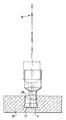
- FIG. 3 illustrates the drilling of a borehole 26 with an undercut 27 in a facade panel 28.
- a drilling head 5 is used for this purpose, which is coated with diamond chips on its end face and on its conical lateral surface.
- the undercut 27 is rubbed out by a wobble movement around the bearing center 18.
- the cylindrical section of the borehole 26 is also created with a wobble movement, which, however, has a smaller amplitude than the wobble movement when the undercut 27 is rubbed out.
- the feed for the drill head 5 is switched off during the wiping out process of the undercut 27.
- the drilling head 5 is part of a drilling tool 55 (FIG. 1) which is known per se and which is connected to the drilling spindle (4).
Landscapes
- Engineering & Computer Science (AREA)
- Mechanical Engineering (AREA)
- Processing Of Stones Or Stones Resemblance Materials (AREA)
- Drilling And Boring (AREA)
- Perforating, Stamping-Out Or Severing By Means Other Than Cutting (AREA)
- Purification Treatments By Anaerobic Or Anaerobic And Aerobic Bacteria Or Animals (AREA)
- Making Paper Articles (AREA)
- Pens And Brushes (AREA)
Applications Claiming Priority (2)
| Application Number | Priority Date | Filing Date | Title |
|---|---|---|---|
| DE4323102A DE4323102A1 (de) | 1993-07-10 | 1993-07-10 | Vorrichtung zur Herstellung von Bohrlöchern mit Hinterschneidung |
| DE4323102 | 1993-07-10 |
Publications (2)
| Publication Number | Publication Date |
|---|---|
| EP0633084A1 true EP0633084A1 (fr) | 1995-01-11 |
| EP0633084B1 EP0633084B1 (fr) | 1996-09-04 |
Family
ID=6492474
Family Applications (1)
| Application Number | Title | Priority Date | Filing Date |
|---|---|---|---|
| EP94106713A Expired - Lifetime EP0633084B1 (fr) | 1993-07-10 | 1994-04-29 | Dispositif de perçage à faire des trous à chambrage |
Country Status (8)
| Country | Link |
|---|---|
| US (1) | US5458530A (fr) |
| EP (1) | EP0633084B1 (fr) |
| JP (1) | JP2736228B2 (fr) |
| AT (1) | ATE142136T1 (fr) |
| BR (1) | BR9402664A (fr) |
| DE (2) | DE4323102A1 (fr) |
| DK (1) | DK0633084T3 (fr) |
| ES (1) | ES2094007T3 (fr) |
Families Citing this family (1)
| Publication number | Priority date | Publication date | Assignee | Title |
|---|---|---|---|---|
| DE102004058812B4 (de) * | 2004-12-07 | 2006-09-28 | Institut für Holztechnologie Dresden gGmbH | Werkzeug zur Erzeugung von Hohlräumen in Werkstoffen, vorzugsweise Sandwichplatten |
Citations (2)
| Publication number | Priority date | Publication date | Assignee | Title |
|---|---|---|---|---|
| EP0442104A2 (fr) * | 1990-02-14 | 1991-08-21 | fischerwerke Artur Fischer GmbH & Co. KG | Dispositif pour la réalisation de perçages épaulés |
| EP0529238A1 (fr) * | 1991-08-22 | 1993-03-03 | fischerwerke Artur Fischer GmbH & Co. KG | Dispositif de fabrication de trous forés avec chambrage |
Family Cites Families (12)
| Publication number | Priority date | Publication date | Assignee | Title |
|---|---|---|---|---|
| US2802320A (en) * | 1956-10-26 | 1957-08-13 | Frank T Donaghy | Grinding attachment for machine tools |
| US3022608A (en) * | 1960-01-11 | 1962-02-27 | Tree Tool & Die Works | Taper grinding tool |
| FR1474967A (fr) * | 1966-02-16 | 1967-03-31 | Trefimetaux | Procédé et machine pour rectifier des pièces telles que des matrices de machines à réduire par laminage |
| US3443399A (en) * | 1966-10-28 | 1969-05-13 | Hall Toledo Corp | High speed universal spindle for a grinding machine |
| CH490933A (de) * | 1968-09-06 | 1970-05-31 | Deckel Fa Friedrich | Schleifmaschine mit einer planetenartig umlaufenden Schleifspindel |
| FR2350924A1 (fr) * | 1976-05-14 | 1977-12-09 | Shc | Machine pour le polissage de la surface interieure d'un moule |
| DE3206387A1 (de) * | 1982-02-22 | 1983-09-01 | Hilti AG, 9494 Schaan | Bohrwerkzeug fuer hinterschnittene bohrungen |
| DE3327409A1 (de) * | 1983-07-29 | 1985-02-07 | Hawera Probst Gmbh + Co, 7980 Ravensburg | Bohrwerkzeug zur herstellung von hinterschneidungen in vorgefertigten bohrungen |
| US4646476A (en) * | 1983-11-07 | 1987-03-03 | Yui George M | Internal hole grinding spindle |
| DE3424918A1 (de) * | 1984-07-06 | 1986-01-16 | Maschinenfabrik Gehring Gmbh & Co Kg, 7302 Ostfildern | Verfahren und vorrichtung zum entgraten einer inneren kante einer bohrung o. dgl. eines werkstueckes |
| DE3704491A1 (de) * | 1987-02-13 | 1988-08-25 | Upat Max Langensiepen Kg | Hinterschnittfbohrer |
| DE4119350A1 (de) * | 1990-11-08 | 1992-05-14 | Fischer Artur Werke Gmbh | Vorrichtung zur herstellung von bohrloechern mit hinterschneidung |
-
1993
- 1993-07-10 DE DE4323102A patent/DE4323102A1/de not_active Withdrawn
-
1994
- 1994-04-29 AT AT94106713T patent/ATE142136T1/de not_active IP Right Cessation
- 1994-04-29 EP EP94106713A patent/EP0633084B1/fr not_active Expired - Lifetime
- 1994-04-29 ES ES94106713T patent/ES2094007T3/es not_active Expired - Lifetime
- 1994-04-29 DK DK94106713.4T patent/DK0633084T3/da active
- 1994-04-29 DE DE59400577T patent/DE59400577D1/de not_active Expired - Fee Related
- 1994-06-07 US US08/254,948 patent/US5458530A/en not_active Expired - Fee Related
- 1994-07-08 BR BR9402664A patent/BR9402664A/pt not_active Application Discontinuation
- 1994-07-11 JP JP6158615A patent/JP2736228B2/ja not_active Expired - Fee Related
Patent Citations (2)
| Publication number | Priority date | Publication date | Assignee | Title |
|---|---|---|---|---|
| EP0442104A2 (fr) * | 1990-02-14 | 1991-08-21 | fischerwerke Artur Fischer GmbH & Co. KG | Dispositif pour la réalisation de perçages épaulés |
| EP0529238A1 (fr) * | 1991-08-22 | 1993-03-03 | fischerwerke Artur Fischer GmbH & Co. KG | Dispositif de fabrication de trous forés avec chambrage |
Also Published As
| Publication number | Publication date |
|---|---|
| JPH0752148A (ja) | 1995-02-28 |
| DE59400577D1 (de) | 1996-10-10 |
| ATE142136T1 (de) | 1996-09-15 |
| JP2736228B2 (ja) | 1998-04-02 |
| ES2094007T3 (es) | 1997-01-01 |
| DK0633084T3 (da) | 1996-09-23 |
| DE4323102A1 (de) | 1995-01-12 |
| EP0633084B1 (fr) | 1996-09-04 |
| BR9402664A (pt) | 1995-04-04 |
| US5458530A (en) | 1995-10-17 |
Similar Documents
| Publication | Publication Date | Title |
|---|---|---|
| EP0445404B1 (fr) | Dispositif de fabrication de trous forés avec chambrage | |
| DE8225992U1 (de) | Bohr- und entgratkopf und darin einspannbares bohr- und entgratwerkzeug | |
| EP0084855B1 (fr) | Dispositif pour amincir des forêts hélicoidaux | |
| EP0698436A1 (fr) | Dispositif de forage à fabriquer des trous avec chambrage | |
| EP0167841A2 (fr) | Procédé et dispositif pour ébavurer le bord intérieur d'un alésage ou similaire sur une pièce | |
| DE4127745A1 (de) | Vorrichtung zur herstellung von bohrloechern mit hinterschneidung | |
| DE1427529B2 (de) | Vorrichtung zum Schleifen der Hauptschneiden und Freiflächen von Spiralbohrern | |
| EP0808688B2 (fr) | Unité d'outil pour fraiseuses | |
| EP0568786A1 (fr) | Dispositif de perçage pour faire des trous à chambrage | |
| WO1989009108A1 (fr) | Dispositif et outil pour realiser des taraudages sans avant-trous dans un materiau plein | |
| DE3732710A1 (de) | Verfahren und vorrichtung zum schleifen eines pilzmeisselbohrkopfes | |
| EP0633084B1 (fr) | Dispositif de perçage à faire des trous à chambrage | |
| DE3735266A1 (de) | Vorrichtung und verfahren zur honbearbeitung von werkstuecken | |
| EP0301226A1 (fr) | Outil pour l'usinage intérieur abaissé de pièces à usiner creuses | |
| DE2352013B2 (de) | Einrichtung zum glattwalzen einer gekruemmten rotationssymmetrischen aussenflaeche eines werkstuecks | |
| DE2905579A1 (de) | Einrichtung zum gerichteten leiten von fertigungshilfsstoff | |
| DD296634A5 (de) | Vorrichtung zur herstellung einer hinterschneidung in einem bohrloch | |
| WO1992007686A1 (fr) | Honage a haute frequence | |
| DE3226244A1 (de) | Verfahren und einrichtung zum ausgleich des werkzeugverschleisses bei einer bohrstange | |
| EP0048031B1 (fr) | Procédé et dispositif pour affûter la pointe d'un foret hélicoidal | |
| DE60308198T2 (de) | Eine inhärent ausgeglichene spindel für werkzeugköpfe zum eichen, glätten oder polieren von steinplatten und/oder von keramikfliesen | |
| DE4224139C2 (de) | Verfahren und Werkzeug zum Feinschleifen oder Honen einer kugelförmig gekrümmten Stirnfläche an einem Werkstückschaft | |
| EP0791423A1 (fr) | Dispositif porte-foret avec un foret | |
| CH638422A5 (de) | Verfahren zur herstellung von ziehsteinbohrungen. | |
| DE3014334A1 (de) | Bohreinheit |
Legal Events
| Date | Code | Title | Description |
|---|---|---|---|
| PUAI | Public reference made under article 153(3) epc to a published international application that has entered the european phase |
Free format text: ORIGINAL CODE: 0009012 |
|
| AK | Designated contracting states |
Kind code of ref document: A1 Designated state(s): AT BE CH DE DK ES FR GB GR IE IT LI LU NL PT |
|
| 17P | Request for examination filed |
Effective date: 19950123 |
|
| GRAG | Despatch of communication of intention to grant |
Free format text: ORIGINAL CODE: EPIDOS AGRA |
|
| GRAH | Despatch of communication of intention to grant a patent |
Free format text: ORIGINAL CODE: EPIDOS IGRA |
|
| 17Q | First examination report despatched |
Effective date: 19960117 |
|
| GRAH | Despatch of communication of intention to grant a patent |
Free format text: ORIGINAL CODE: EPIDOS IGRA |
|
| GRAA | (expected) grant |
Free format text: ORIGINAL CODE: 0009210 |
|
| AK | Designated contracting states |
Kind code of ref document: B1 Designated state(s): AT BE CH DE DK ES FR GB GR IE IT LI LU NL PT |
|
| PG25 | Lapsed in a contracting state [announced via postgrant information from national office to epo] |
Ref country code: GR Free format text: LAPSE BECAUSE OF FAILURE TO SUBMIT A TRANSLATION OF THE DESCRIPTION OR TO PAY THE FEE WITHIN THE PRESCRIBED TIME-LIMIT Effective date: 19960904 |
|
| REF | Corresponds to: |
Ref document number: 142136 Country of ref document: AT Date of ref document: 19960915 Kind code of ref document: T |
|
| ET | Fr: translation filed | ||
| REG | Reference to a national code |
Ref country code: DK Ref legal event code: T3 |
|
| REF | Corresponds to: |
Ref document number: 59400577 Country of ref document: DE Date of ref document: 19961010 |
|
| REG | Reference to a national code |
Ref country code: IE Ref legal event code: FG4D Free format text: 69725 |
|
| ITF | It: translation for a ep patent filed | ||
| REG | Reference to a national code |
Ref country code: CH Ref legal event code: NV Representative=s name: PATENTANWAELTE SCHAAD, BALASS, MENZL & PARTNER AG |
|
| SC4A | Pt: translation is available |
Free format text: 960927 AVAILABILITY OF NATIONAL TRANSLATION |
|
| REG | Reference to a national code |
Ref country code: ES Ref legal event code: FG2A Ref document number: 2094007 Country of ref document: ES Kind code of ref document: T3 |
|
| GBT | Gb: translation of ep patent filed (gb section 77(6)(a)/1977) |
Effective date: 19961206 |
|
| PG25 | Lapsed in a contracting state [announced via postgrant information from national office to epo] |
Ref country code: IE Free format text: LAPSE BECAUSE OF NON-PAYMENT OF DUE FEES Effective date: 19970416 |
|
| PGFP | Annual fee paid to national office [announced via postgrant information from national office to epo] |
Ref country code: BE Payment date: 19970416 Year of fee payment: 4 |
|
| REG | Reference to a national code |
Ref country code: IE Ref legal event code: FD4D Ref document number: 69725 Country of ref document: IE |
|
| PGFP | Annual fee paid to national office [announced via postgrant information from national office to epo] |
Ref country code: CH Payment date: 19970425 Year of fee payment: 4 |
|
| PGFP | Annual fee paid to national office [announced via postgrant information from national office to epo] |
Ref country code: DK Payment date: 19970429 Year of fee payment: 4 |
|
| PG25 | Lapsed in a contracting state [announced via postgrant information from national office to epo] |
Ref country code: LU Free format text: LAPSE BECAUSE OF NON-PAYMENT OF DUE FEES Effective date: 19970430 |
|
| PLBE | No opposition filed within time limit |
Free format text: ORIGINAL CODE: 0009261 |
|
| STAA | Information on the status of an ep patent application or granted ep patent |
Free format text: STATUS: NO OPPOSITION FILED WITHIN TIME LIMIT |
|
| 26N | No opposition filed | ||
| PGFP | Annual fee paid to national office [announced via postgrant information from national office to epo] |
Ref country code: PT Payment date: 19980312 Year of fee payment: 5 |
|
| PG25 | Lapsed in a contracting state [announced via postgrant information from national office to epo] |
Ref country code: LI Free format text: LAPSE BECAUSE OF NON-PAYMENT OF DUE FEES Effective date: 19980430 Ref country code: DK Free format text: LAPSE BECAUSE OF NON-PAYMENT OF DUE FEES Effective date: 19980430 Ref country code: CH Free format text: LAPSE BECAUSE OF NON-PAYMENT OF DUE FEES Effective date: 19980430 Ref country code: BE Free format text: LAPSE BECAUSE OF NON-PAYMENT OF DUE FEES Effective date: 19980430 |
|
| BERE | Be: lapsed |
Owner name: FISCHERWERKE ARTUR FISCHER G.M.B.H. & CO. K.G. Effective date: 19980430 |
|
| REG | Reference to a national code |
Ref country code: CH Ref legal event code: PL |
|
| PG25 | Lapsed in a contracting state [announced via postgrant information from national office to epo] |
Ref country code: PT Free format text: LAPSE BECAUSE OF NON-PAYMENT OF DUE FEES Effective date: 19991031 |
|
| REG | Reference to a national code |
Ref country code: PT Ref legal event code: MM4A Free format text: LAPSE DUE TO NON-PAYMENT OF FEES Effective date: 19991031 |
|
| REG | Reference to a national code |
Ref country code: DK Ref legal event code: EBP |
|
| REG | Reference to a national code |
Ref country code: GB Ref legal event code: IF02 |
|
| PGFP | Annual fee paid to national office [announced via postgrant information from national office to epo] |
Ref country code: DE Payment date: 20040211 Year of fee payment: 11 |
|
| PGFP | Annual fee paid to national office [announced via postgrant information from national office to epo] |
Ref country code: FR Payment date: 20040212 Year of fee payment: 11 |
|
| PGFP | Annual fee paid to national office [announced via postgrant information from national office to epo] |
Ref country code: AT Payment date: 20040405 Year of fee payment: 11 |
|
| PGFP | Annual fee paid to national office [announced via postgrant information from national office to epo] |
Ref country code: ES Payment date: 20040427 Year of fee payment: 11 |
|
| PGFP | Annual fee paid to national office [announced via postgrant information from national office to epo] |
Ref country code: GB Payment date: 20040428 Year of fee payment: 11 |
|
| PGFP | Annual fee paid to national office [announced via postgrant information from national office to epo] |
Ref country code: NL Payment date: 20040429 Year of fee payment: 11 |
|
| PG25 | Lapsed in a contracting state [announced via postgrant information from national office to epo] |
Ref country code: IT Free format text: LAPSE BECAUSE OF NON-PAYMENT OF DUE FEES;WARNING: LAPSES OF ITALIAN PATENTS WITH EFFECTIVE DATE BEFORE 2007 MAY HAVE OCCURRED AT ANY TIME BEFORE 2007. THE CORRECT EFFECTIVE DATE MAY BE DIFFERENT FROM THE ONE RECORDED. Effective date: 20050429 Ref country code: GB Free format text: LAPSE BECAUSE OF NON-PAYMENT OF DUE FEES Effective date: 20050429 Ref country code: AT Free format text: LAPSE BECAUSE OF NON-PAYMENT OF DUE FEES Effective date: 20050429 |
|
| PG25 | Lapsed in a contracting state [announced via postgrant information from national office to epo] |
Ref country code: ES Free format text: LAPSE BECAUSE OF NON-PAYMENT OF DUE FEES Effective date: 20050430 |
|
| PG25 | Lapsed in a contracting state [announced via postgrant information from national office to epo] |
Ref country code: NL Free format text: LAPSE BECAUSE OF NON-PAYMENT OF DUE FEES Effective date: 20051101 Ref country code: DE Free format text: LAPSE BECAUSE OF NON-PAYMENT OF DUE FEES Effective date: 20051101 |
|
| GBPC | Gb: european patent ceased through non-payment of renewal fee |
Effective date: 20050429 |
|
| PG25 | Lapsed in a contracting state [announced via postgrant information from national office to epo] |
Ref country code: FR Free format text: LAPSE BECAUSE OF NON-PAYMENT OF DUE FEES Effective date: 20051230 |
|
| NLV4 | Nl: lapsed or anulled due to non-payment of the annual fee |
Effective date: 20051101 |
|
| REG | Reference to a national code |
Ref country code: FR Ref legal event code: ST Effective date: 20051230 |
|
| REG | Reference to a national code |
Ref country code: ES Ref legal event code: FD2A Effective date: 20050430 |