EP0633104A1 - Pendelschutzhaubenverrastvorrichtung für eine Säge - Google Patents
Pendelschutzhaubenverrastvorrichtung für eine Säge Download PDFInfo
- Publication number
- EP0633104A1 EP0633104A1 EP94304878A EP94304878A EP0633104A1 EP 0633104 A1 EP0633104 A1 EP 0633104A1 EP 94304878 A EP94304878 A EP 94304878A EP 94304878 A EP94304878 A EP 94304878A EP 0633104 A1 EP0633104 A1 EP 0633104A1
- Authority
- EP
- European Patent Office
- Prior art keywords
- push
- button
- saw
- guard
- lock
- Prior art date
- Legal status (The legal status is an assumption and is not a legal conclusion. Google has not performed a legal analysis and makes no representation as to the accuracy of the status listed.)
- Withdrawn
Links
Images

Classifications
-
- G—PHYSICS
- G05—CONTROLLING; REGULATING
- G05G—CONTROL DEVICES OR SYSTEMS INSOFAR AS CHARACTERISED BY MECHANICAL FEATURES ONLY
- G05G5/00—Means for preventing, limiting or returning the movements of parts of a control mechanism, e.g. locking controlling member
- G05G5/05—Means for returning or tending to return controlling members to an inoperative or neutral position, e.g. by providing return springs or resilient end-stops
-
- B—PERFORMING OPERATIONS; TRANSPORTING
- B27—WORKING OR PRESERVING WOOD OR SIMILAR MATERIAL; NAILING OR STAPLING MACHINES IN GENERAL
- B27G—ACCESSORY MACHINES OR APPARATUS FOR WORKING WOOD OR SIMILAR MATERIALS; TOOLS FOR WORKING WOOD OR SIMILAR MATERIALS; SAFETY DEVICES FOR WOOD WORKING MACHINES OR TOOLS
- B27G19/00—Safety guards or devices specially adapted for wood saws; Auxiliary devices facilitating proper operation of wood saws
- B27G19/02—Safety guards or devices specially adapted for wood saws; Auxiliary devices facilitating proper operation of wood saws for circular saws
- B27G19/025—Safety guards or devices specially adapted for wood saws; Auxiliary devices facilitating proper operation of wood saws for circular saws with guards for tool
Definitions
- This invention relates to saws, e.g. chop saws, mitre saws, etc., consisting of a stand, a pivotable saw unit including a saw blade and a pivotable saw guard and a guard lock which locks the saw guard in a closed position, in which it shields the saw blade.
- saws e.g. chop saws, mitre saws, etc.
- Such a saw as above is known from DE-C-4010455.
- the saw includes a handle, to which a lever is pivotally attached. Movement of the lever first causes the guard lock to release the saw guard and then causes the saw guard to rotate to an open position, exposing the blade.
- the lever is attached to an arm, part of which obstructs the movement of the saw guard from its closed position.
- a cable is attached at one end to the arm and at the other end wraps around a spindle integral with the guard. Movement of the arm therefore removes the obstruction from the path of the saw guard and, by means of the cable, causes the saw guard to rotate to its open position.
- a guard lock biassed towards its released position, at which the saw guard is not locked closed
- a push-button coupled to the guard lock and biassed into its elevated position with sufficient strength to overcome the biassing of the guard lock.
- the push-button lies in its elevated position and the guard lock lies in its locked position, locking the saw guard in its closed position.
- the push-button will also be coupled to the saw guard such that depression of the push-button causes the saw guard to move to its open position.
- the push-button need not be coupled actively to the guard lock, since the guard lock will automatically move to its released position under the influence of its bias, once the push-button is depressed. Further depression of the push-button, once the guard lock has reached its released position therefore need not affect the guard lock in any way, due to the absence of an active coupling.
- the push-button may be coupled to the guard lock by means of a flexible cable.
- the amount of force required on the push-button is that required to overcome the biassing means acting on the push-button, less the force provided by the bias of the guard lock.
- the guard lock Once the guard lock has reached its released position, it ceases to assist depression of the push-button and the force then required is the full amount of force necessary to overcome the biassing means acting on the push-button plus the force required to overcome any return spring of the guard or other locks. From a practical point of view, it has been found that with biassing means such as a compression spring acting against the movement of the push-button, this force would be unacceptably high and make the saw extremely difficult to use. According to the present invention, this problem is overcome by using a pivotally mounted push-button and arranging for the biassing means to exert substantially zero opening torque on the push-button when the push-button is in its depressed position.
- a saw comprising a stand, a pivotable saw unit including a saw blade and a pivotal saw guard movable between a closed position, in which it shields the saw blade, and an open position, a guard lock movable between a locked position locking the saw guard in its closed position and a released position and biassed towards its released position, a push-button pivotally mounted on the saw unit about an axis and movable between an elevated rest position and a depressed position, and biassing means acting between an attachment point on the saw unit and an insertion point on the push button to bias the push-button into its elevated position, the push-button being coupled to the guard lock and the saw guard such that when the push-button is in its elevated position, the guard lock is in its locked position, and such that depression of the push-button causes the guard lock to move to its released position and the saw guard to its open position, wherein, when the push-button moves towards its depressed position, the plane containing the said axis
- the line of action of the biassing means passes through or close to the axis.
- the torque exerted by the biassing means about the axis is very small or zero.
- the push-button may be used to operate a housing lock. Indeed, this may be a requirement of relevant safety standards.
- the saw unit be pivotable between a raised position and a lowered operative position and include a housing lock movable between a locked position locking the saw unit in its raised position and a released position, the push-button being coupled to the housing lock such that when the push-button is in its elevated position, the housing lock is in its locked position, and such that depression of the push button causes the housing lock to move to its released position.
- the push-button is coupled to the guard lock by means of a flexible cable which maintains the guard lock in its closed position when the push-button is in its elevated position.
- the push-button may be coupled to the saw guard by means of one or more linkages which, on depression of the push-button, begin to move only after the push-button has been depressed by a predetermined distance.
- the one or more linkages may include a linkage bar, to one end of which the push-button is connected, that end of the linkage bar including an elongate slot which receives a pin integrally attached to the push-button, wherein the push-button must be depressed by the said predetermined distance before the pin traverses the elongate slot and begins to move the linkage bar.
- FIG. 1 illustrates in general the construction of a saw according to the invention.
- the guard lock and its associated mechanisms are not illustrated in this figure.
- the saw 10 has a base table 12 on which is pivoted a saw housing 14 about an axis 82.
- the saw housing 14 has a motor 16 driving a circular saw blade 18 about an axis 20.
- the housing 14 is actuated by a handle 52 to pivot the housing about its axis 82 and plunge the blade 18 into a slot (not shown) in the table 12, through a workpiece positioned on the table.
- a saw guard 66 surrounds the lower portion of the blade 18 and is pivoted about the axis of rotation 20 of the saw blade 18 inside the housing 14.
- the guard 66 is opened by a series of linkages connected to the handle 52 prior to the blade 18 being plunged into the workpiece.
- the linkages are actuated by a push-button 50 which is depressed into the handle 52 when the handle is grasped by a user.
- the push-button 50 is connected to a linkage bar 54 at one end, the other end of which is pivotally attached to an intermediate lever 56, pivotable about an axis 60 in the housing 14.
- the intermediate lever 56 serves two related purposes. Firstly, it is pivotally attached about an axis 64 to one end of a guard opening lever 62.
- the other end of the guard opening lever 62 is pivotally connected about an axis 68 to a flange 69 of the guard 66.
- the second function of the intermediate lever 56 is to pivot a housing lock lever 72 about an axis 74.
- a pin 71 attached to the intermediate lever 56 on the pivot axis 64 engages a slot 70 in the end of the housing lock lever 72.
- the other end 76 of the housing lock lever 72 normally abuts a stop 78 formed on the pivot block 80 of the pivot axis 82.
- This pivot block 80 is fixed to the table 12.
- the housing lock lever 72 is likewise pivoted so as to release its said other end 76 from the stop 78, thereby allowing the housing 14 to pivot about its axis 82.
- depression of the push-button 50 not only rotates the saw guard 66 to its open position, but also moves the housing lock 76, 78 to its released position.
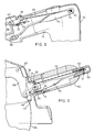
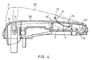
- FIGS 2, 3 and 4 illustrate the handle 52 in more detail.
- the linkage bar 54 is provided with an elongate slot 53, through which passes a pin 51, integral with the push-button 50.
- the existence of the slot 53 provides a small dead movement of the push-button 50 before the linkage bar 54 is actuated.
- a guard lock 34 is pivotally attached to the housing 14 about an axis 36.
- the guard lock 34 is free to move between two limiting positions, a locked position as illustrated and a released position.
- a toe 40 of the guard lock 34 obstructs the guard 66 and prevents it from opening whilst a heel 38 thereof abuts the housing 14.
- the guard lock 34 is biassed towards its released position by a coiled spring 33.
- the guard lock 34 is prevented from adopting its released position under the bias of this spring 33 by means of a flexible cable 30, one end of which is attached to an axis 32 of the guard lock 34, the other end of which is attached to the pin 51 of the push-button 50.
- a leaf-spring 31 biasses the push-button into its elevated position, labelled "a" in Figure 4. Since the leaf-spring 31 is sufficiently strong to overcome the bias of the guard lock spring 33, the guard lock 34 will, at rest, lie in its locked position.
- the spring 31 acts in the same sense on the push-button 50 as does the return spring (not shown) for the guard 66.
- the biassing spring 31 is arranged as illustrated in Figure 4.
- the spring 31 is a leaf-spring, which acts between a shoulder 72 in the push-button 50 and a shoulder 74 in the handle 52.
- the line of action of the leaf-spring 31, that is the line joining the two shoulders 72, 74 passes some distance away from the axis 70 about which the push-button 50 is pivoted.
Landscapes
- Life Sciences & Earth Sciences (AREA)
- Engineering & Computer Science (AREA)
- Mechanical Engineering (AREA)
- Wood Science & Technology (AREA)
- Forests & Forestry (AREA)
- Physics & Mathematics (AREA)
- General Physics & Mathematics (AREA)
- Automation & Control Theory (AREA)
- Sawing (AREA)
Applications Claiming Priority (2)
| Application Number | Priority Date | Filing Date | Title |
|---|---|---|---|
| GB939314155A GB9314155D0 (en) | 1993-07-08 | 1993-07-08 | A guard lock arrangement for a saw |
| GB9314155 | 1993-07-08 |
Publications (1)
| Publication Number | Publication Date |
|---|---|
| EP0633104A1 true EP0633104A1 (de) | 1995-01-11 |
Family
ID=10738499
Family Applications (1)
| Application Number | Title | Priority Date | Filing Date |
|---|---|---|---|
| EP94304878A Withdrawn EP0633104A1 (de) | 1993-07-08 | 1994-07-04 | Pendelschutzhaubenverrastvorrichtung für eine Säge |
Country Status (2)
| Country | Link |
|---|---|
| EP (1) | EP0633104A1 (de) |
| GB (1) | GB9314155D0 (de) |
Cited By (1)
| Publication number | Priority date | Publication date | Assignee | Title |
|---|---|---|---|---|
| US7774942B2 (en) | 2006-10-09 | 2010-08-17 | Pacific Handy Cutter, Inc. | Utility knife |
Citations (3)
| Publication number | Priority date | Publication date | Assignee | Title |
|---|---|---|---|---|
| US4267747A (en) * | 1979-04-26 | 1981-05-19 | Chicago Pneumatic Tool Company | Safety lever |
| DE3236328A1 (de) * | 1981-11-12 | 1983-05-19 | Steyr-Daimler-Puch AG, 1010 Wien | Vorrichtung zum oeffnen der dachluke des fahrer- bzw. fahrgastraumes von kraftfahrzeugen |
| DE4010455C2 (de) * | 1990-03-31 | 1992-01-09 | Elektra-Beckum Lubitz & Co, 4470 Meppen, De |
-
1993
- 1993-07-08 GB GB939314155A patent/GB9314155D0/en active Pending
-
1994
- 1994-07-04 EP EP94304878A patent/EP0633104A1/de not_active Withdrawn
Patent Citations (3)
| Publication number | Priority date | Publication date | Assignee | Title |
|---|---|---|---|---|
| US4267747A (en) * | 1979-04-26 | 1981-05-19 | Chicago Pneumatic Tool Company | Safety lever |
| DE3236328A1 (de) * | 1981-11-12 | 1983-05-19 | Steyr-Daimler-Puch AG, 1010 Wien | Vorrichtung zum oeffnen der dachluke des fahrer- bzw. fahrgastraumes von kraftfahrzeugen |
| DE4010455C2 (de) * | 1990-03-31 | 1992-01-09 | Elektra-Beckum Lubitz & Co, 4470 Meppen, De |
Cited By (2)
| Publication number | Priority date | Publication date | Assignee | Title |
|---|---|---|---|---|
| US7774942B2 (en) | 2006-10-09 | 2010-08-17 | Pacific Handy Cutter, Inc. | Utility knife |
| US8234790B2 (en) | 2006-10-09 | 2012-08-07 | Pacific Handy Cutter, Inc. | Utility knife |
Also Published As
| Publication number | Publication date |
|---|---|
| GB9314155D0 (en) | 1993-08-18 |
Similar Documents
| Publication | Publication Date | Title |
|---|---|---|
| US5752421A (en) | Cutting device with a pivotable cover member for covering and uncovering a cutting portion of a cutting tool | |
| US5129300A (en) | Desk-top type cutter | |
| US5423582A (en) | Power-assist motor-vehicle door latch | |
| US6079106A (en) | Knife blade locking mechanism | |
| US5596808A (en) | Safety for knife-blade lock | |
| TWI326579B (en) | Power working machine | |
| US4693008A (en) | Releasable separate member latching device for a portable hand tool | |
| JPH0730843Y2 (ja) | 引出し回転型扉用ロックハンドル装置 | |
| US4672746A (en) | Protective mechanism for circular saws | |
| US5918522A (en) | Radial arm saw blade guard | |
| US8109545B2 (en) | Lock out mechanism for vehicle door outside handles | |
| US4625406A (en) | Safety device for a portable chain saw | |
| EP1110653B1 (de) | Fensterverriegelungsmechanismus für motorisiertes Werkzeug | |
| EP0906166B1 (de) | Werkzeugeinspannvorrichtung für ein angetriebenes werkzeug | |
| US6758122B2 (en) | Guard and control assembly for a compound miter saw | |
| US11524421B2 (en) | Folding knife | |
| US7175212B2 (en) | Latch having releasable cinching mechanism | |
| US20020134211A1 (en) | Locking arrangement for table saw guard | |
| EP1777046B1 (de) | Trennwerkzeuge | |
| EP0633104A1 (de) | Pendelschutzhaubenverrastvorrichtung für eine Säge | |
| EP0780181B1 (de) | Kappsägeschlitten | |
| US7200941B2 (en) | Chainsaw throttle and brake mechanisms | |
| US7331111B2 (en) | Chainsaw throttle and brake mechanisms | |
| US4716654A (en) | Device for braking the saw chain of a portable power saw | |
| US20080092399A1 (en) | Chainsaw throttle and brake mechanisms |
Legal Events
| Date | Code | Title | Description |
|---|---|---|---|
| PUAI | Public reference made under article 153(3) epc to a published international application that has entered the european phase |
Free format text: ORIGINAL CODE: 0009012 |
|
| AK | Designated contracting states |
Kind code of ref document: A1 Designated state(s): DE GB |
|
| 17P | Request for examination filed |
Effective date: 19950706 |
|
| STAA | Information on the status of an ep patent application or granted ep patent |
Free format text: STATUS: THE APPLICATION IS DEEMED TO BE WITHDRAWN |
|
| 18D | Application deemed to be withdrawn |
Effective date: 19970204 |