EP0633200A1 - Palettenbehälter und Verfahren zu dessen Herstellung - Google Patents
Palettenbehälter und Verfahren zu dessen Herstellung Download PDFInfo
- Publication number
- EP0633200A1 EP0633200A1 EP94109620A EP94109620A EP0633200A1 EP 0633200 A1 EP0633200 A1 EP 0633200A1 EP 94109620 A EP94109620 A EP 94109620A EP 94109620 A EP94109620 A EP 94109620A EP 0633200 A1 EP0633200 A1 EP 0633200A1
- Authority
- EP
- European Patent Office
- Prior art keywords
- casing
- jacket
- inner container
- container
- pallet
- Prior art date
- Legal status (The legal status is an assumption and is not a legal conclusion. Google has not performed a legal analysis and makes no representation as to the accuracy of the status listed.)
- Granted
Links
Images



Classifications
-
- B—PERFORMING OPERATIONS; TRANSPORTING
- B65—CONVEYING; PACKING; STORING; HANDLING THIN OR FILAMENTARY MATERIAL
- B65D—CONTAINERS FOR STORAGE OR TRANSPORT OF ARTICLES OR MATERIALS, e.g. BAGS, BARRELS, BOTTLES, BOXES, CANS, CARTONS, CRATES, DRUMS, JARS, TANKS, HOPPERS, FORWARDING CONTAINERS; ACCESSORIES, CLOSURES, OR FITTINGS THEREFOR; PACKAGING ELEMENTS; PACKAGES
- B65D19/00—Pallets or like platforms, with or without side walls, for supporting loads to be lifted or lowered
- B65D19/02—Rigid pallets with side walls, e.g. box pallets
-
- B—PERFORMING OPERATIONS; TRANSPORTING
- B65—CONVEYING; PACKING; STORING; HANDLING THIN OR FILAMENTARY MATERIAL
- B65D—CONTAINERS FOR STORAGE OR TRANSPORT OF ARTICLES OR MATERIALS, e.g. BAGS, BARRELS, BOTTLES, BOXES, CANS, CARTONS, CRATES, DRUMS, JARS, TANKS, HOPPERS, FORWARDING CONTAINERS; ACCESSORIES, CLOSURES, OR FITTINGS THEREFOR; PACKAGING ELEMENTS; PACKAGES
- B65D77/00—Packages formed by enclosing articles or materials in preformed containers, e.g. boxes, cartons, sacks or bags
- B65D77/04—Articles or materials enclosed in two or more containers disposed one within another
- B65D77/0446—Articles or materials enclosed in two or more containers disposed one within another the inner and outer containers being rigid or semi-rigid and the outer container being of polygonal cross-section not formed by folding or erecting one or more blanks
- B65D77/0453—Articles or materials enclosed in two or more containers disposed one within another the inner and outer containers being rigid or semi-rigid and the outer container being of polygonal cross-section not formed by folding or erecting one or more blanks the inner container having a polygonal cross-section
- B65D77/0466—Articles or materials enclosed in two or more containers disposed one within another the inner and outer containers being rigid or semi-rigid and the outer container being of polygonal cross-section not formed by folding or erecting one or more blanks the inner container having a polygonal cross-section the containers being mounted on a pallet
-
- Y—GENERAL TAGGING OF NEW TECHNOLOGICAL DEVELOPMENTS; GENERAL TAGGING OF CROSS-SECTIONAL TECHNOLOGIES SPANNING OVER SEVERAL SECTIONS OF THE IPC; TECHNICAL SUBJECTS COVERED BY FORMER USPC CROSS-REFERENCE ART COLLECTIONS [XRACs] AND DIGESTS
- Y10—TECHNICAL SUBJECTS COVERED BY FORMER USPC
- Y10T—TECHNICAL SUBJECTS COVERED BY FORMER US CLASSIFICATION
- Y10T29/00—Metal working
- Y10T29/49—Method of mechanical manufacture
- Y10T29/49764—Method of mechanical manufacture with testing or indicating
-
- Y—GENERAL TAGGING OF NEW TECHNOLOGICAL DEVELOPMENTS; GENERAL TAGGING OF CROSS-SECTIONAL TECHNOLOGIES SPANNING OVER SEVERAL SECTIONS OF THE IPC; TECHNICAL SUBJECTS COVERED BY FORMER USPC CROSS-REFERENCE ART COLLECTIONS [XRACs] AND DIGESTS
- Y10—TECHNICAL SUBJECTS COVERED BY FORMER USPC
- Y10T—TECHNICAL SUBJECTS COVERED BY FORMER US CLASSIFICATION
- Y10T29/00—Metal working
- Y10T29/49—Method of mechanical manufacture
- Y10T29/49805—Shaping by direct application of fluent pressure
-
- Y—GENERAL TAGGING OF NEW TECHNOLOGICAL DEVELOPMENTS; GENERAL TAGGING OF CROSS-SECTIONAL TECHNOLOGIES SPANNING OVER SEVERAL SECTIONS OF THE IPC; TECHNICAL SUBJECTS COVERED BY FORMER USPC CROSS-REFERENCE ART COLLECTIONS [XRACs] AND DIGESTS
- Y10—TECHNICAL SUBJECTS COVERED BY FORMER USPC
- Y10T—TECHNICAL SUBJECTS COVERED BY FORMER US CLASSIFICATION
- Y10T29/00—Metal working
- Y10T29/49—Method of mechanical manufacture
- Y10T29/49826—Assembling or joining
- Y10T29/49908—Joining by deforming
- Y10T29/49915—Overedge assembling of seated part
-
- Y—GENERAL TAGGING OF NEW TECHNOLOGICAL DEVELOPMENTS; GENERAL TAGGING OF CROSS-SECTIONAL TECHNOLOGIES SPANNING OVER SEVERAL SECTIONS OF THE IPC; TECHNICAL SUBJECTS COVERED BY FORMER USPC CROSS-REFERENCE ART COLLECTIONS [XRACs] AND DIGESTS
- Y10—TECHNICAL SUBJECTS COVERED BY FORMER USPC
- Y10T—TECHNICAL SUBJECTS COVERED BY FORMER US CLASSIFICATION
- Y10T29/00—Metal working
- Y10T29/49—Method of mechanical manufacture
- Y10T29/49826—Assembling or joining
- Y10T29/49908—Joining by deforming
- Y10T29/49936—Surface interlocking
Definitions
- the invention relates to pallet containers for liquids, with an inner container, each with a closable filling opening and a removal and rinsing opening, and an outer metal lattice casing that rests against the inner container, and a base pan made of sheet metal, designed as a pallet, for positively receiving the inner container and for fastening the lattice casing , wherein the bottom of the inner tub, which is adapted to the bottom of the inner container, has stiffening beads, the bases of which lie in a common, horizontal plane and which form open chambers in the bottom of the tub, the flat bottom tub has a downwardly drawn, outer supporting edge which has one forms hollow support collar, and the floor pan is attached to a pallet frame made of metal, wood or plastic (DE 42 06 945 C1).
- barrier layers on the outside and inside of the plastic inner container caused by fluorination cannot allow liquids such as solvents and solvent-containing liquids to permeate into the plastic prevent so that the cleaning options for the pallet container are limited.
- flammable liquids must not be stored in pallet containers with a plastic inner container, and flammable liquids with a flash point below 0 ° C must not be transported with such containers.
- the inner container has a limited stability against external impact or shock loads.
- the invention has for its object to further develop the generic pallet container with regard to its use for the transport and storage of liquids of all kinds and to show a method for the economical and inexpensive manufacture of the inner container of the pallet container.
- the subclaims contain advantageous and expedient developments of the pallet container.
- the pallet container according to the invention can be used for the transport and storage of liquids which are required in industry for a wide variety of purposes.
- the container can be used for the transport and storage of flammable liquids.
- the container is suitable for use in the food industry due to the fact that it can be completely emptied and that it can be cleaned optimally due to the smooth formation of the inside of the jacket, bottom and lid and the transitions between jacket and bottom part and jacket and lid due to the liquid nests.
- the inner container made of sheet metal, in conjunction with the metal grid jacket, has great stability, which ensures the highest level of security for the pallet container against external impact and impact loads and multiple stackability of the container.
- the economical manufacturing process for the inner container made of sheet metal enables the production of inexpensive pallet containers with high quality.
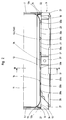
- the pallet container 1 used as a disposable and reusable container according to FIGS. 1 to 3 for the transport and storage of liquid goods of different types has as main components an exchangeable inner container 2 made of sheet metal with a rectangular outline and rounded corners, which has a filler neck 3 which can be closed by a lid 4 with a clamping ring and a further neck 5 in Bottom area is equipped for connection of a tap and flush valve, an outer jacket 6 of intersecting vertical and horizontal bars 7, 8 made of metal and a flat base tray 10 made of sheet metal 9 with Euro-standard length and width dimensions for the positive reception of the inner container 2 .
- the inner container 2 made of sheet metal is welded together from a jacket 11, a bottom part 12 and a cover 13.
- Jacket 11, bottom part 12 and lid 13 of the double-walled inner container 2 consist of a thin inner plate 14 made of corrosion-resistant stainless steel and an outer plate 15 made of mild steel, the thickness of which is greater than that of the inner plate 14 (FIG. 9).
- the inner container 2 can also be designed as a single-walled container.
- the bottom part 12 of the inner container 2 has a drain bottom 16 which runs with a slight slope from the rear edge 12a to the front edge 12b of the bottom part 12 and which also slopes slightly from the two side edges 12c, 12d of the bottom part 12 towards the center of the bottom.
- the bottom 16 of the bottom part 12 of the inner container 2 forms a flat drainage channel 17 which is slightly inclined to the connecting piece 5 in the front edge 12b for connecting a removal and flushing tap, preferably a ball or flap tap.
- the inclined to the drain bottom 16 of the inner container 2, deep-drawn sheet metal material from the bottom tray 10 of the pallet 9 with a drain gutter 17 of the inner container 2 corresponding flat central groove 18 has a downwardly drawn outer support edge 19 and in the direction of and transverse to the central groove 18 Stiffening beads 20a, 20b, the reasons 21 of which lie in a common plane 22-22.
- the stiffening beads 20a, 20b and the central channel 18 form chambers 23 which are open at the bottom in the floor pan 10, and the outer support rim 19 forms a circumferential, hollow support collar 24 on the floor pan 10.
- the floor pan 10 of the pallet 9 designed in this way is characterized by good damping capacity and high rigidity both when subjected to vibrations caused by driving vibrations transmitted by the transport vehicle and from the liquid transport material surge vibrations as well as when subjected to external impact or shock, so that the pallet container 1 meets the high requirements with regard to the required transport and accident safety fully sufficient.
- An all-round outer edge strip 25 is angled from the outer support edge 19 of the floor pan 10 and forms a subframe with a stiffening strut 26 fastened centrally under the floor pan 10.
- the grid jacket 6 fixed by the circumferential support collar 24 of the floor pan 10 of the pallet 9 is supported with the lower, horizontally circumferential grid bar 8 or a lower end profile on the edge strip 25 of the floor pan 10, and the grid jacket 6 is above the lower, horizontal grid bar 8 screwed together with the floor pan 10 and the center 27 and corner feet 28 onto the pallet frame 29 designed as a tubular steel frame.
- the grid jacket 6 is stiffened by an upper frame 30 which is screwed to the grid jacket and protects the inner container 2 from above.
- the modular design of the pallet container allows for a simple and quick assembly of the container, a simple exchange of the inner container made of sheet metal for an inner container made of plastic and a space-saving and cost-effective storage as well as a correspondingly inexpensive transport of the components.
- the drain bottom 16 falls slightly from all edges 12a-12d of the bottom part 12 towards the center, and the bottom 16 has a central removal and rinsing opening 32 with a connection for a removal and rinsing device, wherein the removal opening 32 is assigned a corresponding opening in the bottom of the base trough, the shape of which is adapted to the drain base of the inner container.
- a rectangular sheet-metal cutout (not shown) made of stainless steel and normal steel sheet is bent into a tubular body 33, and its abutting edges 33a, 33b are then longitudinally welded, for example on a frame welding machine (FIG. 5).
- the tubular body 33 is pulled onto a stretching press 34, the expansion jaws 35, 36 of which have the shape of the inner container 2 in the region of its narrow sides (FIG. 6). After the pipe body 33 has been drawn on, the expanding jaws 35, 36 of the stretching press 34 are moved apart by a pressure medium cylinder 37 (FIG. 7). The tubular body 33 assumes the shape of the sheet metal jacket 11. The tubular body 33 is drawn onto the stretching press 34 in such a way that the longitudinal weld seam 38 of the tubular body 33 comes to rest on one of the narrow sides 39 of the sheet metal jacket 11.
- a circumferential bead 40, 41 with a V cross-section is formed in the two end regions of the jacket 11 at a distance from the jacket edges 11a, 11b, e.g. rolled up or pressed in (Fig. 8).
- the two outer edge strips 11c, 11d of the jacket 11 adjoining the beads 40, 41 are cut to size.
- the deep-drawn, trough-shaped bottom part 12 with a beveled edge 42 fits snugly onto or onto the outer flank 40a of the one bead 40 of the jacket 11, and the bottom part 12 is attached to the jacket 11.
- the deep-drawn or pressed cover 13 is then fitted with a bent edge 43 onto or onto the outer flank 41a of the other bead 41 of the casing 11, and the cover 13 is attached to the casing 11.
- Bottom part 12 and cover 13 are welded to the jacket 11 in a liquid-tight manner, preferably welded by roller seams (FIGS. 9 and 10).
- edge strips 11c, 11d of the container casing 11 projecting over the folded edges 42, 43 of the base part 12 and the cover 13 are folded over the folded edge edge 42 and the cover edge 43, and those of the outer flanks 40a, 41a of the beads 40, 41 in Sheath 11 and the edge strips 11c, 11d formed column 44 for receiving the bottom 42 and the lid edge 43 are pressed together; as shown in Fig. 11 for the connection of jacket 11 and bottom part 12.
- annular gaps 45 formed between the jacket 11 and the base part 12 or cover 13 of the inner container 2 are eliminated, which can form liquid pockets in which liquid accumulates during emptying, which form pathogenic germs when the pallet container is used in the food industry can.
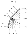
- the inner container 2 is introduced into a support form 46 which is designed such that the inner transition regions 47 between jacket 11 and base part 12 and jacket 11 and cover 13 can expand to a limited extent when the container 2 is subjected to hydraulic or pneumatic pressure , wherein the outwardly projecting outer flanks 40a, 41a of the two beads 40, 41 in the container casing 11 and the edges 42, 43 of the bottom part 12 and the lid 13 which abut against them are clamped from the outside in order to tear open the bottom 48 and to avoid the welded lid seam 49 (FIGS. 12 and 13).
- the increased pressure prevailing in the inner container 2 is expediently used for the leak test of the container.
Landscapes
- Engineering & Computer Science (AREA)
- Mechanical Engineering (AREA)
- Pallets (AREA)
- Auxiliary Devices For And Details Of Packaging Control (AREA)
- Making Paper Articles (AREA)
- Packages (AREA)
- Rigid Containers With Two Or More Constituent Elements (AREA)
- Shaping Metal By Deep-Drawing, Or The Like (AREA)
- Lining Or Joining Of Plastics Or The Like (AREA)
- Supplying Of Containers To The Packaging Station (AREA)
- Containers Having Bodies Formed In One Piece (AREA)
- Food Preservation Except Freezing, Refrigeration, And Drying (AREA)
Abstract
Description
- Die Erfindung betrifft Palettenbehälter für Flüssigkeiten, mit einem Innenbehälter mit je einer verschließbaren Einfüllöffnung und einer Entnahme- und Spülöffnung und einem an dem Innenbehälter anliegenden, äußeren Gittermantel aus Metall sowie einer als Palette ausgebildeten Bodenwanne aus Blech zur formschlüssigen Aufnahme des Innenbehälters und zur Befestigung des Gittermantels, wobei der dem Boden des Innenbehälter angepaßte Boden der Bodenwanne Versteifungssicken aufweist, deren Gründe in einer gemeinsamen, horizontalen Ebene liegen und die in dem Boden der Wanne nach unten offene Kammern bilden, die flache Bodenwanne einen nach unten gezogenen, äußeren Stützrand aufweist, der einen hohlen Stützkragen bildet, und die Bodenwanne auf einem Palettenrahmen aus Metall, Holz oder Kunststoff befestigt ist (DE 42 06 945 C1).
- Die Notwendigkeit zur Einsparung von Rohstoffen und die gesetzlichen Umweltschutzvorschriften zwingen die einschlägige Industrie dazu, Flüssigkeiten zum Transport und zur Lagerung in großvolumigen, auf dem Markt angebotenen, als Mehrwegbehälter ausgebildeten Palettenbehältern der gattungsgemäßen Art anstatt wie bisher in Fässern mit wesentlich geringerem Fassungsvermögen abzufüllen.
- Die wesentlichen Nachteile des gattungsgemäßen Palettenbehälters, die aus der Herstellung des Innenbehälters aus Kunststoff resultieren, sind folgende:
- Die durch Fluorieren bewirkte Ausbildung von Sperrschichten auf der Außen- und Innenseite des Kunststoff-Innenbehälters kann die Permeation von Flüssigkeiten wie Lösungsmitteln und lösungsmittelhaltigen Flüssigkeiten in den Kunststoff nicht unterbinden, so daß die Reinigungsmöglichkeiten für den Palettenbehälter begrenzt sind. Nach den gesetzlichen Bestimmungen dürfen brennbare Flüssigkeiten in Palettenbehältern mit einem Kunststoff-Innenbehälter nicht gelagert werden, und es dürfen mit derartigen Behältern keine brennbaren Flüssigkeiten mit einem Flammpunkt unter 0°C transportiert werden. Schließlich weist der Innenbehälter eine begrenzte Stabilität gegenüber einer äußeren Schlag- bzw. Stoßbeanspruchung auf.
- Der Erfindung liegt die Aufgabe zugrunde, den gattungsgemäßen Palettenbehälter im Hinblick auf dessen Einsatz für den Transport und die Lagerung von Flüssigkeiten aller Art weiterzuentwickeln und ein Verfahren zur wirtschaftlichen und preisgünstigen Herstellung des Innenbehälter des Palettenbehälters aufzuzeigen.
- Diese Aufgabe ist erfindungsgemäß gelöst durch einen Palettenbehälter mit den Merkmalen des Patentanspruchs 1 und das Herstellungsverfahren nach Patentanspruch 6.
- Die Unteransprüche beinhalten vorteilhafte und zweckmäßige Weiterbildungen des Palettenbehälters.
- Der erfindungsgemäße Palettenbehälter ist für den Transport und die Lagerung von Flüssigkeiten, die in der Industrie für die verschiedensten Zwecke benötigt werden, einsetzbar. Insbesondere kann der Behälter für den Transport und die Lagerung von brennbaren Flüssigkeiten verwendet werden. Aufgrund der restlosen Entleerbarkeit und der optimalen Reinigungsmöglichkeit, die durch die Flüssigkeitsnester vermeidende, glatte Ausbildung der Innenseiten von Mantel, Boden und Deckel und der Übergänge zwischen Mantel und Bodenteil sowie Mantel und Deckel bedingt ist, eignet sich der Behälter für eine Verwendung in der Lebensmittelindustrie. Die doppelwandige Konstruktion des Innenbehälters mit Innenblechen aus Edelstahl als Korrosionsschutz und Außenblechen aus Normalstahl, die die Stützfunktion der Seitenwände und des Bodens des Behälters ausüben, erlaubt eine Reduzierung der für korrosionsfeste, einwandige Blechbehälter vorgeschriebenen Wandstärke von 2,5 bis 3 Millimetern um bis zu 50% auf 1,2 bis 1,5 Millimeter. Der Innenbehälter aus Blech weist in Verbindung mit dem Metallgittermantel eine große Stabilität auf, die ein höchstes Maß an Sicherheit des Palettenbehälters gegen äußere Schlag- und Stoßbeanspruchungen und eine mehrfache Stapelbarkeit des Behälters gewährleistet. Das wirtschaftliche Herstellungsverfahren für den Innenbehälter aus Blech ermöglicht eine Fertigung preisgünstiger Palettenbehälter mit hoher Qualität.
- Die Erfindung ist nachstehend anhand von Zeichnungen erläutert. Es zeigt
- Fig. 1
- eine prespektivische Darstellung eines Palettenbehälter mit einem Innenbehälter aus Blech, einem Gittermantel und einer als Bodenwanne ausgebildeten Palette,
- Fig. 2
- einen Längsschnitt und
- Fig. 3
- einen Querschnitt durch den Bodenbereich des Palettenbehälters nach Linie III-III der Fig. 2 in vergrößerter Darstellung,
- Fig. 4
- eine abgeänderte Ausführungsform des Innenbehälters in perspektivischer Darstellung,
- Fign. 5 bis 7
- drei Verfahrensstufen bei der Herstellung des Mantels des Innenbehälters aus Blech,
- FIg. 8
- eine perspektivische Darstellung des mit Sicken zum Anschweißen des Bodenteils und des Deckels versehenen Blechmantels des Innenbehälter,
- Fign. 9 und 10
- die Verbindung des Blechmantels mit dem Bodenteil und dem Deckel aus Blech durch eine Rollennahtschweißung,
- Fig. 11
- die formschlüssige Verbindung des Mantels mit dem Bodenteil,
- Fig. 12
- das Glätten der Übergänge zwischen Mantel und Boden sowie Mantel und Deckel des Innenbehälters durch Aufweiten in einer Stützform und
- Fig. 13
- eine Einzelheit der Stützform im Bereich der Bodenschweißnaht des Innenbehälters nach dem Aufweitvorgang.
- Der als Ein- und Mehrwegbehälter verwendete Palettenbehälter 1 nach den Fign. 1 bis 3 für den Transport und die Lagerung von Flüssiggut unterschiedlicher Art weist als Hauptbauteile einen austauschbaren Innenbehälter 2 aus Blech mit einem rechteckigen Grundriß und abgerundeten Ecken, der mit einem durch einen Deckel 4 mit einem Spannring verschließbaren Einfüllstutzen 3 und mit einem weiteren Stutzen 5 im Bodenbereich zum Anschluß eines Entnahme- und Spülhahns ausgestattet ist, einen Außenmantel 6 aus sich kreuzenden senkrechten und waagrechten Gitterstäben 7, 8 aus Metall sowie eine als flache Bodenwanne 10 aus Blech ausgebildete Palette 9 mit euronormgerechten Längen- und Breitenabmessungen zur formschlüssigen Aufnahme des Innenbehälters 2 auf.
- Der Innenbehälter 2 aus Blech ist aus einem Mantel 11, einem Bodenteil 12 und einem Deckel 13 zusammengeschweißt. Mantel 11, Bodenteil 12 und Deckel 13 des doppelwandig ausgebildeten Innenbehälters 2 bestehen aus einem dünnen Innenblech 14 aus korrosionsfestem Edelstahl und einem Außenblech 15 aus Normalstahl, dessen Stärke größer ist als diejenige des Innenblechs 14 (Fig. 9).
- In Abweichung von der beschriebenen Ausführung kann der Innenbehälter 2 auch als einwandiger Behälter ausgebildet sein.
- Das Bodenteil 12 des Innenbehälters 2 weist einen Ablaufboden 16 auf, der mit einem leichten Gefälle von dem rückwärtigen Rand 12a zum vorderen Rand 12b des Bodenteils 12 verläuft und der außerdem von den beiden Seitenrändern 12c, 12d des Bodenteils 12 leicht zur Bodenmitte hin abfällt. Auf diese Weist bildet der Boden 16 des Bodenteils 12 des Innenbehälters 2 eine flache, zu dem Stutzen 5 in dem vorderen Rand 12b zum Anschluß eines Entnahme- und Spülhahns, vorzugsweise eines Kugel- oder Klappenhahns, leicht geneigte Ablaufrinne 17.
- Die in der Neigung dem Ablaufboden 16 des Innenbehälters 2 angepaßte, aus Blechmaterial tiefgezogene Bodenwanne 10 der Palette 9 mit einer der Ablaufrinne 17 des Innenbehälters 2 entsprechenden flachen Mittelrinne 18 weist einen nach unten gezogenen äußeren Stützrand 19 und in Richtung der und quer zur Mittelrinne 18 verlaufende Versteifungssicken 20a, 20b auf, deren Gründe 21 in einer gemeinsamen Ebene 22-22 liegen. Durch die Versteifungssicken 20a, 20b und die Mittelrinne 18 werden in der Bodenwanne 10 nach unten offene Kammern 23 gebildet, und der äußere Stützrand 19 formt an der Bodenwanne 10 einen umlaufenden, hohlen Stützkragen 24. Die derart gestaltete Bodenwanne 10 der Palette 9 zeichnet sich durch ein gutes Dämpfungsvermögen und eine hohe Steifigkeit sowohl bei einer Schwingungsbeanspruchung durch vom Transportfahrzeug übertragene Fahrschwingungen und von dem flüssigen Transportgut ausgehende Schwallschwingungen als auch bei einer äußeren Schlag- oder Stoßbeanspruchung aus, so daß der Palettenbehälter 1 den hohen Anforderungen hinsichtlich der erforderlichen Transport- und Unfallsicherheit in vollem Umfang genügt.
- Von dem äußeren Stützrand 19 der Bodenwanne 10 ist ein umlaufender äußerer Randstreifen 25 abgewinkelt, der mit einer unter der Bodenwanne 10 mittig befestigten Versteifungsstrebe 26 einen Unterrahmen bildet.
- Der durch den umlaufenden Stützkragen 24 der Bodenwanne 10 der Palette 9 fixierte Gittermantel 6 stützt sich mit dem unteren, waagrecht umlaufenden Gitterstab 8 oder einem unteren Abschlußprofil auf dem Randstreifen 25 der Bodenwanne 10 ab, und der Gittermantel 6 ist über den unteren, waagrechten Gitterstab 8 zusammen mit der Bodenwanne 10 sowie den Mittel- 27 und Eckfüßen 28 auf dem als Stahlrohrrahmen ausgebildeten Palettenrahmen 29 festgeschraubt.
- Der Gittermantel 6 ist durch einen oberen,mit dem Gittermantel verschraubten Rahmen 30 versteift, der den Innenbehälter 2 von oben schützt.
- Die Modulbauweise des Palettenbehälters erlaubt einen einfachen und schnellen Zusammenbau des Behälters, einen einfachen Austausch des Innenbehälters aus Blech gegen einen Innenbehälter aus Kunststoff und eine raumsparende und kostengünstige Lagerung sowie einen enstprechend kostengünstigen Transport der Bauelemente.
- Bei dem Innenbehälter 31 nach Fig. 4 fällt der Ablaufboden 16 von allen Rändern 12a-12d des Bodenteils 12 leicht zur Mitte hin ab, und der Boden 16 weist eine mittige Entnahme- und Spülöffnung 32 mit einem Anschluß für eine Entnahme- und Spülvorrichtung auf, wobei der Entnahmeöffnung 32 eine entsprechende Öffnung im Boden der Bodenwanne zugeordnet ist, dessen Form dem Ablaufboden des Innenbehälters angepaßt ist.
- Zur Herstellung des doppelwandigen Blechmantels 11 des Innenbehälters 2 wird ein nicht dargestellter, reckteckiger Blechausschnitt aus einem Edelstahl- und einem Normalstahlblech zu einem Rohrkörper 33 gebogen, und anschließend werden dessen stoßende Ränder 33a, 33b z.B. auf einer Zargenschweißmaschine längsverscheißt (Fig. 5).
- Der Rohrkörper 33 wird auf eine Reckpresse 34 aufgezogen, deren Spreizbacken 35, 36 die Form des Innenbehälters 2 im Bereich seiner Schmalseiten haben (Fig. 6). Nach dem Aufziehen des Rohrkörpers 33 werden die Spreizbacken 35, 36 der Reckpresse 34 durch einen Druckmittelzylinder 37 auseinandergefahren (Fig. 7). Dabei nimmt der Rohrkörper 33 die Form des Blechmantels 11 an. Der Rohrkörper 33 wird derart auf die Reckpresse 34 aufgezogen, daß die Längsschweißnaht 38 des Rohrkörpers 33 auf eine der Schmalseiten 39 des Blechmantels 11 zu liegen kommt.
- In die beiden Endbereiche des Mantels 11 wird je eine Umfangssicke 40, 41 mit einem V-Querschnitt mit Abstand von den Mantelrändern 11a, 11b eingeformt, z.B. eingerollt oder eingepreßt (Fig. 8).
- Die beiden an die Sicken 40, 41 anschließenden äußeren Randstreifen 11c, 11d des Mantels 11 werden auf Maß beschnitten.
- Anschließend wird das tiefgezogene, wannenförmige Bodenteil 12 mit einem abgekanteten Rand 42 paßgenau auf bzw. an die äußere Flanke 40a der einen Sicke 40 des Mantels 11 auf bzw. angesetzt, und das Bodenteil 12 wird am Mantel 11 angeheftet.
- In gleicher Weise wird danach der tiefgezogene oder gepreßte Deckel 13 mit einem abgekanteten Rand 43 paßgenau auf bzw. an die äußere Flanke 41a der anderen Sicke 41 des Mantels 11 auf- bzw. angesetzt, und der Deckel 13 wird am Mantel 11 angeheftet.
- Bodenteil 12 und Deckel 13 werden mit dem Mantel 11 flüssigkeitsdicht vrschweißt, vorzugsweise rollennahtverschweißt (Fign. 9 und 10).
- Die über die abgekanteten Ränder 42, 43 des Bodenteils 12 und des Deckels 13 vorstehenden Randstreifen 11c, 11d des Behältermantels 11 werden um den abgekanteten Bodenrand 42 und den Deckelrand 43 umgelegt, und die von den äußeren Flanken 40a, 41a der Sicken 40, 41 im Mantel 11 und den Randstreifen 11c, 11d gebildeten Spalte 44 zur Aufnahme des Boden- 42 und des Deckelrandes 43 werden zusammengedrückt; wie dies in Fig. 11 für die Verbindung von Mantel 11 und Bodenteil 12 dargestellt ist.
- In der letzten Stufe des Fertigungsverfahrens werden die zwischen Mantel 11 und Bodenteil 12 bzw. Deckel 13 des Innenbehälters 2 gebildeten Ringspalte 45 beseitigt, die Flüssigkeitsnester bilden können, in denen sich Flüssigkeit beim Entleeren ansammelt, die beim Einsatz des Palettenbehälters in der Lebensmittelindustrie krankheitserregende Keime bilden kann.
- Zur Beseitigung der Ringspalte 45 wird der Innenbehälter 2 in eine Stützform 46 eingebracht, die derart ausgebildet ist, daß sich bei einer hydraulischen oder pneumatischen Druckbeaufschlagung des Behälters 2 die inneren Übergangsbereiche 47 zwischen Mantel 11 und Bodenteil 12 sowie Mantel 11 und Deckel 13 begrenzt aufweiten können, wobei die nach außen vorstehenden äußeren Flanken 40a, 41a der beiden Sicken 40, 41 im Behältermantel 11 und die an diesen anliegenden, abgekanteten Ränder 42, 43 des Bodenteils 12 und des Deckels 13 von außen eingespannt werden, um ein Aufreißen der Boden- 48 und der Deckelschweißnaht 49 zu vermeiden (Fign. 12 u. 13).
- Der in dem Innenbehälter 2 herrschende erhöhte Druck wird zweckmäßig zur Dichtheitsprüfung des Behälters genutzt.
Claims (6)
- Palettenbehälter für Flüssigkeiten, mit einem Innenbehälter mit je einer verschließbaren Einfüllöffnung und einer Entnahme- und Spülöffnung und einem an dem Innenbehälter anliegenden, äußeren Gittermantel aus Metall sowie einer als Palette ausgebildeten Bodenwanne aus Blech zur formschlüssigen Aufnahme des Innenbehälters und zur Befestigung des Gittermantels, wobei der dem Boden des Innenbehälters angepaßte Boden der Bodenwanne Versteifungssicken aufweist, deren Gründe in einer gemeinsamen, horizontalen Ebene liegen und die in dem Boden der Wanne nach unten offene Kammern bilden, die flache Bodenwanne einen nach unten gezogenen, äußeren Stützrand aufweist, der einen hohlen Stützkragen bildet, und die Bodenwanne auf einem Palettenrahmen aus Metall, Holz oder Kunststoff befestigt ist, gekennzeichnet durch einen Innenbehälter (2) aus Blech, der aus einem Mantel (11), einem Bodenteil (12) und einem Deckel (13) zusammengeschweißt ist.
- Palettenbehälter nach Anspruch 1, dadurch gekennzeichnet, daß das Bodenteil (12) des Innenbehältrs (2) einen Ablaufboden (16) aufweist, der mit einem leichten Gefälle von dem rückwärtigen Rand (12a) zum vorderen Rand (12b) des Bodenteils (12) verläuft, an dem ein Stutzen (5) zum Anschluß eines Entnahme- und Spülhahns angeordnet ist.
- Palettenbehälter nach Anspruch 2, dadurch gekennzeichnet, daß der Ablaufboden (16) des Bodenteils (12) ein Gefälle von den beiden Seitenrändern (12c, 12d) zur Bodenmitte hin aufweist und eine mittige, flache Ablaufrinne (17) bildet.
- Palettenbehälter nach Anspruch 1, dadurch gekennzeichnet, daß der Boden (16) des Innenbehälters (31) von allen Rändern (12a-12d) des Bodenteils (12) leicht zur Mitte hin abfällt und eine mittige Entnahme- und Spülöffnung (32) mit einem Anschluß für eine Entnahme- und Spülvorrichtung aufweist, wobei der Entnahmeöffnung (32) eine entsprechende Öffnung im Boden der Bodenwanne zugeordnet ist.
- Palettenbehälter nach einem der Ansprüche 1 bis 4, gekennzeichnet durch eine doppelwandige Ausbildung des Innenbehältrs (2), wobei Mantel (11), Bodenteil (12) und Deckel (13) ein dünnes Innenblech (14) aus korrosionsfestem Edelstahl und ein Außenblech (15) aus Normalstahl mit größerer Stärke als das Innenblech (14) aufweisen.
- Verfahren zur Herstellung des Innenbehälters aus Blech für einen Palettenbehälter nach den Ansprüche 1 bis 5, gekennzeichent durch folgende Verfahrensschritte:a) Biegen eines rechteckigen Blechzuschnittes zu einem Rohrkörper (33);b) Längsverschweißen der stoßenden Ränder (33a, 33b) des Rohrkörpers (33);c) Recken des Rohrkörpers (33) zu einem Mantel (11) mit rechteckigem oder quadratischem Querschnitt;d) Einformen je einer Umfangssicke (40, 41) mit V-Querschnitt in die beiden Endbereiche des Mantels (11) mit Abstand von dessen Rändern (11a, 11b);e) Beschneiden der beiden an die Sicken (40, 41) anschließenden äußeren Randstreifen (11c, 11d) des Mantels (11) auf Maß;f) paßgenaues Aufsetzen bzw. Ansetzen des tiefgezogenen, wannenförmigen Bodenteils (12) mit einem abgekanteten Rand (42) auf bzw. an die äußere Flanke (40a) der einen Sicke (40) des Mantels (11) und Anheften des Bodenteils (12) am Mantel (11);g) paßgenaues Aufsetzen bzw. Ansetzen des Deckels (13) mit einem abgekanteten Rand (43) auf bzw. an die äußere Flanke (41a) der anderen Sicke (41) des Mantels (11) und Anheften des Deckels (13) am Mantel (11);h) flüssigkeitsdichtes Verschweißen von Bodenteil (12) und Deckel (13) mit dem Mantel (11);i) Umlegen der über die abgekanteten Ränder (42, 43) des Bodenteils (12) und des Deckels (13) vorstehenden Randstreifen (11c, 11d) des Behältermantels (11) um den abgekanteten Bodenrand (42) und den Deckelrand (43) und Zusammendrücken der von den äußeren Flanken (40a,41a) der Sicken (40, 41) im Mantel (11) und den Randstreifen (11c, 11d) gebildeten Spalte (44) zur Aufnahme des Boden- (42) und des Deckelrandes (43);j) Aufweiten der inneren Übergangsbereiche (47) zwischen Mantel (11) und Bodenteil (12) sowie Mantel (11) und Deckel (13) des in eine Stützform (46) eingesetzten Behälters (2) zur Beseitigung der zwischen Mantel (11) und Bodenteil (12) sowie Mantel (11) und Deckel (13) gebildeten Ringspalte (45) durch Druckbeaufschlagung des Behälters (2) undk) Dichtheitsprüfung des Behälters (2) unter Innendruck.
Applications Claiming Priority (2)
| Application Number | Priority Date | Filing Date | Title |
|---|---|---|---|
| DE4322375A DE4322375C1 (de) | 1993-07-06 | 1993-07-06 | Verfahren zur Herstellung ein- und doppelwandiger Innenbehälter aus Stahlblech |
| DE4322375 | 1993-07-06 |
Publications (2)
| Publication Number | Publication Date |
|---|---|
| EP0633200A1 true EP0633200A1 (de) | 1995-01-11 |
| EP0633200B1 EP0633200B1 (de) | 1997-09-17 |
Family
ID=6492015
Family Applications (1)
| Application Number | Title | Priority Date | Filing Date |
|---|---|---|---|
| EP94109620A Expired - Lifetime EP0633200B1 (de) | 1993-07-06 | 1994-06-22 | Palettenbehälter und Verfahren zu dessen Herstellung |
Country Status (28)
| Country | Link |
|---|---|
| US (1) | US5499438A (de) |
| EP (1) | EP0633200B1 (de) |
| JP (1) | JP2654475B2 (de) |
| KR (1) | KR950003130A (de) |
| CN (1) | CN1037672C (de) |
| AT (1) | ATE158249T1 (de) |
| AU (1) | AU679060B2 (de) |
| BR (1) | BR9402641A (de) |
| CA (1) | CA2127414C (de) |
| CZ (1) | CZ153094A3 (de) |
| DE (2) | DE4322375C1 (de) |
| DK (1) | DK0633200T3 (de) |
| EE (1) | EE9400131A (de) |
| ES (1) | ES2107088T3 (de) |
| GR (1) | GR3024949T3 (de) |
| HR (1) | HRP940389A2 (de) |
| HU (1) | HU213859B (de) |
| IL (1) | IL110133A (de) |
| LT (1) | LT3477B (de) |
| LV (1) | LV11151B (de) |
| NO (1) | NO306390B1 (de) |
| PL (1) | PL174074B1 (de) |
| RU (1) | RU2086486C1 (de) |
| SI (1) | SI9400268A (de) |
| SK (1) | SK78094A3 (de) |
| TW (1) | TW268925B (de) |
| YU (1) | YU42794A (de) |
| ZA (1) | ZA944707B (de) |
Cited By (6)
| Publication number | Priority date | Publication date | Assignee | Title |
|---|---|---|---|---|
| EP0656299A3 (de) * | 1993-12-04 | 1996-03-20 | Schuetz Werke Gmbh Co Kg | Metallbehälter für den Transport und die Lagerung von Flüssigkeiten. |
| EP1754670A3 (de) * | 2005-08-20 | 2007-11-21 | Protechna S.A. | Transport- und Lagerbehälter für Flüssigkeiten |
| CZ303276B6 (cs) * | 2000-05-25 | 2012-07-11 | Mauser-Werke Gmbh & Co. Kg | Paletový kontejner |
| CN104909080A (zh) * | 2015-06-01 | 2015-09-16 | 无锡四方友信股份有限公司 | 吨包装底板与框架的连接结构 |
| EP4108324A1 (de) * | 2021-06-23 | 2022-12-28 | Jedeau | Sammelbehälter für eine vorrichtung zur entnahme von in-situ-proben aus einer flüssigen ableitung |
| WO2024227581A1 (de) * | 2023-05-02 | 2024-11-07 | Protechna S.A. | Transport- und lagerbehälter für flüssigkeiten |
Families Citing this family (27)
| Publication number | Priority date | Publication date | Assignee | Title |
|---|---|---|---|---|
| DE19642119C2 (de) * | 1996-09-19 | 2000-01-20 | Roth Werke Gmbh | Korb für Palettenbehälter |
| US6803989B2 (en) * | 1997-07-15 | 2004-10-12 | Silverbrook Research Pty Ltd | Image printing apparatus including a microcontroller |
| AT405639B (de) * | 1997-08-06 | 1999-10-25 | Moik Werner | Silo aus holz, insbesondere für die lagerung von rieselfähigem salz |
| DE29800415U1 (de) * | 1998-01-13 | 1998-04-09 | Protechna S.A., Freiburg/Fribourg | Transport- und Lagerbehälter für Flüssigkeiten |
| KR100583091B1 (ko) * | 1998-12-31 | 2006-12-05 | 주식회사 케이씨씨 | 흐름성이 우수한 열경화성 수계수지 조성물 |
| KR100321248B1 (ko) * | 1999-03-10 | 2002-01-19 | 윤종용 | 김치저장고의 운전제어방법 |
| KR100364995B1 (ko) * | 1999-12-08 | 2002-12-16 | 주식회사 엘지이아이 | 김치 냉장고의 김치 숙성 제어 방법 |
| DE20316883U1 (de) * | 2003-10-31 | 2004-03-11 | Protechna S.A. | Palettenartiges Untergestell für Transport- und Lagerbehälter für Flüssigkeiten |
| KR100608011B1 (ko) * | 2004-11-03 | 2006-08-02 | 삼성전자주식회사 | 이미지 표시장치 |
| US10370142B2 (en) * | 2006-06-27 | 2019-08-06 | Stephen P. Palisin, Jr. | Shipping container |
| KR20100009706A (ko) * | 2008-07-21 | 2010-01-29 | 엘지전자 주식회사 | 청소기의 노즐 |
| KR200451689Y1 (ko) * | 2008-07-23 | 2011-01-05 | 주식회사 에이치피티 | 액체 운반 용기 |
| DE102009047075A1 (de) * | 2009-11-24 | 2011-07-14 | Protechna S.A. | Rückschlagventil für Transport- und Lagerbehälter für Flüssigkeiten |
| US9126257B2 (en) | 2011-04-04 | 2015-09-08 | Batesville Services, Inc. | Method of forming sheet metal casket shell |
| DE102011007583B4 (de) | 2011-04-18 | 2015-07-09 | Protechna S.A. | Palettenartiges Untergestell für Transport- und Lagerbehälter für Flüssigkeiten |
| US8789250B2 (en) | 2011-08-05 | 2014-07-29 | Batesville Services, Inc. | Method of forming sheet metal casket shell |
| WO2012100965A1 (de) | 2012-03-14 | 2012-08-02 | Fritz Hakemann | Verfahren zur herstellung eines gastro-behälters und gastro-behälter aus blech |
| CN104097828A (zh) * | 2013-04-12 | 2014-10-15 | 上海舒龙包装材料有限公司 | 一种用于盛装易燃液体的防爆桶及其桶体的加工工艺 |
| CN103817944A (zh) * | 2014-01-22 | 2014-05-28 | 上虞市美思工艺品有限公司 | 含有包边条的杂志盒的制作方法 |
| CN106102951B (zh) * | 2014-02-27 | 2018-02-27 | 东洋制罐集团控股株式会社 | 多边形罐及其成型方法 |
| US9700166B2 (en) * | 2014-12-09 | 2017-07-11 | Architectural Mailboxes, LLC | Impact-resistant mailbox |
| DE102015016814A1 (de) * | 2015-12-23 | 2017-06-29 | Protechna S.A. | Transport- und Lagerbehälter für Flüssigkeiten |
| CN105691972A (zh) * | 2016-04-20 | 2016-06-22 | 无锡四方友信股份有限公司 | 具有外框与底托的桶体结构 |
| DE102017006653B4 (de) * | 2017-07-13 | 2023-10-26 | Mauser-Werke Gmbh | Palettencontainer |
| CN113879717A (zh) * | 2020-07-03 | 2022-01-04 | 蒂尔曼乌肯有限责任公司 | 用于液体或自由流动材料的金属容器 |
| US11717872B2 (en) | 2020-10-07 | 2023-08-08 | United States Of America, As Represented By The Secretary Of The Navy | Stamping device for sheet-metal ammunition tray |
| CN115367293A (zh) * | 2021-05-18 | 2022-11-22 | 无锡德克森包装材料有限公司 | 一种具有密封效果的吨桶结构 |
Citations (3)
| Publication number | Priority date | Publication date | Assignee | Title |
|---|---|---|---|---|
| FR1490718A (fr) * | 1966-06-23 | 1967-08-04 | Andrews Of Aintree Ltd | Perfectionnement aux réservoirs pour le transport des liquides en vrac |
| DE4204010C1 (de) * | 1992-02-12 | 1993-01-14 | Schuetz-Werke Gmbh & Co Kg, 5418 Selters, De | |
| DE4206945C1 (de) * | 1991-03-15 | 1993-03-11 | Schuetz-Werke Gmbh & Co. Kg, 5418 Selters, De |
Family Cites Families (7)
| Publication number | Priority date | Publication date | Assignee | Title |
|---|---|---|---|---|
| GB189705499A (en) * | 1897-03-02 | 1898-03-02 | James Murray | Improvements in Chairs. |
| US1227830A (en) * | 1915-03-31 | 1917-05-29 | Hydraulic Pressed Steel Company | Process of uniting metal bodies. |
| CH620166A5 (de) * | 1976-08-25 | 1980-11-14 | Udo Schuetz | |
| JPH0163630U (de) * | 1987-10-19 | 1989-04-24 | ||
| DE8911915U1 (de) * | 1989-10-06 | 1990-10-31 | Walter Ludwig Behälter- und Stahlbau, 7507 Pfinztal | Doppelwandiger Behälter |
| US5070717A (en) * | 1991-01-22 | 1991-12-10 | General Motors Corporation | Method of forming a tubular member with flange |
| DE9215689U1 (de) * | 1992-11-19 | 1993-03-11 | Gebr. Otto Kg, 57223 Kreuztal | Versorgungs- und Entsorgungsbehälter |
-
1993
- 1993-07-06 DE DE4322375A patent/DE4322375C1/de not_active Expired - Fee Related
-
1994
- 1994-06-21 CZ CZ941530A patent/CZ153094A3/cs unknown
- 1994-06-22 AT AT94109620T patent/ATE158249T1/de not_active IP Right Cessation
- 1994-06-22 DE DE59404074T patent/DE59404074D1/de not_active Expired - Fee Related
- 1994-06-22 ES ES94109620T patent/ES2107088T3/es not_active Expired - Lifetime
- 1994-06-22 EP EP94109620A patent/EP0633200B1/de not_active Expired - Lifetime
- 1994-06-22 DK DK94109620.8T patent/DK0633200T3/da active
- 1994-06-27 IL IL110133A patent/IL110133A/en not_active IP Right Cessation
- 1994-06-28 SK SK780-94A patent/SK78094A3/sk unknown
- 1994-06-30 ZA ZA944707A patent/ZA944707B/xx unknown
- 1994-06-30 SI SI9400268A patent/SI9400268A/sl unknown
- 1994-07-01 RU RU9494022759A patent/RU2086486C1/ru not_active IP Right Cessation
- 1994-07-01 PL PL94304078A patent/PL174074B1/pl not_active IP Right Cessation
- 1994-07-02 KR KR1019940015871A patent/KR950003130A/ko not_active Ceased
- 1994-07-04 HR HRP4322375.3A patent/HRP940389A2/hr not_active Application Discontinuation
- 1994-07-05 YU YU42794A patent/YU42794A/sh unknown
- 1994-07-05 HU HU9402023A patent/HU213859B/hu not_active IP Right Cessation
- 1994-07-05 AU AU66140/94A patent/AU679060B2/en not_active Ceased
- 1994-07-05 BR BR9402641A patent/BR9402641A/pt not_active IP Right Cessation
- 1994-07-05 CA CA002127414A patent/CA2127414C/en not_active Expired - Fee Related
- 1994-07-05 LV LVP-94-138A patent/LV11151B/lv unknown
- 1994-07-05 CN CN94108273A patent/CN1037672C/zh not_active Expired - Fee Related
- 1994-07-05 NO NO942538A patent/NO306390B1/no not_active IP Right Cessation
- 1994-07-06 JP JP6154692A patent/JP2654475B2/ja not_active Expired - Fee Related
- 1994-07-06 US US08/272,387 patent/US5499438A/en not_active Expired - Lifetime
- 1994-07-07 LT LTIP1987A patent/LT3477B/lt not_active IP Right Cessation
- 1994-07-12 TW TW083106300A patent/TW268925B/zh active
- 1994-11-14 EE EE9400131A patent/EE9400131A/xx unknown
-
1997
- 1997-10-08 GR GR970402593T patent/GR3024949T3/el unknown
Patent Citations (3)
| Publication number | Priority date | Publication date | Assignee | Title |
|---|---|---|---|---|
| FR1490718A (fr) * | 1966-06-23 | 1967-08-04 | Andrews Of Aintree Ltd | Perfectionnement aux réservoirs pour le transport des liquides en vrac |
| DE4206945C1 (de) * | 1991-03-15 | 1993-03-11 | Schuetz-Werke Gmbh & Co. Kg, 5418 Selters, De | |
| DE4204010C1 (de) * | 1992-02-12 | 1993-01-14 | Schuetz-Werke Gmbh & Co Kg, 5418 Selters, De |
Cited By (11)
| Publication number | Priority date | Publication date | Assignee | Title |
|---|---|---|---|---|
| EP0656299A3 (de) * | 1993-12-04 | 1996-03-20 | Schuetz Werke Gmbh Co Kg | Metallbehälter für den Transport und die Lagerung von Flüssigkeiten. |
| CZ303276B6 (cs) * | 2000-05-25 | 2012-07-11 | Mauser-Werke Gmbh & Co. Kg | Paletový kontejner |
| EP1754670A3 (de) * | 2005-08-20 | 2007-11-21 | Protechna S.A. | Transport- und Lagerbehälter für Flüssigkeiten |
| AU2006203571B2 (en) * | 2005-08-20 | 2008-07-17 | Protechna S.A. | Transport and storage container for liquids |
| AU2006203571C1 (en) * | 2005-08-20 | 2008-12-11 | Protechna S.A. | Transport and storage container for liquids |
| US8490826B2 (en) | 2005-08-20 | 2013-07-23 | Protechna S.A. | Transport and storage containers for liquids |
| CN104909080A (zh) * | 2015-06-01 | 2015-09-16 | 无锡四方友信股份有限公司 | 吨包装底板与框架的连接结构 |
| EP4108324A1 (de) * | 2021-06-23 | 2022-12-28 | Jedeau | Sammelbehälter für eine vorrichtung zur entnahme von in-situ-proben aus einer flüssigen ableitung |
| FR3124407A1 (fr) * | 2021-06-23 | 2022-12-30 | Jedeau | Bidon de collecte pour dispositif préleveur d'échantillons in-situ d'un effluent liquide |
| WO2024227581A1 (de) * | 2023-05-02 | 2024-11-07 | Protechna S.A. | Transport- und lagerbehälter für flüssigkeiten |
| TWI909420B (zh) * | 2023-05-02 | 2025-12-21 | 瑞士商普洛泰克納公司 | 用於液體運輸及儲存之容器 |
Also Published As
Similar Documents
| Publication | Publication Date | Title |
|---|---|---|
| EP0633200B1 (de) | Palettenbehälter und Verfahren zu dessen Herstellung | |
| EP0656299B1 (de) | Metallbehälter für den Transport und die Lagerung von Flüssigkeiten | |
| DE4117159C2 (de) | Transport- und/oder Lagerbehälter | |
| DE4206945C1 (de) | ||
| DE3819911C2 (de) | ||
| DE4005633C2 (de) | ||
| DE4341539C2 (de) | Behälter für den Transport und die Lagerung von Flüssigkeiten | |
| DE602005006153T2 (de) | Palette zum lagern und transportieren von waren | |
| DE10252745B3 (de) | Lagerbehälter für Flüssigkeiten und Verfahren zur Herstellung des Außenbehälters des Lagerbehälters | |
| WO2014044375A1 (de) | Palettencontainer | |
| DE4108399C1 (de) | ||
| DE9410746U1 (de) | Palettenbehälter | |
| EP1627823A1 (de) | Flüssigkeitsbehälter aus Kunststoff | |
| CH649962A5 (de) | Spundbehaelter. | |
| DE4318966C2 (de) | Palettenbehälter | |
| DE3542709A1 (de) | Verfahren zum herstellen von grossraumbehaeltern sowie dazu verwendbare einzelsegmente und ausrichtewerkzeug zum ausrichten derselben | |
| DE4204010C1 (de) | ||
| DE4425630A1 (de) | Transport- und Lagerbehälter für Flüssigkeiten | |
| DE20218766U1 (de) | Versteifungsblech für den auf Eck- und Mittelfüßen sowie einem Fußrahmen abgestützten Boden eines palettenartigen Untergestells, insbesondere für Palettenbehälter | |
| DE4110847C2 (de) | Stapelbarer Transportbehälter für flüssige und/oder feste Stoffe | |
| DE3816243A1 (de) | Doppelwandige bodenplatte fuer grosscontainer | |
| DE9408485U1 (de) | Mehrweg-Großbehältnis | |
| CH662097A5 (de) | Verformbarer behaelter mit fuellarmatur. | |
| CH639910A5 (en) | Transporting container for liquids, in particular beverages | |
| EP0563808A1 (de) | Behälter und Nachfülleinheit für Flüssigheiten, insbesondere Farbe oder Leim |
Legal Events
| Date | Code | Title | Description |
|---|---|---|---|
| PUAI | Public reference made under article 153(3) epc to a published international application that has entered the european phase |
Free format text: ORIGINAL CODE: 0009012 |
|
| AK | Designated contracting states |
Kind code of ref document: A1 Designated state(s): AT BE CH DE DK ES FR GB GR IE IT LI LU MC NL PT SE |
|
| 17P | Request for examination filed |
Effective date: 19950524 |
|
| RAP1 | Party data changed (applicant data changed or rights of an application transferred) |
Owner name: PROTECHNA S.A. |
|
| 17Q | First examination report despatched |
Effective date: 19960715 |
|
| GRAG | Despatch of communication of intention to grant |
Free format text: ORIGINAL CODE: EPIDOS AGRA |
|
| GRAH | Despatch of communication of intention to grant a patent |
Free format text: ORIGINAL CODE: EPIDOS IGRA |
|
| GRAH | Despatch of communication of intention to grant a patent |
Free format text: ORIGINAL CODE: EPIDOS IGRA |
|
| GRAA | (expected) grant |
Free format text: ORIGINAL CODE: 0009210 |
|
| AK | Designated contracting states |
Kind code of ref document: B1 Designated state(s): AT BE CH DE DK ES FR GB GR IE IT LI LU MC NL PT SE |
|
| PG25 | Lapsed in a contracting state [announced via postgrant information from national office to epo] |
Ref country code: GR Free format text: LAPSE BECAUSE OF FAILURE TO SUBMIT A TRANSLATION OF THE DESCRIPTION OR TO PAY THE FEE WITHIN THE PRESCRIBED TIME-LIMIT Effective date: 19970917 |
|
| REF | Corresponds to: |
Ref document number: 158249 Country of ref document: AT Date of ref document: 19971015 Kind code of ref document: T |
|
| REG | Reference to a national code |
Ref country code: CH Ref legal event code: EP |
|
| GBT | Gb: translation of ep patent filed (gb section 77(6)(a)/1977) |
Effective date: 19970919 |
|
| REG | Reference to a national code |
Ref country code: CH Ref legal event code: NV Representative=s name: PATENTANWAELTE GEORG ROEMPLER UND ALDO ROEMPLER |
|
| REF | Corresponds to: |
Ref document number: 59404074 Country of ref document: DE Date of ref document: 19971023 |
|
| ET | Fr: translation filed | ||
| REG | Reference to a national code |
Ref country code: ES Ref legal event code: FG2A Ref document number: 2107088 Country of ref document: ES Kind code of ref document: T3 |
|
| ITF | It: translation for a ep patent filed | ||
| REG | Reference to a national code |
Ref country code: PT Ref legal event code: SC4A Free format text: AVAILABILITY OF NATIONAL TRANSLATION Effective date: 19970924 Ref country code: GR Ref legal event code: FG4A Free format text: 3024949 |
|
| REG | Reference to a national code |
Ref country code: IE Ref legal event code: FG4D Free format text: 76530 |
|
| REG | Reference to a national code |
Ref country code: DK Ref legal event code: T3 |
|
| PG25 | Lapsed in a contracting state [announced via postgrant information from national office to epo] |
Ref country code: LU Free format text: LAPSE BECAUSE OF NON-PAYMENT OF DUE FEES Effective date: 19980622 Ref country code: IE Free format text: LAPSE BECAUSE OF NON-PAYMENT OF DUE FEES Effective date: 19980622 Ref country code: AT Free format text: LAPSE BECAUSE OF NON-PAYMENT OF DUE FEES Effective date: 19980622 |
|
| PG25 | Lapsed in a contracting state [announced via postgrant information from national office to epo] |
Ref country code: LI Free format text: LAPSE BECAUSE OF NON-PAYMENT OF DUE FEES Effective date: 19980630 Ref country code: CH Free format text: LAPSE BECAUSE OF NON-PAYMENT OF DUE FEES Effective date: 19980630 Ref country code: BE Free format text: LAPSE BECAUSE OF NON-PAYMENT OF DUE FEES Effective date: 19980630 |
|
| PLBE | No opposition filed within time limit |
Free format text: ORIGINAL CODE: 0009261 |
|
| STAA | Information on the status of an ep patent application or granted ep patent |
Free format text: STATUS: NO OPPOSITION FILED WITHIN TIME LIMIT |
|
| 26N | No opposition filed | ||
| BERE | Be: lapsed |
Owner name: S.A. PROTECHNA Effective date: 19980630 |
|
| PG25 | Lapsed in a contracting state [announced via postgrant information from national office to epo] |
Ref country code: PT Free format text: LAPSE BECAUSE OF NON-PAYMENT OF DUE FEES Effective date: 19981231 Ref country code: MC Free format text: LAPSE BECAUSE OF NON-PAYMENT OF DUE FEES Effective date: 19981231 |
|
| PG25 | Lapsed in a contracting state [announced via postgrant information from national office to epo] |
Ref country code: NL Free format text: LAPSE BECAUSE OF NON-PAYMENT OF DUE FEES Effective date: 19990101 |
|
| REG | Reference to a national code |
Ref country code: CH Ref legal event code: PL |
|
| NLV4 | Nl: lapsed or anulled due to non-payment of the annual fee |
Effective date: 19990101 |
|
| REG | Reference to a national code |
Ref country code: PT Ref legal event code: MM4A Free format text: LAPSE DUE TO NON-PAYMENT OF FEES Effective date: 19981231 |
|
| REG | Reference to a national code |
Ref country code: GB Ref legal event code: IF02 |
|
| PGFP | Annual fee paid to national office [announced via postgrant information from national office to epo] |
Ref country code: ES Payment date: 20090604 Year of fee payment: 16 Ref country code: DK Payment date: 20090622 Year of fee payment: 16 |
|
| PGFP | Annual fee paid to national office [announced via postgrant information from national office to epo] |
Ref country code: SE Payment date: 20090625 Year of fee payment: 16 Ref country code: IT Payment date: 20090625 Year of fee payment: 16 |
|
| PGFP | Annual fee paid to national office [announced via postgrant information from national office to epo] |
Ref country code: GB Payment date: 20090617 Year of fee payment: 16 Ref country code: DE Payment date: 20090826 Year of fee payment: 16 |
|
| PGFP | Annual fee paid to national office [announced via postgrant information from national office to epo] |
Ref country code: FR Payment date: 20091119 Year of fee payment: 16 |
|
| REG | Reference to a national code |
Ref country code: DK Ref legal event code: EBP |
|
| EUG | Se: european patent has lapsed | ||
| GBPC | Gb: european patent ceased through non-payment of renewal fee |
Effective date: 20100622 |
|
| REG | Reference to a national code |
Ref country code: FR Ref legal event code: ST Effective date: 20110228 |
|
| PG25 | Lapsed in a contracting state [announced via postgrant information from national office to epo] |
Ref country code: IT Free format text: LAPSE BECAUSE OF NON-PAYMENT OF DUE FEES Effective date: 20100622 |
|
| PG25 | Lapsed in a contracting state [announced via postgrant information from national office to epo] |
Ref country code: DE Free format text: LAPSE BECAUSE OF NON-PAYMENT OF DUE FEES Effective date: 20110101 |
|
| PG25 | Lapsed in a contracting state [announced via postgrant information from national office to epo] |
Ref country code: FR Free format text: LAPSE BECAUSE OF NON-PAYMENT OF DUE FEES Effective date: 20100630 |
|
| REG | Reference to a national code |
Ref country code: ES Ref legal event code: FD2A Effective date: 20110715 |
|
| PG25 | Lapsed in a contracting state [announced via postgrant information from national office to epo] |
Ref country code: GB Free format text: LAPSE BECAUSE OF NON-PAYMENT OF DUE FEES Effective date: 20100622 Ref country code: ES Free format text: LAPSE BECAUSE OF NON-PAYMENT OF DUE FEES Effective date: 20110705 |
|
| PG25 | Lapsed in a contracting state [announced via postgrant information from national office to epo] |
Ref country code: DK Free format text: LAPSE BECAUSE OF NON-PAYMENT OF DUE FEES Effective date: 20100630 |
|
| PG25 | Lapsed in a contracting state [announced via postgrant information from national office to epo] |
Ref country code: ES Free format text: LAPSE BECAUSE OF NON-PAYMENT OF DUE FEES Effective date: 20100623 |
|
| PG25 | Lapsed in a contracting state [announced via postgrant information from national office to epo] |
Ref country code: SE Free format text: LAPSE BECAUSE OF NON-PAYMENT OF DUE FEES Effective date: 20100623 |
|
| REG | Reference to a national code |
Ref country code: GB Ref legal event code: 732E Free format text: REGISTERED BETWEEN 20121011 AND 20121017 |