EP0633352B1 - Stoffauflauf und Verfahren zur Regelung eines Stoffauflaufes - Google Patents
Stoffauflauf und Verfahren zur Regelung eines Stoffauflaufes Download PDFInfo
- Publication number
- EP0633352B1 EP0633352B1 EP94850117A EP94850117A EP0633352B1 EP 0633352 B1 EP0633352 B1 EP 0633352B1 EP 94850117 A EP94850117 A EP 94850117A EP 94850117 A EP94850117 A EP 94850117A EP 0633352 B1 EP0633352 B1 EP 0633352B1
- Authority
- EP
- European Patent Office
- Prior art keywords
- flow
- distributor part
- additional flow
- headbox
- component flows
- Prior art date
- Legal status (The legal status is an assumption and is not a legal conclusion. Google has not performed a legal analysis and makes no representation as to the accuracy of the status listed.)
- Expired - Lifetime
Links
- 230000001105 regulatory effect Effects 0.000 title claims abstract description 39
- 238000000034 method Methods 0.000 title claims abstract description 23
- 239000000725 suspension Substances 0.000 claims abstract description 33
- 238000002156 mixing Methods 0.000 claims abstract description 19
- 230000033228 biological regulation Effects 0.000 abstract description 29
- 239000000835 fiber Substances 0.000 description 26
- XLYOFNOQVPJJNP-UHFFFAOYSA-N water Substances O XLYOFNOQVPJJNP-UHFFFAOYSA-N 0.000 description 7
- 238000007865 diluting Methods 0.000 description 3
- 238000001035 drying Methods 0.000 description 2
- 230000001133 acceleration Effects 0.000 description 1
- 230000015572 biosynthetic process Effects 0.000 description 1
- 210000000481 breast Anatomy 0.000 description 1
- 230000007547 defect Effects 0.000 description 1
- 230000000694 effects Effects 0.000 description 1
- 239000000945 filler Substances 0.000 description 1
- 238000001914 filtration Methods 0.000 description 1
- 230000014759 maintenance of location Effects 0.000 description 1
- 239000000463 material Substances 0.000 description 1
- 239000000203 mixture Substances 0.000 description 1
- 238000005192 partition Methods 0.000 description 1
- 230000000717 retained effect Effects 0.000 description 1
- 239000000126 substance Substances 0.000 description 1
Images






Classifications
-
- D—TEXTILES; PAPER
- D21—PAPER-MAKING; PRODUCTION OF CELLULOSE
- D21F—PAPER-MAKING MACHINES; METHODS OF PRODUCING PAPER THEREON
- D21F1/00—Wet end of machines for making continuous webs of paper
- D21F1/02—Head boxes of Fourdrinier machines
- D21F1/022—Means for injecting material into flow within the headbox
-
- D—TEXTILES; PAPER
- D21—PAPER-MAKING; PRODUCTION OF CELLULOSE
- D21F—PAPER-MAKING MACHINES; METHODS OF PRODUCING PAPER THEREON
- D21F1/00—Wet end of machines for making continuous webs of paper
- D21F1/02—Head boxes of Fourdrinier machines
-
- D—TEXTILES; PAPER
- D21—PAPER-MAKING; PRODUCTION OF CELLULOSE
- D21F—PAPER-MAKING MACHINES; METHODS OF PRODUCING PAPER THEREON
- D21F1/00—Wet end of machines for making continuous webs of paper
- D21F1/02—Head boxes of Fourdrinier machines
- D21F1/026—Details of the turbulence section
-
- D—TEXTILES; PAPER
- D21—PAPER-MAKING; PRODUCTION OF CELLULOSE
- D21F—PAPER-MAKING MACHINES; METHODS OF PRODUCING PAPER THEREON
- D21F1/00—Wet end of machines for making continuous webs of paper
- D21F1/06—Regulating pulp flow
-
- D—TEXTILES; PAPER
- D21—PAPER-MAKING; PRODUCTION OF CELLULOSE
- D21F—PAPER-MAKING MACHINES; METHODS OF PRODUCING PAPER THEREON
- D21F1/00—Wet end of machines for making continuous webs of paper
- D21F1/08—Regulating consistency
Definitions
- the invention concerns a headbox and a method of regulating a headbox of a paper/board machine, by means of which method and headbox it is possible to act upon the grammage profile of the paper reliably across the width of the paper web and favourably also upon the fibre orientation profile in the paper web across the width of the paper web.
- the discharge flow of the pulp suspension out of the headbox must be of uniform velocity in the transverse direction of the paper machine.
- a transverse flow which produces distortion of the fibre orientation, affects the quality factors of the paper produced, such as the dimensional stability of the paper in connection with changes in moisture.
- the main axes of the directional distribution, i.e. orientation, of the fibre mesh in the paper coincide with the directions of the main axes of the paper and that the orientation is symmetric in relation to these axes.
- Said shrinkage profile produces a corresponding change in the transverse grammage profile of the web so that, owing to the shrinkage, the dry grammage profile of a web whose transverse grammage profile was uniform after the press is changed during the drying so that, in both of the lateral areas of the web, the grammage is slightly higher than in the middle area.
- said grammage profile has been regulated by means of the profile bar so that the profile bar of the headbox is kept more open in the middle area than in the lateral areas.
- orientation, of the fibre mesh should coincide with the directions of the main axes of the paper, and the orientation should be symmetric in relation to these axes.
- a change in the orientation is produced as the pulp suspension flow receives components in the transverse direction.
- prior-art methods for the control of the fibre orientation in the paper web, it is, as a rule, possible to control the linear distortion profiles only.
- the prior-art methods are suitable for the control of the fibre orientation, but, when they are used, commonly even a large non-linear residual fault remains in comparison with an even distribution of the orientation.
- the prior-art methods are well suitable for basic regulation of the distortion of the orientation.
- EP-A-462 472 is known, in which the headbox has been divided across its width into compartments by means of partition walls and in which solution, in an individual compartment, there is at least one inlet duct for the passage of a component flow. Moreover, in the solution, in front of the individual inlet duct, a mixer is connected by whose means the pulp suspension ratio can be regulated.
- the mixer comprises a distributor part, by whose means both the throttle, i.e. the flow resistance, of the inlet duct for the first component flow connected with the mixer and the throttle, i.e. the flow resistance, of the flow in the inlet duct for the second component flow connected with the mixer are regulated at the same time.
- the grammage profile is affected by to the pulp flow adding a component flow whose concentration differs from the average concentration of the pulp flow.
- two component flows are introduced into the mixer, and the mixing ratio is regulated continuously so that, when the throttle of the pulp flow or 0-water flow in one component-flow duct is increased, the throttle of the other component flow is reduced, or the other way round.
- the concentration of the overall pulp flow departing from the mixer is affected continuously and, yet, the quantity of said concentration is kept invariable.
- the mixer to the pulp flow, it is possible to add, for example, water alone, 0-water, or a diluted pulp suspension whose concentration and/or chemical composition differ(s) from the concentration of the main pulp flow.
- the pulp suspension that has been regulated in the mixer is passed into the main pulp flow.
- the grammage profile was altered by acting upon the pressure in the discharge duct by means of the profile bar.
- a profile bar is not needed necessarily, because the fibre orientation profile is regulated by means of local component flows passed into different positions of width across the headbox.
- the headbox comprises separate blocks across the width of the headbox, into which blocks it is possible to feed an additional flow, whose consistency has been regulated to the desired level and by means of which additional flow a fault in the grammage profile occurring in a certain width position of the web is corrected.
- an additional flow whose consistency has been regulated to the desired level and by means of which additional flow a fault in the grammage profile occurring in a certain width position of the web is corrected.
- the headbox in accordance with the invention is characterized by the features of the characterizing clause of claim 6.
- Figure 1 illustrates the development of different profiles when proceeding in the machine direction of the paper machine from the turbulence generator.
- Figure 2A is a sectional view of a headbox of a paper machine in accordance with the present patent application.
- Figure 2B is an illustration in the direction K 10 in Fig. 2A.
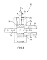
- Figure 3 is a partial illustration of principle of a mixer unit, by whose means a fault in the grammage profile and a fault in the fibre orientation profile can be corrected locally in the direction of width of the web.
- Figure 4A is an illustration of principle of a first position of regulation.
- Figure 4B shows a second position of regulation.
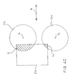
- Figure 4C shows a third position of regulation.
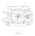
- FIG. 5A shows an embodiment of a mixer unit in accordance with the invention which corresponds to the illustrations of principle in Fig. 3 and in Figs. 4A...4C.
- Fig. 5A is a sectional view of the mixer unit in accordance with the invention.
- Figure 5B is an illustration in the direction K 1 indicated in Fig. 5A.
- Figure 5C is an illustration in the direction K 2 indicated in Fig. 5A.
- Figure 5D is an illustration in the direction K 3 indicated in Fig. 5A.
- Figure 5E is an axonometric view of the distributor part of the mixer unit.
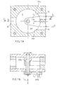
- Figure 6A is a sectional view of an embodiment of a mixer unit, wherein the flow into the inlet chamber of the mixer unit is distributed by means of a separate tumbler piece, which is placed in different closing positions in relation to the inlet openings, in which case, when one inlet opening is being opened, the other inlet opening is closed by the corresponding amount.
- Figure 6B is a sectional view taken along the line I-I in Fig. 6A.
- Figure 7A shows an embodiment of the invention corresponding to Fig. 6A,6B, except that in the embodiment of Figs. 7A,7B the flow quantity of the departing flow Q 3 can also be regulated.
- Fig. 7A is a sectional view of the mixer unit 22.
- Figure 7B is a sectional view taken along the line II-II in Fig. 7A.
- FIG. 1 By means of Fig. 1, the development of different profiles is illustrated when proceeding in the machine direction of the paper machine from the turbulence generator to the forming wire and forwards. In the description related to Fig. 1, reference is made to the different positions illustrated in the figure when moving forwards from the turbulence generator in the direction of flow of the pulp suspension in the paper machine.
- the flow state after the turbulence generator consists of the pressure and thickness profiles. In the embodiments that are used commonly, attempts are made to make these profiles as straight as possible.
- the fibre grammage profile is regulated by profiling the thickness profile of a pulp of uniform consistency, e.g., by means of the profile bar. This, however, produces transverse volumetric flows, which are also seen in the directional profile of the jet, which may partly also arise from the pressure profile of the section A-A.
- the fibre suspension is filtered on the wire part, after which the individual fibres have been bound into the structure of the paper.
- the fibres are oriented in accordance with the difference between the direction and velocity of the jet coming from the headbox and velocity and running direction of the wire (filtered material). In local filtering, there may be differences arising from local variations in retention.
- the paper web shrinks unevenly during drying.
- the fibres and the fillers in the paper move closer to each other, whereby the grammage in the area increases and produces a need to lower the grammage.
- regulation of the grammage profile by means of the profile bar also acts upon the directional profile of the jet.
- Regulation of the thickness profile of the jet could be omitted entirely if the consistency profile after the TG could be regulated independently. In such a case, the jet is run as consistency-profiled and as of uniform thickness into the former. Further, when the pressure profile of the TG can be regulated, the directional-angle profile of the jet can be fine-adjusted separately.
- Fig. 2A shows a headbox as per the invention in connection with a twin-wire former.
- Fig. 2A shows the breast rolls 10 and 11 and the forming wires 12 and 13 running over them, said forming wires defining the forming gap G between them.
- the pulp suspension jet is fed through the slice 15 into the forming gap G defined by the wires 12 and 13.
- the headbox comprises an inlet header 16, a distributor manifold 17, an equalizing chamber 18, a turbulence generator 19, and a discharge duct 14.
- the discharge duct 14 is defined by a stationary lower-lip wall 20 and by an upper-lip wall 21 pivoting around a horizontal articulated joint M.
- the solution of equipment comprises a mixer unit 22, into which a component flow Q 1 is introduced from the inlet header 100.
- a second component flow Q 2 is introduced into the mixer unit 22, which flow is, in the embodiment shown in the figure, the pulp flow coming out of the inlet header 16.
- the flow Q 1 is preferably a diluting flow, whose concentration is, on the whole, different from the average concentration of the pulp suspension.
- the flow Q 1 consists preferably of diluting water.
- the combined flow Q 3 is passed through the throttle point 101 into the distributor pipe 28a and further, out of the distributor pipe, through the throttle point 102, into the turbulence tube 19a 1 of the turbulence generator 19 and further into the discharge duct 14.
- Fig. 2B is a top view of the solution of equipment shown in Fig. 2A, being a partial illustration of principle.
- a diluting flow Q 1.1 ,Q 1.2 ...Q 1.n passes into said units out of the inlet header 100.
- a pulp suspension flow Q 2.1 ,Q 2.2 ...Q 2.n is passed out of the inlet header 16, said flows Q 1 and Q 2 being mixed together in each mixer unit 22a 1 ,22a 2 ... and being thereupon passed into the discharge duct 14.
- each mixer unit 22a 1 ,22a 2 ...22a n specifically in respect of each position of width of the headbox, it is possible to regulate the grammage and the fibre orientation of the web at the particular position of width by means of a flow Q 3.1 ,Q 3.2 ...Q 3.n passed into the pulp suspension. Said regulations are independent from one another.
- Fig. 3 shows a mixer unit 22 in accordance with the invention, by whose means it is possible to supply a pulp flow of desired consistency to a certain position of width of the headbox of the paper machine.
- the mixer unit shown in Fig. 3 it is possible to regulate the grammage profile.
- the mixer unit it is possible to regulate the fibre orientation profile by acting upon the pressure loss in the pulp flow passing through the mixer unit and, thus, upon the velocity of the flow and further upon the flow quantity.
- the mixer unit 22 comprises a first inlet duct 23, through which the component flow Q 1 , preferably a so-called 0-water flow, is introduced into the chamber F of the mixer unit.
- the mixer unit 22 comprises a second duct 24, through which the second component flow Q 2 , which is preferably a component flow at the average concentration of the pulp suspension, is introduced into the chamber F of the mixer unit 22.
- the flows pass, at the consistency ratio distributed by the distributor part 26, through the transverse duct 27 of the distributor part 26, placed in the chamber F, into the outlet duct 25.
- each position of width of the paper machine comprises a separate duct 27a 1 , 27a 2 ..., in front of which there is a mixer unit 22a 1 ,22a 2 ,22a 3 ..., by whose means it is possible to regulate the concentration of the pulp suspension departing from the mixer units, and favourably also the flow velocity of said pulp suspension and, thus, the flow quantity.
- the distributor part 26 can be displaced along a linear path (arrow L 1 ) in the chamber F, and said distributor part 26 can also be rotated (arrow L 2 ) in the chamber F.
- the mouth part 27a of the flow duct 27 extending across the distributor part 26 can be brought into different positions in relation to the end openings 23a,24a of the inlet ducts 23 and 24.
- the flows Q 1 ,Q 2 in the ducts 23 and 24 can be regulated by increasing the throttle, i.e. the flow resistance, of the flow Q 1 in the duct 23 and reducing the throttle, i.e. the flow resistance, of the flow Q 2 in the duct 24, or the other way round.
- the mixing ratio of the flow Q 3 is affected, and rotation of the distributor part 26 affects the pressure loss in the flow Q 3 .
- Fig. 4A is an illustration of principle of a regulation in accordance with the invention.
- the flow has access through the sectional flow areas U 1 and U 2 denoted by the shading into the duct 27 in the distributor part 26.
- the end opening of the duct 23 is denoted with 23a
- the end opening of the duct 24 is denoted with 24a.
- the sectional flow area of the end opening 23a is A 1 , and it corresponds to the sectional flow area of the end opening 24a.
- the shapes of the openings 23a and 24a are similar to one another.
- the central axis of the opening 23a is denoted with X 1
- the central axis of the opening 24a is denoted with X 2 .
- the connecting line of the axes X 1 and X 2 is denoted with Y.
- the orifice of the flow duct 27 in the regulation part 26 is denoted with 27a in the figure.
- the sectional flow area U 1 ,U 2 is increased through which the flow takes place into the duct 27 in the regulation part 26 and (in the way shown in the figure) the distributor part 26 is raised or lowered perpendicularly to the line Y (in the direction N).
- the orifice 27a is displaced in the direction N', which is perpendicular to the direction N.
- the flow openings 23a,24a are arranged in such a way in relation to one another that at least one of the central planes coincide and that at least one central planes perpendicular to said central planes are parallel to one another.
- a solution as shown in the embodiment of Fig. 3 is examined, wherein the distributor part includes a duct 27, but it is obvious that the above examination also applies to the solution of the embodiment shown in Fig. 7, in which the distributor part 260 is a tumbler part, which does not include a separate transverse duct and by means of which tumbler part the end openings 23a,24a of the ducts 23,24 for the component flows are closed and opened.
- the distributor part 26 is shifted to the side (arrow L 2 ), in which case, at the same time, the sectional flow areas U 1 and U 2 are reduced.
- the mixing ratio must remain unchanged. If U 1 was, in the initial situation, larger than U 2 , U 1 is increased by a larger amount than U 2 . In a corresponding way, when the sectional flow areas U 1 and U 2 are reduced, and if U 1 is larger than U 2 , the reduction of U 1 must be greater than the reduction of U 2 .
- the valve solution in accordance with the invention achieves the keeping of the mixing ratio invariable in the regulation of the flow quantity.
- the pressure loss of the flow is affected, and thereby the velocity profile of the flow and further the fibre orientation profile are affected.
- the regulation does not affect the concentration of the flow Q 3 , and thereby the concentration D 3 of the pulp suspension in the overall flow Q 3 flowing out of the duct 25 is kept at its desired regulated value.
- Fig. 5A is a sectional view of a first preferred embodiment of a mixer unit in accordance with the invention, which corresponds to the illustrations in Figs. 3 and 4A...4C.
- the mixer unit 22 comprises a first inlet duct 23 and a second inlet duct 24 as well as an exhaust duct 25.
- the mixer unit comprises a chamber F, in which the distributor part 26 is fitted to be displaceable along a linear path (arrow L 1 ) and in which it is fitted to be rotatable (arrow L 2 ).
- Fig. 5B is an illustration in the direction K 1 indicated in Fig. 5A.
- Fig. 5C is an illustration in the direction K 2 indicated in Fig. 5A.
- Fig. 5D is an illustration in the direction K 3 in Fig. 5A, i.e. from above.
- Fig. 5E is an axonometric illustration of a disassembled distributor part 26 of the mixer unit 22 in accordance with the invention.
- Fig. 6A is a sectional view of an embodiment of a mixer unit 22 falling outside the scope of the claims.
- the distributor part 260 comprises a displacing spindle 260a, by whose means the distributor part 260 can be shifted into different covering positions in relation to the end opening 23a of the first inlet duct 23 and in relation to the end opening 24a of the second inlet duct 24.
- the duct 25 is passed to the desired position of width of the headbox of the paper machine.
- the headbox of the paper machine comprises a number of ducts 25a 1 ,25a 2 ..., which are opened preferably into separate distribution pipes 28a 1 ,28a 2 , each of which passes directly into a turbulence tube 19a 1 ,19a 2 ... of its own placed in the same position of width in the turbulence generator 19.
- Fig. 6B is a sectional view taken along the line II-II in Fig. 6A.
- the spindle 260a is rotated by means of the lever 260b.
- Fig. 7A shows an embodiment of the invention which is in the other respects similar to the embodiment of Figs. 6A and 6B, but in the solution of said embodiment, the flow quantity of the departing flow can also be regulated so that the mixing ratio remains at its regulated invariable value.
- the spindle 260a is displaced along a linear path in the way indicated by the arrow L 5 , in which case the distributor part 260 connected with the spindle is placed in different covering positions in relation to the end openings 23a,24a so that, at the same time, the end openings 23a,24a are closed or opened.
- the regulation of the mixing ratio takes place so that the spindle 260 is rotated (arrow L 4 ), whereby the distributor part 260 is shifted into different covering positions in relation to the end openings 23a,24a, and so that, when the sectional flow area of one end opening is increased, the sectional flow area of the other opening is reduced by the corresponding amount, and the other way round.
- Fig. 7B is a sectional view taken along the line II-II in Fig. 7A.
- the distributor part 260 can be shifted along a linear path, whereby, at the same time, the end openings of the ducts 23 and 24 are opened or closed, in which case the throttle of the outlet flow Q 3 is reduced or increased while the mixing ratio of the flows Q 1 and Q 2 remains at its invariable value.
Landscapes
- Paper (AREA)
- Blow-Moulding Or Thermoforming Of Plastics Or The Like (AREA)
- Crystals, And After-Treatments Of Crystals (AREA)
Claims (10)
- Verfahren zur Regulierung eines Stoffauflaufkastens durch Einführen eines Zusatzflusses (Q3) in die Stoffsuspension an unterschiedlichen Stellen über die Breite des Stoffauflaufkastens hinweg, wobei der Zusatzfluß (Q3) als der Auslaßfluß von einer Mischereinheit (22) vorgesehen wird, in der zwei Komponentenflüsse (Q1, Q2) unterschiedlicher Konzentrationen eingeführt werden, in welchem Verfahren die Konzentration des Zusatzflusses (Q3) regulierbar ist, indem das Mischungsverhältnis der beiden Komponentenflüsse (Q1, Q2) eingestellt wird, ohne die Flußrate des Zusatzflusses (Q3) zu beeinflussen, während die Flußrate des Zusatzflusses (Q3) regulierbar ist, ohne das Mischungsverhältnis der beiden Komponentenflüsse (Q1, Q2) zu beeinflussen,
dadurch gekennzeichnet, daßdie beiden Komponentenflüsse (Q1, Q2) in eine Kammer (F) der Mischereinheit (22) eingeführt werden,die Konzentration und die Flußrate des Zusatzflusses (Q3) mit Hilfe eines in der Kammer (F) verstellbaren Verteilerteiles (26, 260) der Mischereinheit (22) reguliert werden,die Konzentration des Zusatzflusses (Q3) reguliert wird, indem das Verteilerteil (26, 260) derart verstellt wird, daß der Flußwiderstand von einem der beiden in die Kammer (F) eintretenden Komponentenflüsse (Q1, Q2) erhöht wird und der Flußwiderstand des anderen der beiden in die Kammer (F) eintretenden Komponentenflüsse (Q1, Q2) um den entsprechenden Betrag reduziert wird, wodurch das Mischungsverhältnis der beiden Komponentenflüsse (Q1, Q2) eingestellt wird, ohne die Flußrate des Zusatzflusses (Q3) zu beeinflussen, unddie Flußrate des Zusatzflusses (Q3) reguliert wird, indem das Verteilerteil (26, 260) derart verstellt wird, daß die Flußwiderstände der beiden in die Kammer (F) eintretenden Komponentenflüsse (Q1, Q2) gleichzeitig bei einem bestimmten Mischungsverhältnis erhöht oder reduziert werden. - Verfahren nach Anspruch 1,
dadurch gekennzeichnet, daßdie Konzentration und die Flußrate des Zusatzflusses (Q3) reguliert werden, indem das Verteilerteil (26, 260) entlang eines linearen Wegs verschoben wird oder das Verteilerteil (26, 260) mittels einer mit dem Verteilerteil (26, 260) verbundenen Spindel (26a, 260a) gedreht wird. - Verfahren nach einem der vorangegangenen Ansprüche,
dadurch gekennzeichnet, daßdie beiden Komponentenflüsse (Q1, Q2) mit Hilfe zweier Einlaßkanäle (23, 24) in die Kammer (F) gerichtet werden und daß das verwendete Verteilerteil (26) einen Kanal (27) aufweist, der in unterschiedliche Positionen mit Bezug auf die Endöffnungen (23a, 24a) der beiden Einlaßkanäle (23, 24) in die Kammer (F) plazierbar ist. - Verfahren nach Anspruch 3,
dadurch gekennzeichnet, daßdas Verteilerteil (26) in unterschiedliche Abdeckpositionen plazierbar ist, um die Endöffnungen (23a, 24a) zu schließen und zu öffnen. - Verfahren nach Anspruch 1 oder 2,
dadurch gekennzeichnet, daßdie beiden Komponentenflüsse (Q1, Q2) mittels zweier Einlaßkanäle (23, 24) in die Kammer (F) gerichtet werden, daß die Flußrate des Zusatz flusses (Q3) reguliert wird, indem das Verteilerteil (260) entlang eines linearen Wegs in einer Richtung (L5) senkrecht zu der Linie verstellt wird, die die Zentralachsen der Endöffnungen (23a, 24a) der beiden Einlaßkanäle (23, 24) in die Kammer (F) verbindet, und daß die Konzentration des Zusatzflusses (Q3) reguliert wird, indem das Verteilerteil (260) um eine zu der Richtung (L5) des linearen Wegs parallelen Achse gedreht wird. - Stoffauflaufkasten, der reguliert wird, indem ein Zusatzfluß (Q3) in die Stoffsuspension an unterschiedlichen Stellen über die Breite des Stoffauflaufkastens hinweg eingeführt wird, wobei der Stoffauflaufkasten eine Vorrichtung aufweist, mit deren Hilfe die Konzentration des Zusatzflusses (Q3) einstellbar ist, ohne dessen Flußrate zu beeinflussen, und die Flußrate des Zusatzflusses (Q3) einstellbar ist, ohne dessen Konzentration zu beeinflussen, wobei die Vorrichtung eine Mischereinheit (22), einen Auslaßkanal (25) für den Zusatzfluß (Q3) und zwei Einlaßkanäle (23, 24) aufweist, durch welche zwei Komponentenflüsse (Q1, Q2) unterschiedlicher Konzentrationen in die Mischereinheit (22) geleitet werden,
dadurch gekennzeichnet, daßdie Mischereinheit (22) eine Kammer (F) aufweist, in welche die beiden Komponentenflüsse (Q1, Q2) mittels der Einlaßkanäle (23, 24) geleitet werden,die Mischereinheit (22) ferner ein in der Kammer (F) verstellbares Verteilerteil (26, 260) aufweist, welches Verteilerteil (26, 260) mit Bezug auf die Endöffnungen (23a, 24a) der Einlaßkanäle (23, 24) in die Kammer (F) in unterschiedliche Abdeckpositionen bringbar ist, um die Endöffnungen (23a, 24a) zu schließen oder zu öffnen,das Verteilerteil (26, 260) derart ist, daß es so verstellbar ist, daß die Drosselung eines der beiden Komponentenflüsse (Q1, Q2) erhöht wird und die Drosselung des anderen der beiden Komponentenflüsse (Q1, Q2) um den entsprechenden Betrag reduziert wird, wodurch die Konzentration des Zusatzflusses (Q3) einstellbar ist, ohne dessen Flußrate zu beeinflussen, unddas Verteilerteil (26, 260) derart ist, daß es so verstellbar ist, daß die Drosselungen der Komponentenflüsse (Q1, Q2) gleichzeitig erhöht oder reduziert werden, wodurch die Flußrate des Zusatzflusses (Q3) einstellbar ist, ohne das Mischungsverhältnis der beiden Komponentenflüsse (Q1, Q2) zu beeinflussen. - Stoffauflaufkasten nach Anspruch 6,
dadurch gekennzeichnet, daßdas Verteilerteil (26) mit einer Verstellspindel (26a) verbunden ist, mit deren Hilfe das Verteilerteil (26) verstellbar ist. - Stoffauflaufkasten nach Anspruch 6 oder 7,
dadurch gekennzeichnet, daßdas Verteilerteil (26) einen Kanal (27) mit einer Öffnung (27a) aufweist, die mit Bezug auf die Endöffnungen (23a, 24a) in unterschiedliche Positionen bringbar ist, daß die Konzentration des Zusatzflusses (Q3) einstellbar ist durch ein Verstellen des Verteilerteiles (26) entlang eines linearen Wegs, und daß die Flußrate des Zusatzflusses (Q3) durch Drehung des Verteilerteiles (26) einstellbar ist. - Stoffauflaufkasten nach Anspruch 6,
dadurch gekennzeichnet, daßdas Verteilerteil (260) ein verstellbares Schwenkteil ist, das in unterschiedliche Abdeckpositionen mit Bezug auf die Endöffnungen (23a, 24a) bringbar ist. - Stoffauflaufkasten nach Anspruch 9,
dadurch gekennzeichnet, daßdas Verteilerteil (260) mit einer drehbaren Spindel (260a) verbunden ist, die ebenso linear in einer zu ihrer Drehachse parallelen Richtung (L5) verstellbar ist, wodurch durch Drehung der Spindel (260a) das Verteilerteil (260) mit Bezug auf die Endöffnungen (23a, 24a) in unterschiedliche Abdeckpositionen bringbar ist, um die Konzentration des Zusatzflusses (Q3) durch Einstellen der Drosselungen der Komponentenflüsse (Q1, Q2) relativ zueinander zu regulieren, ohne die Flußrate des Zusatzflusses (Q3) zu beeinflussen, und wodurch durch lineares Verstellen der Spindel (260a) das Verteilerteil (260) in unterschiedliche Abdeckpositionen mit Bezug auf die Endöffnungen (23a, 24a) bringbar ist, um die Flußrate des Zusatzflusses (Q3) durch ein gleichzeitiges Erhöhen oder Reduzieren der Drosselungen der Komponentenflüsse (Q1, Q2) zu regulieren, ohne die Konzentration des Zusatzflusses (Q3) zu beeinflussen.
Applications Claiming Priority (2)
| Application Number | Priority Date | Filing Date | Title |
|---|---|---|---|
| FI933029A FI92229C (fi) | 1993-07-01 | 1993-07-01 | Menetelmä ja laite perälaatikon säädössä |
| FI933029 | 1993-07-01 |
Publications (2)
| Publication Number | Publication Date |
|---|---|
| EP0633352A1 EP0633352A1 (de) | 1995-01-11 |
| EP0633352B1 true EP0633352B1 (de) | 1999-01-13 |
Family
ID=8538251
Family Applications (1)
| Application Number | Title | Priority Date | Filing Date |
|---|---|---|---|
| EP94850117A Expired - Lifetime EP0633352B1 (de) | 1993-07-01 | 1994-06-23 | Stoffauflauf und Verfahren zur Regelung eines Stoffauflaufes |
Country Status (6)
| Country | Link |
|---|---|
| US (1) | US5674363A (de) |
| EP (1) | EP0633352B1 (de) |
| AT (1) | ATE175740T1 (de) |
| CA (1) | CA2127155C (de) |
| DE (1) | DE69415879T2 (de) |
| FI (1) | FI92229C (de) |
Cited By (3)
| Publication number | Priority date | Publication date | Assignee | Title |
|---|---|---|---|---|
| WO2011134683A1 (de) | 2010-04-30 | 2011-11-03 | Voith Patent Gmbh | Ventil zum regulieren eines fluidstroms |
| WO2011134681A1 (de) | 2010-04-30 | 2011-11-03 | Voith Patent Gmbh | Ventil zum regulieren eines fluidstroms |
| WO2011134682A1 (de) | 2010-04-30 | 2011-11-03 | Voith Patent Gmbh | Ventil zum regulieren eines fluidstroms |
Families Citing this family (13)
| Publication number | Priority date | Publication date | Assignee | Title |
|---|---|---|---|---|
| US5626722A (en) * | 1995-06-01 | 1997-05-06 | Valmet Corporation | Headbox of a paper/board machine |
| FI115646B (fi) * | 1996-11-26 | 2005-06-15 | Metso Paper Inc | Paperikoneen/kartonkikoneen monikerrosperälaatikko |
| US5833808A (en) * | 1997-01-21 | 1998-11-10 | Beloit Technologies, Inc. | Method of controlling curl employing inline headbox edge flow control valve |
| US6284100B1 (en) | 1997-01-24 | 2001-09-04 | Valmet Corporation | Method and apparatus for controlling a headbox in a paper machine |
| FI100345B (fi) * | 1997-01-24 | 1997-11-14 | Valmet Corp | Menetelmä ja laite paperikoneen perälaatikon säädössä |
| DE19705590A1 (de) * | 1997-02-14 | 1998-08-20 | Voith Sulzer Papiermasch Gmbh | Stoffauflauf einer Papiermaschine |
| US5944957A (en) * | 1997-03-14 | 1999-08-31 | Valmet Corporation | Regulations system in a paper machine for controlling variation of the basis weight of the paper in the machine direction |
| DE19843727A1 (de) * | 1998-09-24 | 2000-03-30 | Voith Sulzer Papiertech Patent | Verfahren und Stoffauflaufsystem zur Verbesserung des Konsistenzquerprofils einer Faserbahn |
| FI112961B (fi) | 1998-11-26 | 2004-02-13 | Metso Paper Inc | Menetelmä ja laite paperikoneen/kartonkikoneen retentioprofiilin mittaamiseksi ja retention hallitsemiseksi |
| DE102004055919A1 (de) * | 2004-11-19 | 2006-05-24 | Voith Paper Patent Gmbh | Stoffauflauf |
| JP4913510B2 (ja) * | 2006-09-05 | 2012-04-11 | 横河電機株式会社 | シミュレーション方法、繊維配向制御方法、及び繊維配向制御装置 |
| US9481777B2 (en) | 2012-03-30 | 2016-11-01 | The Procter & Gamble Company | Method of dewatering in a continuous high internal phase emulsion foam forming process |
| US11441268B2 (en) | 2018-01-05 | 2022-09-13 | International Paper Company | Paper products having increased bending stiffness and cross-direction strength and methods for making the same |
Family Cites Families (11)
| Publication number | Priority date | Publication date | Assignee | Title |
|---|---|---|---|---|
| US4146425A (en) * | 1974-10-02 | 1979-03-27 | Sulzer Brothers Limited | Papermaking machine headbox having a feed channel and an adjacent overflow sump |
| US4640810A (en) * | 1984-06-12 | 1987-02-03 | Scan Web Of North America, Inc. | System for producing an air laid web |
| FI865085A7 (fi) * | 1986-12-12 | 1988-06-13 | Valmet Oy | Infaestningsarrangemang mellan en spetslist och dess reglerspindel vid laeppoeppningen av en inloppslaoda. |
| GB8711330D0 (en) * | 1987-05-14 | 1987-06-17 | Beloit Corp | Headbox |
| FR2631353A1 (fr) * | 1988-05-13 | 1989-11-17 | Semti | Dispositif d'alimentation en melange pateux |
| FI79363C (fi) * | 1988-09-26 | 1989-12-11 | Valmet Paper Machinery Inc | Foerfarande och anordning i inloppslaodan av en pappersmaskin foer att behaerska foerdelningen i pappersbanans fiberorientering. |
| US4879003A (en) * | 1989-04-07 | 1989-11-07 | Process Automation Business, Inc. | Slice lip protector system |
| DE4019593C2 (de) * | 1990-06-20 | 1994-01-20 | Voith Gmbh J M | Stoffauflauf für Papiermaschinen |
| DE4112347C3 (de) * | 1991-04-16 | 2001-01-18 | Voith Gmbh J M | Ventileinrichtung für die Papierindustrie |
| DE4211291C3 (de) * | 1992-04-03 | 2001-06-07 | Voith Gmbh J M | Mischeinrichtung und Verfahren zum Mischen von zwei Flüssigkeiten bei konstantem Gemischvolumenstrom zur Versorgung des Stoffauflaufs einer Papiermaschine |
| DE4323263C2 (de) * | 1993-07-12 | 2001-11-29 | Voith Paper Patent Gmbh | Verfahren zur sektionalen Beeinflussung der Stoffdichte und der Faserorientierung in einem Stoffauflauf einer Papiermaschine und Stoffauflauf zur Durchführung des Verfahrens |
-
1993
- 1993-07-01 FI FI933029A patent/FI92229C/fi not_active IP Right Cessation
-
1994
- 1994-06-23 EP EP94850117A patent/EP0633352B1/de not_active Expired - Lifetime
- 1994-06-23 DE DE69415879T patent/DE69415879T2/de not_active Expired - Fee Related
- 1994-06-23 AT AT94850117T patent/ATE175740T1/de not_active IP Right Cessation
- 1994-06-30 CA CA002127155A patent/CA2127155C/en not_active Expired - Fee Related
- 1994-06-30 US US08/269,345 patent/US5674363A/en not_active Expired - Fee Related
Cited By (6)
| Publication number | Priority date | Publication date | Assignee | Title |
|---|---|---|---|---|
| WO2011134683A1 (de) | 2010-04-30 | 2011-11-03 | Voith Patent Gmbh | Ventil zum regulieren eines fluidstroms |
| WO2011134681A1 (de) | 2010-04-30 | 2011-11-03 | Voith Patent Gmbh | Ventil zum regulieren eines fluidstroms |
| DE102010028403A1 (de) | 2010-04-30 | 2011-11-03 | Voith Patent Gmbh | Ventil zum Regulieren eines Fluidstroms |
| WO2011134682A1 (de) | 2010-04-30 | 2011-11-03 | Voith Patent Gmbh | Ventil zum regulieren eines fluidstroms |
| DE102010028404A1 (de) | 2010-04-30 | 2011-11-03 | Voith Patent Gmbh | Ventil zum Regulieren eines Fluidstroms |
| DE102010028408A1 (de) | 2010-04-30 | 2011-11-03 | Voith Patent Gmbh | Ventil zum Regulieren eines Fluidstroms |
Also Published As
| Publication number | Publication date |
|---|---|
| EP0633352A1 (de) | 1995-01-11 |
| DE69415879D1 (de) | 1999-02-25 |
| DE69415879T2 (de) | 1999-07-29 |
| FI92229C (fi) | 1994-10-10 |
| US5674363A (en) | 1997-10-07 |
| CA2127155C (en) | 1998-11-24 |
| CA2127155A1 (en) | 1995-01-02 |
| FI92229B (fi) | 1994-06-30 |
| FI933029A0 (fi) | 1993-07-01 |
| ATE175740T1 (de) | 1999-01-15 |
Similar Documents
| Publication | Publication Date | Title |
|---|---|---|
| EP0634523B1 (de) | Mehrschichtenstoffauflauf | |
| EP0633352B1 (de) | Stoffauflauf und Verfahren zur Regelung eines Stoffauflaufes | |
| US5674364A (en) | Method and device in the regulation of a headbox | |
| EP0635599B1 (de) | Verfahren und Vorrichtung zur Regelung eines Stoffauflaufkasten | |
| US5843281A (en) | Headbox of a paper machine with edge feed arrangements | |
| US5549792A (en) | Headbox for a paper machine | |
| US5401363A (en) | Method of homogenizing the constitution of a web of paper | |
| US4687548A (en) | Method and apparatus for controlling distortion of fibre orientation in a paper web | |
| JP4571718B2 (ja) | 抄紙機のフローボックスに補助的な材料を調量するための装置及び方法 | |
| JP4546593B2 (ja) | 繊維ウェブの濃度断面プロフィルを改善するための方法および流送箱システム | |
| FI97738B (fi) | Paperi- tai kartonkikoneen perälaatikko | |
| FI93980C (fi) | Menetelmä ja laite perälaatikon säädössä | |
| FI98385C (fi) | Paperi- tai kartonkikoneen perälaatikko | |
| FI92228B (fi) | Menetelmä ja laite perälaatikon säädössä | |
| FI100895B (fi) | Laitteisto paperikoneen/kartonkikoneen perälaatikon yhteydessä laimennusvirtauksen yhdistämisessä jakotukista johdettuun massavirtaukseen | |
| FI92730B (fi) | Menetelmä ja laite perälaatikon säädössä |
Legal Events
| Date | Code | Title | Description |
|---|---|---|---|
| PUAI | Public reference made under article 153(3) epc to a published international application that has entered the european phase |
Free format text: ORIGINAL CODE: 0009012 |
|
| AK | Designated contracting states |
Kind code of ref document: A1 Designated state(s): AT CH DE FR GB IT LI SE |
|
| 17P | Request for examination filed |
Effective date: 19950327 |
|
| 17Q | First examination report despatched |
Effective date: 19960403 |
|
| RAP1 | Party data changed (applicant data changed or rights of an application transferred) |
Owner name: VALMET CORPORATION |
|
| GRAG | Despatch of communication of intention to grant |
Free format text: ORIGINAL CODE: EPIDOS AGRA |
|
| GRAG | Despatch of communication of intention to grant |
Free format text: ORIGINAL CODE: EPIDOS AGRA |
|
| GRAH | Despatch of communication of intention to grant a patent |
Free format text: ORIGINAL CODE: EPIDOS IGRA |
|
| GRAH | Despatch of communication of intention to grant a patent |
Free format text: ORIGINAL CODE: EPIDOS IGRA |
|
| GRAA | (expected) grant |
Free format text: ORIGINAL CODE: 0009210 |
|
| AK | Designated contracting states |
Kind code of ref document: B1 Designated state(s): AT CH DE FR GB IT LI SE |
|
| PG25 | Lapsed in a contracting state [announced via postgrant information from national office to epo] |
Ref country code: LI Free format text: LAPSE BECAUSE OF FAILURE TO SUBMIT A TRANSLATION OF THE DESCRIPTION OR TO PAY THE FEE WITHIN THE PRESCRIBED TIME-LIMIT Effective date: 19990113 Ref country code: CH Free format text: LAPSE BECAUSE OF FAILURE TO SUBMIT A TRANSLATION OF THE DESCRIPTION OR TO PAY THE FEE WITHIN THE PRESCRIBED TIME-LIMIT Effective date: 19990113 |
|
| REF | Corresponds to: |
Ref document number: 175740 Country of ref document: AT Date of ref document: 19990115 Kind code of ref document: T |
|
| REG | Reference to a national code |
Ref country code: CH Ref legal event code: EP |
|
| REF | Corresponds to: |
Ref document number: 69415879 Country of ref document: DE Date of ref document: 19990225 |
|
| ITF | It: translation for a ep patent filed | ||
| ET | Fr: translation filed | ||
| REG | Reference to a national code |
Ref country code: CH Ref legal event code: PL |
|
| PLBE | No opposition filed within time limit |
Free format text: ORIGINAL CODE: 0009261 |
|
| STAA | Information on the status of an ep patent application or granted ep patent |
Free format text: STATUS: NO OPPOSITION FILED WITHIN TIME LIMIT |
|
| 26N | No opposition filed | ||
| EUG | Se: european patent has lapsed | ||
| REG | Reference to a national code |
Ref country code: GB Ref legal event code: IF02 |
|
| PG25 | Lapsed in a contracting state [announced via postgrant information from national office to epo] |
Ref country code: FR Free format text: LAPSE BECAUSE OF NON-PAYMENT OF DUE FEES Effective date: 20020228 |
|
| PGFP | Annual fee paid to national office [announced via postgrant information from national office to epo] |
Ref country code: FR Payment date: 20020611 Year of fee payment: 9 |
|
| PGFP | Annual fee paid to national office [announced via postgrant information from national office to epo] |
Ref country code: SE Payment date: 20060614 Year of fee payment: 13 |
|
| PGFP | Annual fee paid to national office [announced via postgrant information from national office to epo] |
Ref country code: GB Payment date: 20060615 Year of fee payment: 13 |
|
| PGFP | Annual fee paid to national office [announced via postgrant information from national office to epo] |
Ref country code: IT Payment date: 20060630 Year of fee payment: 13 |
|
| EUG | Se: european patent has lapsed | ||
| GBPC | Gb: european patent ceased through non-payment of renewal fee |
Effective date: 20070623 |
|
| PG25 | Lapsed in a contracting state [announced via postgrant information from national office to epo] |
Ref country code: GB Free format text: LAPSE BECAUSE OF NON-PAYMENT OF DUE FEES Effective date: 20070623 |
|
| PG25 | Lapsed in a contracting state [announced via postgrant information from national office to epo] |
Ref country code: SE Free format text: LAPSE BECAUSE OF NON-PAYMENT OF DUE FEES Effective date: 20070624 |
|
| PGFP | Annual fee paid to national office [announced via postgrant information from national office to epo] |
Ref country code: AT Payment date: 20080616 Year of fee payment: 15 |
|
| PGFP | Annual fee paid to national office [announced via postgrant information from national office to epo] |
Ref country code: DE Payment date: 20080620 Year of fee payment: 15 |
|
| PG25 | Lapsed in a contracting state [announced via postgrant information from national office to epo] |
Ref country code: IT Free format text: LAPSE BECAUSE OF NON-PAYMENT OF DUE FEES Effective date: 20070623 |
|
| PG25 | Lapsed in a contracting state [announced via postgrant information from national office to epo] |
Ref country code: DE Free format text: LAPSE BECAUSE OF NON-PAYMENT OF DUE FEES Effective date: 20100101 Ref country code: AT Free format text: LAPSE BECAUSE OF NON-PAYMENT OF DUE FEES Effective date: 20090623 |