EP0633400B2 - Amortisseur de pulsations hydropneumatique adaptif - Google Patents
Amortisseur de pulsations hydropneumatique adaptif Download PDFInfo
- Publication number
- EP0633400B2 EP0633400B2 EP94107744A EP94107744A EP0633400B2 EP 0633400 B2 EP0633400 B2 EP 0633400B2 EP 94107744 A EP94107744 A EP 94107744A EP 94107744 A EP94107744 A EP 94107744A EP 0633400 B2 EP0633400 B2 EP 0633400B2
- Authority
- EP
- European Patent Office
- Prior art keywords
- hydraulic
- pressure
- pulsation damper
- diaphragm
- damper according
- Prior art date
- Legal status (The legal status is an assumption and is not a legal conclusion. Google has not performed a legal analysis and makes no representation as to the accuracy of the status listed.)
- Expired - Lifetime
Links
Images


Classifications
-
- F—MECHANICAL ENGINEERING; LIGHTING; HEATING; WEAPONS; BLASTING
- F15—FLUID-PRESSURE ACTUATORS; HYDRAULICS OR PNEUMATICS IN GENERAL
- F15B—SYSTEMS ACTING BY MEANS OF FLUIDS IN GENERAL; FLUID-PRESSURE ACTUATORS, e.g. SERVOMOTORS; DETAILS OF FLUID-PRESSURE SYSTEMS, NOT OTHERWISE PROVIDED FOR
- F15B1/00—Installations or systems with accumulators; Supply reservoir or sump assemblies
- F15B1/02—Installations or systems with accumulators
- F15B1/04—Accumulators
- F15B1/08—Accumulators using a gas cushion; Gas charging devices; Indicators or floats therefor
-
- F—MECHANICAL ENGINEERING; LIGHTING; HEATING; WEAPONS; BLASTING
- F04—POSITIVE - DISPLACEMENT MACHINES FOR LIQUIDS; PUMPS FOR LIQUIDS OR ELASTIC FLUIDS
- F04B—POSITIVE-DISPLACEMENT MACHINES FOR LIQUIDS; PUMPS
- F04B11/00—Equalisation of pulses, e.g. by use of air vessels; Counteracting cavitation
- F04B11/0008—Equalisation of pulses, e.g. by use of air vessels; Counteracting cavitation using accumulators
- F04B11/0016—Equalisation of pulses, e.g. by use of air vessels; Counteracting cavitation using accumulators with a fluid spring
-
- F—MECHANICAL ENGINEERING; LIGHTING; HEATING; WEAPONS; BLASTING
- F16—ENGINEERING ELEMENTS AND UNITS; GENERAL MEASURES FOR PRODUCING AND MAINTAINING EFFECTIVE FUNCTIONING OF MACHINES OR INSTALLATIONS; THERMAL INSULATION IN GENERAL
- F16L—PIPES; JOINTS OR FITTINGS FOR PIPES; SUPPORTS FOR PIPES, CABLES OR PROTECTIVE TUBING; MEANS FOR THERMAL INSULATION IN GENERAL
- F16L55/00—Devices or appurtenances for use in, or in connection with, pipes or pipe systems
- F16L55/04—Devices damping pulsations or vibrations in fluids
- F16L55/045—Devices damping pulsations or vibrations in fluids specially adapted to prevent or minimise the effects of water hammer
- F16L55/05—Buffers therefor
- F16L55/052—Pneumatic reservoirs
- F16L55/053—Pneumatic reservoirs the gas in the reservoir being separated from the fluid in the pipe
-
- F—MECHANICAL ENGINEERING; LIGHTING; HEATING; WEAPONS; BLASTING
- F15—FLUID-PRESSURE ACTUATORS; HYDRAULICS OR PNEUMATICS IN GENERAL
- F15B—SYSTEMS ACTING BY MEANS OF FLUIDS IN GENERAL; FLUID-PRESSURE ACTUATORS, e.g. SERVOMOTORS; DETAILS OF FLUID-PRESSURE SYSTEMS, NOT OTHERWISE PROVIDED FOR
- F15B2201/00—Accumulators
- F15B2201/20—Accumulator cushioning means
- F15B2201/205—Accumulator cushioning means using gas
-
- F—MECHANICAL ENGINEERING; LIGHTING; HEATING; WEAPONS; BLASTING
- F15—FLUID-PRESSURE ACTUATORS; HYDRAULICS OR PNEUMATICS IN GENERAL
- F15B—SYSTEMS ACTING BY MEANS OF FLUIDS IN GENERAL; FLUID-PRESSURE ACTUATORS, e.g. SERVOMOTORS; DETAILS OF FLUID-PRESSURE SYSTEMS, NOT OTHERWISE PROVIDED FOR
- F15B2201/00—Accumulators
- F15B2201/30—Accumulator separating means
- F15B2201/31—Accumulator separating means having rigid separating means, e.g. pistons
-
- F—MECHANICAL ENGINEERING; LIGHTING; HEATING; WEAPONS; BLASTING
- F15—FLUID-PRESSURE ACTUATORS; HYDRAULICS OR PNEUMATICS IN GENERAL
- F15B—SYSTEMS ACTING BY MEANS OF FLUIDS IN GENERAL; FLUID-PRESSURE ACTUATORS, e.g. SERVOMOTORS; DETAILS OF FLUID-PRESSURE SYSTEMS, NOT OTHERWISE PROVIDED FOR
- F15B2201/00—Accumulators
- F15B2201/30—Accumulator separating means
- F15B2201/315—Accumulator separating means having flexible separating means
- F15B2201/3151—Accumulator separating means having flexible separating means the flexible separating means being diaphragms or membranes
-
- F—MECHANICAL ENGINEERING; LIGHTING; HEATING; WEAPONS; BLASTING
- F15—FLUID-PRESSURE ACTUATORS; HYDRAULICS OR PNEUMATICS IN GENERAL
- F15B—SYSTEMS ACTING BY MEANS OF FLUIDS IN GENERAL; FLUID-PRESSURE ACTUATORS, e.g. SERVOMOTORS; DETAILS OF FLUID-PRESSURE SYSTEMS, NOT OTHERWISE PROVIDED FOR
- F15B2201/00—Accumulators
- F15B2201/30—Accumulator separating means
- F15B2201/315—Accumulator separating means having flexible separating means
- F15B2201/3153—Accumulator separating means having flexible separating means the flexible separating means being bellows
-
- F—MECHANICAL ENGINEERING; LIGHTING; HEATING; WEAPONS; BLASTING
- F15—FLUID-PRESSURE ACTUATORS; HYDRAULICS OR PNEUMATICS IN GENERAL
- F15B—SYSTEMS ACTING BY MEANS OF FLUIDS IN GENERAL; FLUID-PRESSURE ACTUATORS, e.g. SERVOMOTORS; DETAILS OF FLUID-PRESSURE SYSTEMS, NOT OTHERWISE PROVIDED FOR
- F15B2201/00—Accumulators
- F15B2201/30—Accumulator separating means
- F15B2201/32—Accumulator separating means having multiple separating means, e.g. with an auxiliary piston sliding within a main piston, multiple membranes or combinations thereof
-
- F—MECHANICAL ENGINEERING; LIGHTING; HEATING; WEAPONS; BLASTING
- F15—FLUID-PRESSURE ACTUATORS; HYDRAULICS OR PNEUMATICS IN GENERAL
- F15B—SYSTEMS ACTING BY MEANS OF FLUIDS IN GENERAL; FLUID-PRESSURE ACTUATORS, e.g. SERVOMOTORS; DETAILS OF FLUID-PRESSURE SYSTEMS, NOT OTHERWISE PROVIDED FOR
- F15B2201/00—Accumulators
- F15B2201/40—Constructional details of accumulators not otherwise provided for
- F15B2201/41—Liquid ports
- F15B2201/411—Liquid ports having valve means
-
- F—MECHANICAL ENGINEERING; LIGHTING; HEATING; WEAPONS; BLASTING
- F15—FLUID-PRESSURE ACTUATORS; HYDRAULICS OR PNEUMATICS IN GENERAL
- F15B—SYSTEMS ACTING BY MEANS OF FLUIDS IN GENERAL; FLUID-PRESSURE ACTUATORS, e.g. SERVOMOTORS; DETAILS OF FLUID-PRESSURE SYSTEMS, NOT OTHERWISE PROVIDED FOR
- F15B2201/00—Accumulators
- F15B2201/40—Constructional details of accumulators not otherwise provided for
- F15B2201/415—Gas ports
Definitions
- the invention relates to a passive adaptive hydropneumatic Pulsation damper, which for pulsation Hydraulic systems with changing operating pressure, especially hydraulic systems with pulsating working pump, is suitable with the pulsations of the hydraulic medium exposed to gas or Vapor medium, which is connected to the hydraulic system coupled steam or gas-carrying chamber is included and one at the hydraulic Pressure-adaptable, volume-elastic cushion forms.
- the tubular membrane is fluid coupled with two other membranes, both on her facing away from the hose membrane Side of the pressure in the air chamber.
- only one of the other membranes forms part of the wall of this air chamber while the space on the side facing away from the hose membrane Side of the other additional membrane over a longer pressure line connected to the air chamber and over one of these other membrane controlled switching valve with a compressed air source or can be connected to an outlet.
- a pressure accumulator or a membrane expansion vessel known, which essentially consists of a compressed gas chamber exists in which a bellows is arranged, the Interior for receiving hydraulic medium from one hydraulic system communicating with it. This increases with increasing hydraulic pressure Volume of the named bellows, which accordingly absorbs larger amounts of the hydraulic medium and the gas in the compressed gas chamber accordingly compressed.
- the object of the invention is now in a pulsation damper a good one of the type mentioned at the beginning Operating behavior with different hydraulic To ensure operating pressures.
- pulsations effectively dampened, and on the other hand quick changes to the hydraulic work or Operating pressure are made possible.
- this object is achieved by that that formed by the gas or vapor medium volume-elastic cushion over a relatively unthrottled Way which is only the shift of a slight Allows the amount of hydraulic medium, as well as over a throttled path which is the major shift Allows amounts of hydraulic fluid from the pressure of the hydraulic system.
- the invention is based on the general idea the volume-elastic gas or vapor cushion with the hydraulic system via two different ones Coupling ways that differ in terms of their throttling effect extremely differentiate and both trained are that they are just shifting at least in the short term allow small amounts of the hydraulic medium. This ensures that the pulsation damper short-term only small amounts of hydraulic Take up medium from the hydraulic system can, i.e. has a low "swallowing ability". This has the desired consequence that quick changes the operating pressure of the hydraulic system by supply or
- Hydraulic Pressure source and hydraulic consumers can so without further ado "hard” hydraulic be coupled.
- Hydraulic coupling can be volume-elastic Gas or vapor cushion of the invention
- Pulsation damper by appropriate dimensioning its volume is very soft, i.e. a small one Spring rate, as is the case with regard to a effective pulsation damping is desirable.
- a small one Spring rate i.e. a small one Spring rate
- any shift allows large amounts of the hydraulic medium, can always be sufficient in the long term Displacement of hydraulic medium can be ensured, a change to the gas or vapor cushion of the volume to adapt to the mean operating pressure in the hydraulic system.
- the throttled path to adaptation serves of the gas or steam cushion on the hydraulic Working or operating pressure, while the unthrottled Path exclusively to vibrational Coupling between gas or steam cushion and hydraulic system is provided.
- a the amount of unthrottled sliding Hydraulic medium-limiting membrane in the manner of a Barrier between the mobility of the membrane limiting stop surfaces is arranged.
- the movement space of this membrane needs only a little to be larger than that of the Pressure pulsations caused movement amplitudes the membrane.
- the membrane mentioned can on one side of the Gas or vapor medium to be acted upon and accordingly at the same time a lock between the Hydraulic medium and the gas or vapor medium form.
- this membrane like this it is also advantageous to use this membrane like this to arrange that they are on both sides of hydraulic medium is acted upon and two on the throttled path communicating hydraulic areas from each other separates, the one hydraulic area in the gas or steam-carrying chamber is arranged or relative communicates without throttling and the other hydraulic area is arranged in the hydraulic system or so communicated relatively without throttling.
- the throttled Path in a particularly functional design the invention as a throttle opening in said Membrane be formed so that the relatively unthrottled, however only the shift of small quantities of the hydraulic medium path and the relative throttled, but in principle for any quantity of the hydraulic medium constructively open path with each other are united.
- the unrestrictedly displaceable amount of the hydraulic medium delimiting membrane is preferred in arranged a membrane working chamber, the Hydraulic system facing side in series between a hydraulic pressure source, e.g. a pump, and a consumer is arranged, both the Pressure source as well as the consumer a pulsation source can represent.
- a hydraulic pressure source e.g. a pump
- both the Pressure source as well as the consumer a pulsation source can represent.
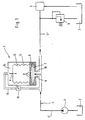
- a pulsating pump for example, a vane pump, on the suction side a reservoir 2 and on the pressure side via a through one Pulsation damper 3 leading pressure line 4 with a Connected consumer 5, from which the supplied Hydraulic medium can flow back to the reservoir 2.
- a pressure relief valve can limit the maximum pressure 6 be present.
- the pulsation damper 3 has a diaphragm working chamber 7, which has a substantially lenticular shape has and by one in the equatorial plane of this Chamber 7 arranged plate-shaped membrane 8 in two Subspaces is divided.
- the lower part of the membrane working chamber 7 forms the hydraulic side of the plate membrane 8 and is with the pump-side part 4 'of the pressure line 4 via a Input channel 9 and with the consumer part 4 '' the pressure line 4 connected via an output channel 10. These channels are close to the central axis of the diaphragm working chamber 7 connected to the same and essentially aligned perpendicular to the plate membrane 8.
- the upper part of the membrane working chamber 7 forms the gas side of the plate membrane 8 and is over to the plate membrane 8 approximately vertical, near the central axis of the Membrane working chamber 7 arranged channels 11 with a Gas space 12 connected, which from a bellows Pressure compensation membrane 13 is enclosed. Over a In Fig. 1 filling line is not shown, if necessary a supply or discharge of pneumatic medium in the or possible from the gas space 12.
- the pressure compensation membrane 13 is inside a chamber 14 arranged, which via a preferably adjustable Throttle 15 provided hydraulic line 16 with the Pressure line 4, in the example shown with the Line part 4 ', is connected.
- the plate membrane 8 normally takes up one position the middle position shown, because over the Line 16 pressure equality in the hydraulic medium of the Pressure line 4 on the one hand and in the hydraulic medium the chamber 14 on the other hand can adjust. In order to are the elastic forces of the plate membrane 8 sufficient, to adjust to the middle position.
- the damping effect is favored in that Input and output channels 9 and 10 perpendicular to Plate membrane 8 are arranged and accordingly in the hydraulic side of the diaphragm working chamber 7 between Input and output channels 9 and 10 a reversal of the Direction of flow of the hydraulic medium takes place, being those associated with the pulsations Pressure waves with strong weakening or extinction from the plate membrane, which is flexibly supported by the gas 12 8 are reflected.
- the compliance of the pulsation damper shown for rapid changes the hydraulic operating pressure in line 4 can be set.
- the greater the throttle resistance the more rigid the hydraulic coupling between Pump 1 and consumer 5.
- the plate membrane 8 temporarily reached an end position and thus becomes immobile because of the throttle 15 still insufficient pressure equalization between the chamber 14 and the pressure line 4 has taken place. So that can Pulsations are temporarily not dampened.
- Each the throttle resistance of the throttle 15 is lower in order pressure equalization between the Chamber 14 and the pressure line 4 take place. Indeed then an increasing softness of the hydraulic Coupling between pump 1 or pressure source and consumer 5 to be accepted. On the other hand, one remains Pulsation damping even with relatively quickly changing hydraulic operating pressures possible.
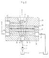
- the membrane working chamber 7 is between two superimposed Plates 17 and 18 formed, which in turn clamped between plate-shaped parts 19 and 20 are.
- the parts 17 and 19 on the one hand and the parts 18 and 20 on the other hand each as a common one-piece Train part.
- the plate 17 and the plate-shaped part 19 have one each coaxial to the central axis of the plate membrane 8 Bore through which the input channel 9 or a connection are formed for the line part 4 'of the pressure line.
- annular groove 21 Concentric to this central bore is on the Plate 17 facing side of the plate-shaped part 19th an annular groove 21 is arranged which communicates with bores, which in the plate-shaped part 19 and in the Plate 17 parallel to those forming the input channel 9 Bores are arranged. This starting from the annular groove 24 On the one hand, holes form the outlet channel 10, which has a corresponding connection hole with the Line part 4 '' of the pressure line 4 is connected. On the other hand is through at least one of these holes Channel 22 formed, which has a corresponding connection hole is connected to the hydraulic line 16, the leads to chamber 14 (see also FIG. 1).
- a connection 23 branches off from the channel 11, via which the quantity of the pneumatic medium in the gas space 12 changed or the gas space 12 can be filled.
- FIG. 3 differs from that 1 shown first in that that a check valve 24 is arranged parallel to the throttle 15 which opens in the direction of the pressure line 4, if there is a faster compared to the pressure in chamber 14 Pressure drop occurs. In this way, a possible Rapidly propagate pressure drop in line 4 to chamber 14. This avoids that the membrane 8 at Pressure drop in line 4 temporarily to that in FIG. 3 create the lower wall of the diaphragm working chamber 7 and have no damping effect can be.
- the membrane 3 forms the output channel 10 of the Membrane working chamber 7 an input channel of a further, similar membrane working chamber 27 with the plate-shaped Diaphragm 28, which faces away from the hydraulic system Side is subjected to the pressure of the atmosphere.
- the output 30 of the membrane working chamber 27 is then with the line part 4 '' of the pressure line 4 connected.
- the another membrane 28 has the following function:
- the gas space 12 have a gas bias pressure if guaranteed is that the gas space 12 at higher operating pressures in Hydraulic system has a sufficient volume.
- This is but synonymous with the fact that the membrane 8 constantly in their lower end position on the lower wall of the diaphragm working chamber 7 rests when the hydraulic pressure in the line 4 drops below the gas bias pressure.
- the membrane 28 is now dimensioned so that it such low pressures a middle layer in the diaphragm working chamber 27 occupies and thus against atmospheric pressure yield in the event of pulsations to reduce damping can.
- the membrane 28 lies on the lower wall the diaphragm working chamber 27 and is ineffective damping.
- FIG. 4 differs from that Embodiments according to FIGS. 1 and 3 essentially in that line 16 is omitted and space 14 ' between the membrane 8 and the membrane 13 with hydraulic Medium is filled, the space 14 'via a throttle opening 15 'communicates in the membrane 8 with the pressure line 4; in addition, the gas space 12 'here is outside the Membrane 13 housed in the pulsation damper 3.
- the line 16 in Figs. 1 and 3rd omit and the chamber 14 with a separate hydraulic Connect pressure source, being by immediate Control of the pressure source and / or by pressure control valves between the separate pressure source and the chamber 14 ensures that the hydraulic pressure in the Chamber 14 corresponds to the hydraulic pressure in the pressure line 4, on the for this purpose a pressure measuring arrangement can be arranged.
- a pressure measuring arrangement can be arranged.
- Such an arrangement can in particular be useful for dual-circuit systems.
- a preferred field of application of the invention is hydraulic Servo systems in motor vehicles, e.g. Power steering, where the pulsation damper on the pressure side of the servo pump also can work effectively when the middle Hydraulic pressure changes.
- Such pressure changes occur e.g. when the steering from the straight ahead position to Stop to the right or left. in the the rest of the pump 1 works in such servo systems regularly with different conveying speeds, because the pump 1 is driven directly by the vehicle engine , whose speed in turn depends on the driving speed and depending on the respective transmission in the drive train is. Even if the pump has a hydraulic flow control combined, certain pressure fluctuations can then occur occur.
Landscapes
- Engineering & Computer Science (AREA)
- General Engineering & Computer Science (AREA)
- Mechanical Engineering (AREA)
- Physics & Mathematics (AREA)
- Fluid Mechanics (AREA)
- Pipe Accessories (AREA)
- Supply Devices, Intensifiers, Converters, And Telemotors (AREA)
- Reciprocating Pumps (AREA)
Claims (18)
- Amortisseur hydropneumatique adaptatif passif de pulsations, convenant pour des systèmes hydrauliques affectés de pulsations et travaillant avec une pression de service variable, notamment des systèmes hydrauliques comportant une pompe travaillant de façon pulsatoire, avec un milieu sous forme de gaz ou de vapeur soumis aux pulsations du fluide hydraulique et qui est renfermé dans une chambre accouplée au système hydraulique et véhiculant la vapeur ou le gaz, et forme un coussin présentant une élasticité de volume, adaptable à la pression hydraulique, caractérisé en ce que le coussin formé par le fluide sous forme de gaz ou de vapeur est chargé par la pression du système hydraulique par l'intermédiaire d'un trajet relativement peu étranglé, qui autorise uniquement le déplacement d'une faible quantité de fluide hydraulique, ainsi que par l'intermédiaire d'un trajet étranglé, qui autorise le déplacement de grandes quantités du fluide hydraulique.
- Amortisseur de pulsations selon la revendication 1, caractérisé en ce que dans le trajet relativement peu étranglé (7,8,11) est disposée une membrane (8) qui limite la quantité du fluide hydraulique déplaçable d'une manière non étranglée et est agencée à la manière d'un système de blocage entre des surfaces de butée limitant la mobilité de la membrane (8).
- Amortisseur de pulsations selon la revendication 2, caractérisé en ce que la membrane (8) est chargée, sur une face, par un fluide à l'état de gaz ou de vapeur.
- Amortisseur de pulsations selon la revendication 2, caractérisé en ce que la membrane (8) est chargée sur ses deux faces par un fluide hydraulique et sépare l'une de l'autre deux zones hydrauliques (14,14') communiquant par l'intermédiaire du trajet étranglé, une zone hydraulique étant disposée dans la chambre (14) véhiculant le gaz ou la vapeur ou bien communiquant avec cette chambre d'une manière relativement non étranglée, et l'autre zone hydraulique étant disposée dans le système hydraulique (4) ou communiquant avec ce dernier d'une manière relativement peu étranglé.
- Amortisseur de pulsations selon la revendication 4, caractérisé en ce que le trajet étranglé est agencé sous la forme d'une ouverture d'étranglement (15') située dans la membrane (8).
- Amortisseur de pulsations selon l'une des revendications 1 à 5, caractérisé en ce qu'en parallèle avec le trajet étranglé est disposée une soupape antiretour (24), qui s'ouvre en direction du système hydraulique (4).
- Amortisseur de pulsations selon l'une des revendications 2 à 6, caractérisé en ce que la membrane (8) est agencée sous la forme d'un disque et est disposée dans le plan équatorial d'un espace de travail (7) de la membrane, essentiellement en forme de lentille et qui forme, d'un côté de la membrane (8), une surface de butée supérieure et, de l'autre côté de la membrane (8), une surface de butée inférieure pour la membrane (8).
- Amortisseur de pulsations selon l'une des revendications 1 à 7, caractérisé en ce que la chambre (14) véhiculant le gaz ou la vapeur est subdivisée par un organe de séparation (13), qui sépare le fluide renfermé en forme de gaz ou de vapeur vis-à-vis du fluide hydraulique et possède une course de soulèvement importante et une mobilité avec une faible résistance dans une zone hydraulique, reliée au système hydraulique (4) au moins par l'intermédiaire du trajet hydraulique étranglé (15,15'), ainsi que dans une zone de gaz ou de vapeur (12,12').
- Amortisseur de pulsations selon la revendication 8, caractérisé en ce que l'élément de séparation (13) est agencé sous la forme d'un soufflet.
- Amortisseur de pulsations selon la revendication 8, caractérisé en ce que l'organe de séparation (13) est agencé sous la forme d'une membrane.
- Amortisseur de pulsations selon la revendication 8, caractérisé en ce que l'organe de séparation (13) est agencé sous la forme d'une vessie.
- Amortisseur de pulsations selon la revendication 8, caractérisé en ce que l'organe de séparation (13) est agencé sous la forme d'un piston.
- Amortisseur de pulsations selon l'une des revendications 1 à 12, caractérisé en ce que le trajet relativement étranglé (15,15') autorise essentiellement seulement des variations de pression, lentes par rapport aux pulsations, dans la chambre (14) véhiculant le gaz ou la vapeur.
- Amortisseur de pulsations selon l'une des revendications 2 à 13, caractérisé en ce que la face, tournée vers le système hydraulique (4), de la membrane (8), qui limite le déplacement du fluide hydraulique, est agencée sous la forme d'une chambre traversée par le fluide hydraulique comportant une entrée (9) et une sortie (10) séparées, l'entrée (9) et la sortie (10) étant traversées de préférence perpendiculairement au plan de la membrane et étant disposées de telle sorte que la direction d'écoulement s'inverse entre l'entrée (9) et la sortie (10).
- Amortisseur de pulsations selon l'une des revendications 1 à 14, caractérisé en ce qu'il est prévu une source de pression séparée pour l'alimentation en pression hydraulique de la chambre (4) véhiculant le gaz ou la vapeur.
- Amortisseur de pulsations selon l'une des revendications 1 à 15, caractérisé en ce que le milieu formé par le gaz ou la vapeur possède une pression de précontrainte.
- Amortisseur de pulsations selon la revendication 16, caractérisé en ce qu'il est prévu un autre amortisseur de pulsations (27,28), qui a un effet d'amortissement essentiellement uniquement au-dessous de la pression de précontrainte et qui peut recevoir seulement de faibles quantités hydrauliques.
- Amortisseur de pulsations selon la revendication 17, caractérisé en ce que l'autre amortisseur de pulsations possède une membrane (28) à déplacement limité, dont une face est chargée par le fluide hydraulique du système hydraulique et dont l'autre face est soumise à la pression atmosphérique ou à une faible pression pneumatique.
Applications Claiming Priority (2)
| Application Number | Priority Date | Filing Date | Title |
|---|---|---|---|
| DE4318553A DE4318553C2 (de) | 1993-06-04 | 1993-06-04 | Adaptiver hydropneumatischer Pulsationsdämpfer |
| DE4318553 | 1993-06-04 |
Publications (4)
| Publication Number | Publication Date |
|---|---|
| EP0633400A2 EP0633400A2 (fr) | 1995-01-11 |
| EP0633400A3 EP0633400A3 (fr) | 1995-03-29 |
| EP0633400B1 EP0633400B1 (fr) | 1996-11-20 |
| EP0633400B2 true EP0633400B2 (fr) | 2000-03-29 |
Family
ID=6489613
Family Applications (1)
| Application Number | Title | Priority Date | Filing Date |
|---|---|---|---|
| EP94107744A Expired - Lifetime EP0633400B2 (fr) | 1993-06-04 | 1994-05-19 | Amortisseur de pulsations hydropneumatique adaptif |
Country Status (3)
| Country | Link |
|---|---|
| US (1) | US5797430A (fr) |
| EP (1) | EP0633400B2 (fr) |
| DE (2) | DE4318553C2 (fr) |
Cited By (1)
| Publication number | Priority date | Publication date | Assignee | Title |
|---|---|---|---|---|
| DE102015202860A1 (de) | 2015-02-17 | 2016-08-18 | Continental Automotive Gmbh | Fluidaktor für haptisch wahrnehmbares Signal an einem Pedal |
Families Citing this family (74)
| Publication number | Priority date | Publication date | Assignee | Title |
|---|---|---|---|---|
| DE4318553C2 (de) * | 1993-06-04 | 1995-05-18 | Daimler Benz Ag | Adaptiver hydropneumatischer Pulsationsdämpfer |
| FR2739170B1 (fr) * | 1995-09-25 | 1997-12-12 | Roche Emile | Reservoir hydropneumatique anti-belier avec dispositif d'admission et de regulation d'air, procede d'admission d'air |
| DE19700633B4 (de) * | 1997-01-10 | 2005-06-02 | Voith Sulzer Papiermaschinen Gmbh | Vorrichtung zum Auftragen eines flüssigen oder pastösen Mediums auf eine laufende Materialbahn, vorzugsweise aus Papier oder Karton, und Maschine zur Papier- oder Kartonherstellung |
| DE19706427A1 (de) * | 1997-02-19 | 1998-08-20 | Itt Mfg Enterprises Inc | Druckmittelspeicher |
| JPH11280598A (ja) * | 1998-03-31 | 1999-10-12 | Mitsubishi Electric Corp | 高圧アキュムレータのダイヤフラムストッパ構造 |
| JP3696729B2 (ja) * | 1998-04-15 | 2005-09-21 | 三菱電機株式会社 | 高圧アキュムレータ |
| JP2000108189A (ja) * | 1998-10-09 | 2000-04-18 | Husky Injection Molding Syst Ltd | 振動減衰装置、振動減衰方法、及び油圧射出成形装置 |
| DE19920852A1 (de) * | 1999-05-06 | 2000-11-16 | Continental Teves Ag & Co Ohg | Schwingungsdämpfungseinrichtung |
| GB9920212D0 (en) * | 1999-08-27 | 1999-10-27 | Binks Ltd | Surge suppression apparatus |
| EP0971164A3 (fr) | 1999-09-06 | 2000-04-05 | Dobson Industries Corp. | Dispositif de réduction de pulsations de pression dans des conduits hydrauliques |
| DE19945220A1 (de) * | 1999-09-21 | 2001-03-22 | Mann & Hummel Filter | Einrichtung zur Dämpfung von Druckstößen |
| JP2002013501A (ja) * | 2000-06-30 | 2002-01-18 | Nok Corp | アキュムレータ |
| US6491289B1 (en) * | 2000-11-14 | 2002-12-10 | Elyakim Schaap | Oleo-pneumatic shock absorbing system |
| DE10057746A1 (de) * | 2000-11-16 | 2002-06-06 | Hydac Technology Gmbh | Hydrospeicher |
| SE518301C2 (sv) * | 2001-02-13 | 2002-09-24 | Tetra Laval Holdings & Finance | Dämpningsanordning för en kolvpump |
| DE10112618A1 (de) * | 2001-03-14 | 2002-09-19 | Bosch Gmbh Robert | Kolbenpumpe |
| US6439266B1 (en) | 2001-05-01 | 2002-08-27 | American Air Liquide, Inc. | Pressure pulsation damping valve |
| EP1256755A1 (fr) * | 2001-05-11 | 2002-11-13 | Dobson Industries Corp. | Dispositif de réduction des oscillations de pression dans les conduits hydrauliques |
| DE10148220A1 (de) * | 2001-09-28 | 2003-04-17 | Bosch Gmbh Robert | Vorrichtung zum Dämpfen von Druckpulsationen in einem Fluidsystem, insbesondere in einem Kraftstoffsystem einer Brennkraftmaschine, sowie Kraftstoffsystem |
| DE10215846A1 (de) * | 2002-04-10 | 2003-11-06 | Hydac Technology Gmbh | Hydrospeicher, insbesondere Membranspeicher |
| US6986640B2 (en) * | 2002-05-20 | 2006-01-17 | Oliver Laing | Motor pump with expansion tank |
| RU2215926C1 (ru) * | 2002-12-18 | 2003-11-10 | Левченко Евгений Леонидович | Демпфер сглаживающий пневмогидравлический |
| DE10313418B3 (de) * | 2003-03-25 | 2004-11-18 | Daimlerchrysler Ag | Pulsationsdämpfungseinrichtung |
| DE10317854A1 (de) * | 2003-04-16 | 2004-11-04 | Volkswagen Ag | Druckspeicher einer hydraulischen Steuerungsvorrichtung und Verfahren zur Erhöhung der Betriebssicherheit eines Druckspeichers |
| FR2863316B1 (fr) * | 2003-12-04 | 2007-12-28 | Renault Sas | Dispositif d'amortissement d'ondes de pression dans une conduite et installation d'injection de carburant equipee d'un tel dispositif |
| DE102004008299A1 (de) * | 2004-02-20 | 2005-09-01 | Daimlerchrysler Ag | Brennkraftmaschine mit einem Schmiermittelkreislauf und einem Dämpfungselement |
| JP4641387B2 (ja) * | 2004-06-01 | 2011-03-02 | 日産自動車株式会社 | 流体継手 |
| US20070056649A1 (en) * | 2005-09-09 | 2007-03-15 | Chang Hsu P | Pressure container with replaceable bellows |
| US8303894B2 (en) * | 2005-10-13 | 2012-11-06 | Accuri Cytometers, Inc. | Detection and fluidic system of a flow cytometer |
| US8017402B2 (en) | 2006-03-08 | 2011-09-13 | Accuri Cytometers, Inc. | Fluidic system for a flow cytometer |
| US7857005B2 (en) * | 2005-12-07 | 2010-12-28 | Accuri Cytometers, Inc. | Pulsation attenuator for a fluidic system |
| JP2007187099A (ja) * | 2006-01-13 | 2007-07-26 | Toyota Motor Corp | 燃料配管の防振構造 |
| US8283177B2 (en) * | 2006-03-08 | 2012-10-09 | Accuri Cytometers, Inc. | Fluidic system with washing capabilities for a flow cytometer |
| US7780916B2 (en) * | 2006-03-08 | 2010-08-24 | Accuri Cytometers, Inc. | Flow cytometer system with unclogging feature |
| US7981661B2 (en) * | 2006-04-17 | 2011-07-19 | Accuri Cytometers, Inc. | Flow cytometer system with sheath and waste fluid measurement |
| DE102006019672B4 (de) * | 2006-04-27 | 2013-11-14 | Robert Bosch Gmbh | Hydraulikfluidspeicher mit integrierter Hochdruck- und Niederdruckkammer |
| US8715573B2 (en) * | 2006-10-13 | 2014-05-06 | Accuri Cytometers, Inc. | Fluidic system for a flow cytometer with temporal processing |
| WO2008058217A2 (fr) * | 2006-11-07 | 2008-05-15 | Accuri Instruments Inc. | Cuve de circulation pour système de cytométrie en flux |
| TW200905080A (en) * | 2007-06-08 | 2009-02-01 | Sequal Technologies Inc | Diaphragm muffler and method of use |
| FR2919356B1 (fr) * | 2007-07-26 | 2009-10-30 | Suntec Ind France Soc Par Acti | Pompe modulante a liquide |
| US8432541B2 (en) * | 2007-12-17 | 2013-04-30 | Accuri Cytometers, Inc. | Optical system for a flow cytometer with an interrogation zone |
| EP2113661B1 (fr) * | 2008-04-29 | 2010-10-27 | MAT Mischanlagentechnik GmbH | Amortisseur de pulsations pour flux d'acheminement pulsés |
| EP2169690B1 (fr) * | 2008-09-24 | 2012-08-29 | ABB Technology AG | Compensateur de pression |
| US8171959B2 (en) * | 2008-12-22 | 2012-05-08 | Spx Apv Danmark A/S | Dampener apparatus and method |
| US8507279B2 (en) * | 2009-06-02 | 2013-08-13 | Accuri Cytometers, Inc. | System and method of verification of a prepared sample for a flow cytometer |
| US20110061471A1 (en) * | 2009-06-02 | 2011-03-17 | Rich Collin A | System and method of verification of a sample for a flow cytometer |
| US9551600B2 (en) | 2010-06-14 | 2017-01-24 | Accuri Cytometers, Inc. | System and method for creating a flow cytometer network |
| WO2012061155A2 (fr) | 2010-10-25 | 2012-05-10 | Accuri Cytometers, Inc. | Systèmes et interface utilisateur pour collecter un ensemble de données dans un cytomètre de flux |
| DE102010062693A1 (de) * | 2010-12-09 | 2012-06-14 | Robert Bosch Gmbh | Hydrospeichereinrichtung |
| GB201108917D0 (en) | 2011-05-27 | 2011-07-13 | Rolls Royce Plc | A Hydraulic damping apparatus |
| DE102011115849B3 (de) * | 2011-10-13 | 2012-05-10 | Thomas Magnete Gmbh | Vorrichtung zum Dosieren und Zerstäuben von Flüssigkeiten mit vorgespanntem Dämpfer |
| EP2610881B1 (fr) * | 2011-12-28 | 2014-04-30 | Siemens Aktiengesellschaft | Compensateur de pression pour dispositif sous-marin |
| JP5979606B2 (ja) * | 2012-10-04 | 2016-08-24 | イーグル工業株式会社 | ダイアフラムダンパ |
| EP2738780B1 (fr) * | 2012-11-28 | 2016-03-16 | ABB Technology AG | Agencement de compensation de la pression sous-marine |
| US9527198B2 (en) * | 2013-06-27 | 2016-12-27 | Caterpillar Inc. | Surge accumulator for hydraulic hammer |
| FI125755B (fi) * | 2014-03-05 | 2016-02-15 | Dynaset Oy | Hydraulisessa järjestelmässä käytettävä vaimennin |
| US20170106842A1 (en) * | 2014-04-03 | 2017-04-20 | Robert Bosch Gmbh | Damping Device and Slip-Controllable Vehicle Brake System |
| US9829140B2 (en) | 2015-01-08 | 2017-11-28 | Idex Health & Science Llc | Pulse dampener with automatic pressure-compensation |
| EP3048619B1 (fr) * | 2015-01-23 | 2017-05-17 | Siemens Aktiengesellschaft | Compensateur de pression pour dispositif sous-marin |
| US9829139B2 (en) | 2015-02-19 | 2017-11-28 | Robert Bosch Gmbh | Method of dampening pressure pulsations in a working fluid within a conduit |
| US10400800B2 (en) * | 2015-03-10 | 2019-09-03 | Hydac Technology Gmbh | Damping device |
| US9764290B2 (en) | 2015-04-10 | 2017-09-19 | Idex Health & Science Llc | Degassing and de-bubbling pulse dampener |
| JP2018523108A (ja) * | 2015-06-12 | 2018-08-16 | プロフタガレン アクチエボラグProvtagaren Ab | 流量測定のためのパルス消去 |
| DE102015013281A1 (de) | 2015-10-12 | 2017-04-13 | Airbus Operations Gmbh | Dämpfungsvorrichtung |
| GB201601194D0 (en) | 2016-01-22 | 2016-03-09 | Carlisle Fluid Tech Inc | Active surge chamber |
| DE102017126357B4 (de) * | 2017-11-10 | 2019-07-18 | Mhwirth Gmbh | Pulsationsdämpfungssystem |
| US11644155B2 (en) * | 2018-01-25 | 2023-05-09 | Petróleo Brasileiro S.A,—Petrobras | Auxiliary system and method for starting or restarting the flow of gelled fluid |
| CN108343840B (zh) * | 2018-02-02 | 2024-07-02 | 深圳市曼恩斯特科技股份有限公司 | 脉动阻尼器 |
| DE102018003644A1 (de) * | 2018-05-04 | 2019-11-07 | Hydac Technology Gmbh | Dämpfungsvorrichtung |
| CN108953826A (zh) * | 2018-09-14 | 2018-12-07 | 东莞市爱思康生物科技有限公司 | 一种应用于洗板机的液路缓冲阻尼器 |
| DE102019100209A1 (de) | 2019-01-07 | 2020-07-09 | Sartorius Stedim Biotech Gmbh | Vorrichtung und Verfahren zum Ausgleich von kurzfristigen Druck- oder Volumenschwankungen eines Mediums in einem kontinuierlich geführten biopharmazeutischen Prozess |
| DE102020203660A1 (de) | 2020-03-20 | 2021-09-23 | Fraunhofer-Gesellschaft zur Förderung der angewandten Forschung eingetragener Verein | Vorrichtung zur Beeinflussung, insbesondere Reduktion, von Schwingungen in einem Fluidsystem und Verfahren zur Beeinflussung, insbesondere Reduktion, von Schwingungen in einem Fluidsystem |
| CN114151643B (zh) * | 2021-12-27 | 2024-04-09 | 青海盐湖海纳化工有限公司 | 一种用于液化气体输送的液锤消除器及液锤消除方法 |
| CN119860473B (zh) * | 2025-01-26 | 2025-10-24 | 潍柴动力股份有限公司 | 一种用于衰减压后管路压力脉动的装置及方法 |
Family Cites Families (30)
| Publication number | Priority date | Publication date | Assignee | Title |
|---|---|---|---|---|
| US1830869A (en) * | 1929-08-14 | 1931-11-10 | Charles Maurice | Automatic dilatation compensator |
| US2290337A (en) * | 1940-11-28 | 1942-07-21 | Knauth Walter Theodore | Alleviator |
| US2773455A (en) * | 1953-06-25 | 1956-12-11 | Mercier Jean | Accumulator system for pressure surge relief |
| US2919715A (en) * | 1954-07-02 | 1960-01-05 | Edward A Rockwell | Accumulating apparatus and system |
| US2852033A (en) * | 1956-06-19 | 1958-09-16 | Chamberlain Corp | Anti-surge assembly |
| US3061039A (en) * | 1957-11-14 | 1962-10-30 | Joseph J Mascuch | Fluid line sound-absorbing structures |
| US3033552A (en) * | 1958-12-24 | 1962-05-08 | Ralph P Ogden | Hydro-pneumatic spring unit |
| US2949932A (en) * | 1959-06-18 | 1960-08-23 | Westinghouse Air Brake Co | Surge dampener apparatus |
| US3103234A (en) * | 1961-02-08 | 1963-09-10 | Beloit Iron Works | Fluid flow surge dampening system |
| CH384941A (de) * | 1961-05-25 | 1965-02-26 | Escher Wyss Ag | Einen Arbeitsmittelspeicher aufweisende Einrichtung zur Druckpegeländerung an einer geschlossenen Gasturbinenanlage mit Kreislauf des Arbeitsmittels |
| DE1525904A1 (de) * | 1966-12-17 | 1970-02-05 | Teves Gmbh Alfred | Druckoelspeicher mit fliegendem Kolben |
| US3853147A (en) * | 1973-01-08 | 1974-12-10 | Airco Inc | Respirator flow curve modifier |
| DE2505856B2 (de) * | 1975-02-12 | 1976-12-09 | Burdosa Ing. Herwig Burgert, 6300 Giessen | Verfahren und vorrichtung zur selbsttaetigen regelung des druckes in einem pulsationsdaempfer |
| US3933172A (en) * | 1975-02-24 | 1976-01-20 | Grove Valve And Regulator Company | Pipeline surge reliever with sanitary barrier |
| US4088154A (en) * | 1976-06-07 | 1978-05-09 | Mobil Oil Corporation | Automatically controlled desurging system |
| US4205637A (en) * | 1976-12-13 | 1980-06-03 | Toyota Jidosha Kogyo Kabushiki Kaisha | Electronic fuel injection system for an internal combustion engine having electromagnetic valves and a fuel damper upstream thereof |
| US4163461A (en) * | 1978-01-23 | 1979-08-07 | Greer Hydraulics, Inc. | High frequency pulse dampener |
| DE2905887A1 (de) * | 1979-02-16 | 1980-08-21 | Otto Geb Kg | Membran-ausdehnungsgefaess |
| DE2910025A1 (de) * | 1979-03-14 | 1980-09-18 | Wagner Gmbh J | Druckspitzenkompensator fuer pulsierende fluessigkeitsstroeme |
| DE3044082C2 (de) * | 1980-11-24 | 1989-11-23 | Balcke-Dürr AG, 4030 Ratingen | Anordnung zur Dämpfung von Flüssigkeitsschwingungen in einem Rohrleitungsnetz |
| US4383551A (en) * | 1982-02-09 | 1983-05-17 | Quadratec Associates | Anti-hammer device for pulsed liquid-merging system |
| DE3317442A1 (de) * | 1983-05-13 | 1984-11-15 | Nenning, Peter, Dr.-Ing., 6334 Aßlar | Membran-windkessel |
| DE3568834D1 (en) * | 1984-12-10 | 1989-04-20 | Daimler Berthold | Expandable cylinder with elastically variable length |
| US4750523A (en) * | 1987-10-30 | 1988-06-14 | Beloit Corporation | Active attenuator and method |
| JPH02266101A (ja) * | 1989-04-05 | 1990-10-30 | Nhk Spring Co Ltd | アキュムレータ |
| US5070983A (en) * | 1990-10-29 | 1991-12-10 | Automotive Products Plc | Damper for hydraulic clutch actuator |
| US5205326A (en) * | 1991-08-23 | 1993-04-27 | Hydraulic Power Systems, Inc. | Pressure response type pulsation damper noise attenuator and accumulator |
| US5624105A (en) * | 1992-10-10 | 1997-04-29 | Hemscheidt Fahrwerktechnik Gmbh & Co. | Hydropneumatic suspension system |
| DE4318553C2 (de) * | 1993-06-04 | 1995-05-18 | Daimler Benz Ag | Adaptiver hydropneumatischer Pulsationsdämpfer |
| US5447142A (en) * | 1994-12-06 | 1995-09-05 | Caterpillar Inc. | Method and apparatus for maintaining reservoir pressure of a consumable, compressible fuel |
-
1993
- 1993-06-04 DE DE4318553A patent/DE4318553C2/de not_active Revoked
-
1994
- 1994-05-19 EP EP94107744A patent/EP0633400B2/fr not_active Expired - Lifetime
- 1994-05-19 DE DE59401066T patent/DE59401066D1/de not_active Expired - Lifetime
-
1996
- 1996-08-28 US US08/704,369 patent/US5797430A/en not_active Expired - Fee Related
Non-Patent Citations (2)
| Title |
|---|
| Fortschritt-Berichte VDI, Fachtagung 'Integrierte mechanisch-elektronische Systeme', 2. und 3. März 1993, Seiten 95-106 † |
| M.KIPPING: 'Konzeption und Entwicklung eines Softwarepaketes zur linearen und nichtlinearen Simulation eines Ölhydraulikprüfstandes zur aktiven Pulsationsminderung', Seiten 18-21,26,27,44-50,60,69,75,77-79 und 161, Diplomarbeit der TH-Darmstadt, FG HMA 1992 † |
Cited By (2)
| Publication number | Priority date | Publication date | Assignee | Title |
|---|---|---|---|---|
| DE102015202860A1 (de) | 2015-02-17 | 2016-08-18 | Continental Automotive Gmbh | Fluidaktor für haptisch wahrnehmbares Signal an einem Pedal |
| WO2016131454A1 (fr) | 2015-02-17 | 2016-08-25 | Continental Automotive Gmbh | Actionneur fluidique pour signal haptiquement perceptible sur une pédale d'accélérateur |
Also Published As
| Publication number | Publication date |
|---|---|
| DE4318553C2 (de) | 1995-05-18 |
| EP0633400B1 (fr) | 1996-11-20 |
| EP0633400A3 (fr) | 1995-03-29 |
| US5797430A (en) | 1998-08-25 |
| DE59401066D1 (de) | 1997-01-02 |
| EP0633400A2 (fr) | 1995-01-11 |
| DE4318553A1 (de) | 1994-12-08 |
Similar Documents
| Publication | Publication Date | Title |
|---|---|---|
| EP0633400B1 (fr) | Amortisseur de pulsations hydropneumatique adaptif | |
| EP0294776B1 (fr) | Circuit de commande pour un organe de réglage hydraulique | |
| DE19734522C2 (de) | Hydraulikstoßdämpfer mit einstellbarer Dämpfungskraft | |
| DE3902312C2 (fr) | ||
| DE60038243T2 (de) | Druckkompensation bei hydraulischen fahrzeugaufhängungssystemen | |
| EP0351537B1 (fr) | Système à ressort et amortisseur pour véhicules | |
| EP1210542A1 (fr) | Dispositif pour reduire des pulsations de pression dans des conduites hydrauliques | |
| DE2446963A1 (de) | Stelleinrichtung | |
| EP2938885B1 (fr) | Dispositif avec actionneur | |
| DE2754777C2 (de) | Federbein für ein Fahrzeug | |
| EP1709334A1 (fr) | Accumulateur de pression, en particulier amortisseur de pulsations | |
| AT410696B (de) | Ventilantrieb für ein ventil eines verbrennungsmotors | |
| DE3939650C2 (fr) | ||
| EP2620302B1 (fr) | Palier à amortissement hydraulique pour un châssis de véhicule, en particulier d'un véhicule automobile, ainsi que procédé de modification de la position d'un palier de châssis | |
| EP3004684A1 (fr) | Support en caoutchouc d'amortissement hydraulique | |
| EP1253326B1 (fr) | Soupape pneumatique | |
| EP3126200A1 (fr) | Dispositif d'amortissement et système de freinage de véhicule à anti-patinage | |
| DE102009034677B4 (de) | Dämpfungseinrichtung | |
| DE102014005602A1 (de) | Lagerung eines Dämpfer- und/oder Federbeins an einem Fahrzeug | |
| DE4221088C2 (de) | Aufhängungssystem für Fahrzeuge | |
| EP2597337A2 (fr) | Agencement hydraulique | |
| DE102008052338B3 (de) | Hydraulische Schaltung zum Zentrieren von Steuerkolben/Bypassschaltung für elektrisch-proportionale Verstellungen | |
| DE112004000076B4 (de) | Anti-Wank-System | |
| EP0807212B1 (fr) | Dispositif pour actionner une commande hydrostatique | |
| DE10330877A1 (de) | Fahrwerkslager |
Legal Events
| Date | Code | Title | Description |
|---|---|---|---|
| PUAI | Public reference made under article 153(3) epc to a published international application that has entered the european phase |
Free format text: ORIGINAL CODE: 0009012 |
|
| AK | Designated contracting states |
Kind code of ref document: A2 Designated state(s): DE FR GB SE |
|
| PUAL | Search report despatched |
Free format text: ORIGINAL CODE: 0009013 |
|
| RHK1 | Main classification (correction) |
Ipc: F16L 55/05 |
|
| AK | Designated contracting states |
Kind code of ref document: A3 Designated state(s): DE FR GB SE |
|
| 17P | Request for examination filed |
Effective date: 19950224 |
|
| GRAG | Despatch of communication of intention to grant |
Free format text: ORIGINAL CODE: EPIDOS AGRA |
|
| GRAH | Despatch of communication of intention to grant a patent |
Free format text: ORIGINAL CODE: EPIDOS IGRA |
|
| 17Q | First examination report despatched |
Effective date: 19960502 |
|
| GRAH | Despatch of communication of intention to grant a patent |
Free format text: ORIGINAL CODE: EPIDOS IGRA |
|
| GRAA | (expected) grant |
Free format text: ORIGINAL CODE: 0009210 |
|
| AK | Designated contracting states |
Kind code of ref document: B1 Designated state(s): DE FR GB SE |
|
| REF | Corresponds to: |
Ref document number: 59401066 Country of ref document: DE Date of ref document: 19970102 |
|
| GBT | Gb: translation of ep patent filed (gb section 77(6)(a)/1977) |
Effective date: 19961210 |
|
| ET | Fr: translation filed | ||
| PLBI | Opposition filed |
Free format text: ORIGINAL CODE: 0009260 |
|
| PLBQ | Unpublished change to opponent data |
Free format text: ORIGINAL CODE: EPIDOS OPPO |
|
| RAP2 | Party data changed (patent owner data changed or rights of a patent transferred) |
Owner name: DAIMLER-BENZ AKTIENGESELLSCHAFT |
|
| PLBF | Reply of patent proprietor to notice(s) of opposition |
Free format text: ORIGINAL CODE: EPIDOS OBSO |
|
| 26 | Opposition filed |
Opponent name: LUETHIN AG Effective date: 19970813 |
|
| PLBF | Reply of patent proprietor to notice(s) of opposition |
Free format text: ORIGINAL CODE: EPIDOS OBSO |
|
| REG | Reference to a national code |
Ref country code: GB Ref legal event code: 732E |
|
| REG | Reference to a national code |
Ref country code: FR Ref legal event code: TP |
|
| RAP2 | Party data changed (patent owner data changed or rights of a patent transferred) |
Owner name: DAIMLERCHRYSLER AG |
|
| PLAW | Interlocutory decision in opposition |
Free format text: ORIGINAL CODE: EPIDOS IDOP |
|
| APAC | Appeal dossier modified |
Free format text: ORIGINAL CODE: EPIDOS NOAPO |
|
| APAE | Appeal reference modified |
Free format text: ORIGINAL CODE: EPIDOS REFNO |
|
| REG | Reference to a national code |
Ref country code: GB Ref legal event code: 732E |
|
| APAC | Appeal dossier modified |
Free format text: ORIGINAL CODE: EPIDOS NOAPO |
|
| PLAW | Interlocutory decision in opposition |
Free format text: ORIGINAL CODE: EPIDOS IDOP |
|
| PUAH | Patent maintained in amended form |
Free format text: ORIGINAL CODE: 0009272 |
|
| STAA | Information on the status of an ep patent application or granted ep patent |
Free format text: STATUS: PATENT MAINTAINED AS AMENDED |
|
| 27A | Patent maintained in amended form |
Effective date: 20000329 |
|
| AK | Designated contracting states |
Kind code of ref document: B2 Designated state(s): DE FR GB SE |
|
| GBTA | Gb: translation of amended ep patent filed (gb section 77(6)(b)/1977) | ||
| ET3 | Fr: translation filed ** decision concerning opposition | ||
| PGFP | Annual fee paid to national office [announced via postgrant information from national office to epo] |
Ref country code: GB Payment date: 20010814 Year of fee payment: 8 Ref country code: FR Payment date: 20010814 Year of fee payment: 8 |
|
| PGFP | Annual fee paid to national office [announced via postgrant information from national office to epo] |
Ref country code: SE Payment date: 20010816 Year of fee payment: 8 |
|
| REG | Reference to a national code |
Ref country code: GB Ref legal event code: IF02 |
|
| PG25 | Lapsed in a contracting state [announced via postgrant information from national office to epo] |
Ref country code: GB Free format text: LAPSE BECAUSE OF NON-PAYMENT OF DUE FEES Effective date: 20020519 |
|
| PG25 | Lapsed in a contracting state [announced via postgrant information from national office to epo] |
Ref country code: SE Free format text: LAPSE BECAUSE OF NON-PAYMENT OF DUE FEES Effective date: 20020520 |
|
| EUG | Se: european patent has lapsed | ||
| GBPC | Gb: european patent ceased through non-payment of renewal fee |
Effective date: 20020519 |
|
| PG25 | Lapsed in a contracting state [announced via postgrant information from national office to epo] |
Ref country code: FR Free format text: LAPSE BECAUSE OF NON-PAYMENT OF DUE FEES Effective date: 20030331 |
|
| REG | Reference to a national code |
Ref country code: FR Ref legal event code: ST |
|
| PGFP | Annual fee paid to national office [announced via postgrant information from national office to epo] |
Ref country code: DE Payment date: 20030514 Year of fee payment: 10 |
|
| PG25 | Lapsed in a contracting state [announced via postgrant information from national office to epo] |
Ref country code: DE Free format text: LAPSE BECAUSE OF THE APPLICANT RENOUNCES Effective date: 20040602 |
|
| APAH | Appeal reference modified |
Free format text: ORIGINAL CODE: EPIDOSCREFNO |
|
| PG25 | Lapsed in a contracting state [announced via postgrant information from national office to epo] |
Ref country code: FR Free format text: LAPSE BECAUSE OF NON-PAYMENT OF DUE FEES Effective date: 20020531 |