EP0633403A1 - Oberflächenverbinder - Google Patents
Oberflächenverbinder Download PDFInfo
- Publication number
- EP0633403A1 EP0633403A1 EP94401415A EP94401415A EP0633403A1 EP 0633403 A1 EP0633403 A1 EP 0633403A1 EP 94401415 A EP94401415 A EP 94401415A EP 94401415 A EP94401415 A EP 94401415A EP 0633403 A1 EP0633403 A1 EP 0633403A1
- Authority
- EP
- European Patent Office
- Prior art keywords
- tightening
- frusto
- constituent member
- conical head
- screw
- Prior art date
- Legal status (The legal status is an assumption and is not a legal conclusion. Google has not performed a legal analysis and makes no representation as to the accuracy of the status listed.)
- Granted
Links
Images


Classifications
-
- F—MECHANICAL ENGINEERING; LIGHTING; HEATING; WEAPONS; BLASTING
- F16—ENGINEERING ELEMENTS AND UNITS; GENERAL MEASURES FOR PRODUCING AND MAINTAINING EFFECTIVE FUNCTIONING OF MACHINES OR INSTALLATIONS; THERMAL INSULATION IN GENERAL
- F16B—DEVICES FOR FASTENING OR SECURING CONSTRUCTIONAL ELEMENTS OR MACHINE PARTS TOGETHER, e.g. NAILS, BOLTS, CIRCLIPS, CLAMPS, CLIPS OR WEDGES; JOINTS OR JOINTING
- F16B5/00—Joining sheets or plates, e.g. panels, to one another or to strips or bars parallel to them
- F16B5/02—Joining sheets or plates, e.g. panels, to one another or to strips or bars parallel to them by means of fastening members using screw-thread
-
- F—MECHANICAL ENGINEERING; LIGHTING; HEATING; WEAPONS; BLASTING
- F16—ENGINEERING ELEMENTS AND UNITS; GENERAL MEASURES FOR PRODUCING AND MAINTAINING EFFECTIVE FUNCTIONING OF MACHINES OR INSTALLATIONS; THERMAL INSULATION IN GENERAL
- F16B—DEVICES FOR FASTENING OR SECURING CONSTRUCTIONAL ELEMENTS OR MACHINE PARTS TOGETHER, e.g. NAILS, BOLTS, CIRCLIPS, CLAMPS, CLIPS OR WEDGES; JOINTS OR JOINTING
- F16B2200/00—Constructional details of connections not covered for in other groups of this subclass
- F16B2200/40—Clamping arrangements where clamping parts are received in recesses of elements to be connected
-
- F—MECHANICAL ENGINEERING; LIGHTING; HEATING; WEAPONS; BLASTING
- F16—ENGINEERING ELEMENTS AND UNITS; GENERAL MEASURES FOR PRODUCING AND MAINTAINING EFFECTIVE FUNCTIONING OF MACHINES OR INSTALLATIONS; THERMAL INSULATION IN GENERAL
- F16B—DEVICES FOR FASTENING OR SECURING CONSTRUCTIONAL ELEMENTS OR MACHINE PARTS TOGETHER, e.g. NAILS, BOLTS, CIRCLIPS, CLAMPS, CLIPS OR WEDGES; JOINTS OR JOINTING
- F16B2200/00—Constructional details of connections not covered for in other groups of this subclass
- F16B2200/40—Clamping arrangements where clamping parts are received in recesses of elements to be connected
- F16B2200/403—Threaded clamping parts
Definitions
- the present invention concerns an assembly comprising two constituent members rigidly locked together in such a way that the planes of contact between the two members intersect.
- assembly comprising two constituent members rigidly locked together in such a way that the planes of contact between the two members intersect.
- intersecting rigid assembly For convenience such an assembly will be referred to hereinafter as "intersecting rigid assembly”.
- Intersecting rigid assemblies are required for the transmission of forces from one constituent member to the other, typical examples being a turbine in which a plurality of blades are mounted on a rotor; missiles or rockets in which guiding fins or rudders are mounted on a tail portion; and there are many others.
- the interlocking engagement of two constituent members of an intersecting rigid assembly is brought about by providing on the first constituent member an engagement portion with a plurality of transversal bores, providing on the second constituent member an integral pair of brackets with a plurality of pairs of registering holes, inserting the engagement portion of the first constituent member between a pair of brackets of the second constituent member so that each bore of the former is in alignment with a pair of registering holes of the latter, and tightening the two constituent members together by means of tightening members such as screws, bolts or rivets.
- tightening forces holding the two constituent members together are oriented predominantly in the direction of the tightening members. Accordingly, in order to provide the necessary resistance to the forces acting on the assembly, a relatively large number of tightening members is required which renders the assembling operation quite onerous.
- the invention is based on a novel concept for making an intersecting rigid assembly of the kind specified, by which mutually normal tightening forces are provided for holding the first and second constituent members together, and it has been found in accordance with the invention that in this way it is possible to achieve a superior interlock in terms of resistance to external forces, with less tightening members.
- the flat engagement portion of a first constituent member is placed between two brackets of the second constituent member and properly positioned therein so that the holes of the brackets and flat engagement portion are aligned.
- a tightening device is then placed inside each tightening canal by inserting each of the two cylindrical members thereof at the two opposite ends of the canal until they engage within the canal. Due to the fact that each frusto-conical head portion of a cylindrical member of the tightening device is smaller than the associated slanting bracket hole, the initial engagement is loose.
- the transversal bore of the flat engagement portion Because of this, and due to the divergent end portions of the transversal bore of the flat engagement portion, the latter is held in a position in which the shoulders and the lower edge are clear of, respectively, the upper edges and base of the associated bracket, with the result that the axes of the transversal bore and the bracket holes do not overlap.
- the tightening screw is inserted across the hole in the head portion of the first cylindrical member and is screwed into the screw threaded central bore of the second cylindrical member whereby the two cylindrical members are drawn together as the screw is tightened.
- an intersecting rigid assembly according to the invention may comprise one single tightening canal accommodating one single tightening device, or alternatively two or more such canals and devices.
- one single first constituent member or alternatively a plurality of such members may be associated with one single second constituent member.
- the invention further provides for use in an intersecting rigid assembly of the kind specified, a tightening device comprising a first cylindrical member with a centrally bored frusto-conical head portion, a second cylindrical member with a frusto-conical head portion and a central screw threaded bore, and a tightening screw for connecting and tightening the two members together.
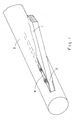
- an intersecting rigid assembly comprises a first constituent member 1 with a flat engagement portion 2, and a second constituent member 3 with a pair of brackets 4 and 5 enclosing between them a bracket base 6 and having upper edges 7 and 8, respectively.
- Fig. 1 shows only one single first constituent member 1 in association with the second constituent member 3. However, if desired, there may be several first constituent members 1 each forming an intersecting rigid assembly with the same second constituent member 3.
- Brackets 4 and 5 have pairs of registering holes 9 and 10 each with a slanting, inwardly convergent peripheral wall.
- a transversal bore 11 in the flat engagement portion 2 is aligned with holes 9 and 10 forming with them a tightening canal with bevels 12 and 13.
- the tightening device of the intersecting rigid assembly here shown comprises a first cylindrical member 15 with a frusto-conical head portion 16 having a central bore 17, and a second cylindrical member 18 having a frusto-conical head portion 19 and a screw-threaded axial bore 20.
- the device further comprises a tightening screw 21 fitting into the screw-threaded bore 20 and having a screw head 22 fitting into bore 17. As shown, bores 17 and 20 of, respectively, the first and second cylindrical members 15 and 18 are aligned.
- the first constituent member 1 is so positioned that its flat engagement portion 2 is received between brackets 4 and 5 of the second constituent member 3 with each transversal bore 11 of the flat engagement portion 2 being in rough alignment with a pair of registering holes 9 and 10 of brackets 4 and 5 of the second engagement member 3.
- the central axes of holes 9 and 10 on the one hand and of the transversal bore 11 on the other hand are at first out of register, as shown in Fig. 2, which is due to the fact that bracket holes 9 and 10 are larger than the head portions 16 and 19 of the cylindrical members and also due to the divergent end portions of bore 11.
- the intersecting rigid assembly according to the invention may comprise one or more tightening devices engaging a corresponding number of tightening canals.
Landscapes
- Engineering & Computer Science (AREA)
- General Engineering & Computer Science (AREA)
- Mechanical Engineering (AREA)
- Clamps And Clips (AREA)
- Connection Of Plates (AREA)
Applications Claiming Priority (2)
| Application Number | Priority Date | Filing Date | Title |
|---|---|---|---|
| IL10628693A IL106286A (en) | 1993-07-07 | 1993-07-07 | Surface connector |
| IL10628693 | 1993-07-07 |
Publications (2)
| Publication Number | Publication Date |
|---|---|
| EP0633403A1 true EP0633403A1 (de) | 1995-01-11 |
| EP0633403B1 EP0633403B1 (de) | 1996-07-31 |
Family
ID=11065029
Family Applications (1)
| Application Number | Title | Priority Date | Filing Date |
|---|---|---|---|
| EP94401415A Expired - Lifetime EP0633403B1 (de) | 1993-07-07 | 1994-06-23 | Oberflächenverbinder |
Country Status (6)
| Country | Link |
|---|---|
| US (1) | US5609434A (de) |
| EP (1) | EP0633403B1 (de) |
| CA (1) | CA2127505A1 (de) |
| DE (1) | DE69400349T2 (de) |
| IL (1) | IL106286A (de) |
| ZA (1) | ZA944560B (de) |
Families Citing this family (22)
| Publication number | Priority date | Publication date | Assignee | Title |
|---|---|---|---|---|
| US6010274A (en) * | 1997-06-03 | 2000-01-04 | Chrysler Corporation | Method and apparatus for attaching a stud to a member |
| US7375277B1 (en) * | 2000-06-26 | 2008-05-20 | Fatigue Technology, Inc. | Double flanged bushings and installation methods |
| US7448652B2 (en) * | 2003-07-31 | 2008-11-11 | Fatigue Technology Inc. | Tubular metal fitting expandable in a wall opening and method of installation |
| US20070110541A1 (en) * | 2005-10-28 | 2007-05-17 | Fatigue Technology, Inc. | Radially displaceable bushing for retaining a member relative to a structural workpiece |
| US7509829B2 (en) | 2005-12-28 | 2009-03-31 | Fatigue Technology, Inc. | Mandrel assembly and method of using the same |
| WO2007082077A1 (en) * | 2006-01-11 | 2007-07-19 | Fatigue Technology, Inc. | Bushing kits, bearings, and methods of installation |
| US7874059B2 (en) * | 2006-01-12 | 2011-01-25 | Siemens Energy, Inc. | Attachment for ceramic matrix composite component |
| ATE536957T1 (de) * | 2006-04-27 | 2011-12-15 | Fatigue Technology Inc | Ausrichtungsvorrichtung und anwendungsverfahren |
| EP2021635A2 (de) * | 2006-04-27 | 2009-02-11 | Fatigue Technology, Inc. | Wellenentlastende geometrische merkmale von radial in werkstücke expandierbaren strukturelementen |
| US7958766B2 (en) * | 2006-06-29 | 2011-06-14 | Fatigue Technology, Inc. | Self-aligning tools and a mandrel with retention sleeve |
| KR101468399B1 (ko) | 2006-08-28 | 2014-12-03 | 퍼티구 테크놀로지 인코포레이티드 | 설치/처리 시스템 및 이를 사용하는 방법 |
| EP2210001B1 (de) | 2007-10-16 | 2017-08-02 | Fatigue Technology, Inc. | Dehnbare befestigungsvorrichtungsanordnung mit deformiertem bund |
| US8777537B2 (en) * | 2007-12-26 | 2014-07-15 | Rolls-Royce North American Technologies, Inc. | Fastener with shear bushing |
| EP2259884B1 (de) * | 2008-03-07 | 2018-11-28 | Fatigue Technology, Inc. | Dehnbares element mit welleninhibitor und anwendungsverfahren dafür |
| WO2010009442A2 (en) | 2008-07-18 | 2010-01-21 | Fatigue Technology, Inc. | Nut plate assembly and methods of using the same |
| EP2417369B1 (de) | 2009-04-10 | 2014-04-02 | Fatigue Technology, Inc. | Verbinderanordnung für eine aufweitbare hülse und ein befestiger mit einem ziehdorn |
| US8647035B2 (en) * | 2009-12-16 | 2014-02-11 | Fatigue Technology, Inc. | Modular nut plate assemblies and methods of using the same |
| WO2012167136A2 (en) | 2011-06-03 | 2012-12-06 | Fatigue Technology, Inc. | Expandable crack inhibitors and methods of using the same |
| WO2012174215A2 (en) | 2011-06-15 | 2012-12-20 | Fatigue Technology, Inc | Modular nut plates with closed nut assemblies |
| EP2809482B1 (de) | 2012-01-30 | 2018-11-07 | Fatigue Technology, Inc. | Verarbeitungssystem und betriebsverfahren dafür |
| US8757665B2 (en) * | 2012-05-18 | 2014-06-24 | SkiBling, Inc. | Interchangeable two-piece insert for snow ski or snowboard |
| CN104470797B (zh) | 2012-07-30 | 2017-05-10 | 凯斯纽荷兰(中国)管理有限公司 | 用于履带式作业车辆的底架及其制造方法 |
Citations (3)
| Publication number | Priority date | Publication date | Assignee | Title |
|---|---|---|---|---|
| US2700172A (en) * | 1952-01-28 | 1955-01-25 | Frederick W Rohe | Sectional grommet for reinforcing openings in panels and sheets |
| FR2621362A1 (fr) * | 1987-10-02 | 1989-04-07 | Nuovo Pignone Spa | Boulon demontable pour assembler de facon tournante l'un a l'autre deux elements mecaniques de petites dimensions axiales, particulierement pour des systemes de leviers de machines textiles |
| US5004361A (en) * | 1989-09-07 | 1991-04-02 | Westinghouse Electric Corp. | Fastener for use at cryogenic temperatures, and tool therefor |
Family Cites Families (11)
| Publication number | Priority date | Publication date | Assignee | Title |
|---|---|---|---|---|
| US1150114A (en) * | 1914-02-24 | 1915-08-17 | Saul Ph Simon | Locking-screw. |
| US1339357A (en) * | 1919-01-27 | 1920-05-04 | Alois F Kopriva | Ax |
| US2516537A (en) * | 1946-09-20 | 1950-07-25 | Wetzel | Wheel bearing |
| DE820277C (de) * | 1949-03-30 | 1951-11-08 | Christian Gross | Stielbefestigung fuer Beile |
| US2549086A (en) * | 1949-10-19 | 1951-04-17 | Allis Chalmers Mfg Co | Means of fastening crank to reel tooth bar tube |
| US2957196A (en) * | 1958-11-25 | 1960-10-25 | Shur Lok Corp | Bolt and stud spacer for lightweight sandwich panels |
| US3258283A (en) * | 1963-10-07 | 1966-06-28 | Robbins & Assoc James S | Drilling shaft coupling having pin securing means |
| US3771410A (en) * | 1972-05-01 | 1973-11-13 | Vsi Corp | Fastener |
| US3851982A (en) * | 1972-08-10 | 1974-12-03 | Caterpillar Tractor Co | Shock cushioning mounting means for vehicle attachments |
| US5205667A (en) * | 1991-10-07 | 1993-04-27 | Montgomery Industries International Inc. | Pivot pin for shredder |
| US5452529A (en) * | 1993-08-25 | 1995-09-26 | Harnischfeger Corporation | Retaining device |
-
1993
- 1993-07-07 IL IL10628693A patent/IL106286A/en not_active IP Right Cessation
-
1994
- 1994-06-23 DE DE69400349T patent/DE69400349T2/de not_active Expired - Fee Related
- 1994-06-23 EP EP94401415A patent/EP0633403B1/de not_active Expired - Lifetime
- 1994-06-24 ZA ZA944560A patent/ZA944560B/xx unknown
- 1994-07-06 CA CA002127505A patent/CA2127505A1/en not_active Abandoned
-
1996
- 1996-06-28 US US08/672,241 patent/US5609434A/en not_active Expired - Fee Related
Patent Citations (3)
| Publication number | Priority date | Publication date | Assignee | Title |
|---|---|---|---|---|
| US2700172A (en) * | 1952-01-28 | 1955-01-25 | Frederick W Rohe | Sectional grommet for reinforcing openings in panels and sheets |
| FR2621362A1 (fr) * | 1987-10-02 | 1989-04-07 | Nuovo Pignone Spa | Boulon demontable pour assembler de facon tournante l'un a l'autre deux elements mecaniques de petites dimensions axiales, particulierement pour des systemes de leviers de machines textiles |
| US5004361A (en) * | 1989-09-07 | 1991-04-02 | Westinghouse Electric Corp. | Fastener for use at cryogenic temperatures, and tool therefor |
Also Published As
| Publication number | Publication date |
|---|---|
| EP0633403B1 (de) | 1996-07-31 |
| DE69400349D1 (de) | 1996-09-05 |
| CA2127505A1 (en) | 1995-01-08 |
| IL106286A (en) | 1996-05-14 |
| DE69400349T2 (de) | 1997-01-02 |
| US5609434A (en) | 1997-03-11 |
| ZA944560B (en) | 1995-02-20 |
Similar Documents
| Publication | Publication Date | Title |
|---|---|---|
| EP0633403A1 (de) | Oberflächenverbinder | |
| EP2016649B1 (de) | Steckverbindung | |
| US4140365A (en) | Fiber optic cable connector housing | |
| EP0475415B1 (de) | Mehrpoliger elektrischer Verbinder | |
| US4749251A (en) | Connector locking system | |
| JPH0359651B2 (de) | ||
| US5527190A (en) | Jack plug | |
| DE69423381T2 (de) | Anschlussdosen-Montagesatz für Datenübertragung | |
| DE2317040B2 (de) | Steckklemme zum Verbinden starrer elektrischer Leiter | |
| KR860006848A (ko) | 인쇄회로판 접속장치 | |
| EP1172673A2 (de) | Ausrichtungssystem für faseroptische Stecker | |
| US4090772A (en) | Low insertion force electrical connector | |
| US4693542A (en) | Electrical screw connection | |
| US4557653A (en) | Captive panel screw | |
| US4181391A (en) | Polarized electrical connector | |
| US5383796A (en) | Electrical connector with improved strain relief means | |
| US4565464A (en) | Clamping joint | |
| GB2083159A (en) | Panel connector | |
| GB2262396A (en) | Connector for elongate objects | |
| US4724616A (en) | Panel punch | |
| US6047464A (en) | Removal tool | |
| GB2300239A (en) | Connector assembly for furniture members | |
| GB2119051A (en) | Furniture fitting | |
| GB2264925A (en) | Device for storing cables | |
| US5199906A (en) | Electrical connector |
Legal Events
| Date | Code | Title | Description |
|---|---|---|---|
| PUAI | Public reference made under article 153(3) epc to a published international application that has entered the european phase |
Free format text: ORIGINAL CODE: 0009012 |
|
| AK | Designated contracting states |
Kind code of ref document: A1 Designated state(s): DE FR GB |
|
| 17P | Request for examination filed |
Effective date: 19950323 |
|
| 17Q | First examination report despatched |
Effective date: 19951004 |
|
| GRAH | Despatch of communication of intention to grant a patent |
Free format text: ORIGINAL CODE: EPIDOS IGRA |
|
| GRAH | Despatch of communication of intention to grant a patent |
Free format text: ORIGINAL CODE: EPIDOS IGRA |
|
| GRAA | (expected) grant |
Free format text: ORIGINAL CODE: 0009210 |
|
| AK | Designated contracting states |
Kind code of ref document: B1 Designated state(s): DE FR GB |
|
| REF | Corresponds to: |
Ref document number: 69400349 Country of ref document: DE Date of ref document: 19960905 |
|
| ET | Fr: translation filed | ||
| PLBE | No opposition filed within time limit |
Free format text: ORIGINAL CODE: 0009261 |
|
| STAA | Information on the status of an ep patent application or granted ep patent |
Free format text: STATUS: NO OPPOSITION FILED WITHIN TIME LIMIT |
|
| 26N | No opposition filed | ||
| PG25 | Lapsed in a contracting state [announced via postgrant information from national office to epo] |
Ref country code: FR Free format text: LAPSE BECAUSE OF NON-PAYMENT OF DUE FEES Effective date: 19980227 |
|
| PG25 | Lapsed in a contracting state [announced via postgrant information from national office to epo] |
Ref country code: DE Free format text: LAPSE BECAUSE OF NON-PAYMENT OF DUE FEES Effective date: 19980303 |
|
| REG | Reference to a national code |
Ref country code: FR Ref legal event code: ST |
|
| REG | Reference to a national code |
Ref country code: FR Ref legal event code: ST |
|
| PG25 | Lapsed in a contracting state [announced via postgrant information from national office to epo] |
Ref country code: GB Free format text: LAPSE BECAUSE OF NON-PAYMENT OF DUE FEES Effective date: 19980623 |
|
| GBPC | Gb: european patent ceased through non-payment of renewal fee |
Effective date: 19980623 |