EP0633460A2 - Dispositif de surveillance prolongée pour réservoirs à double paroi, en particulier des fonds à double paroi - Google Patents
Dispositif de surveillance prolongée pour réservoirs à double paroi, en particulier des fonds à double paroi Download PDFInfo
- Publication number
- EP0633460A2 EP0633460A2 EP94107776A EP94107776A EP0633460A2 EP 0633460 A2 EP0633460 A2 EP 0633460A2 EP 94107776 A EP94107776 A EP 94107776A EP 94107776 A EP94107776 A EP 94107776A EP 0633460 A2 EP0633460 A2 EP 0633460A2
- Authority
- EP
- European Patent Office
- Prior art keywords
- sensor cable
- intermediate layer
- double
- walled
- floor
- Prior art date
- Legal status (The legal status is an assumption and is not a legal conclusion. Google has not performed a legal analysis and makes no representation as to the accuracy of the status listed.)
- Granted
Links
Images


Classifications
-
- G—PHYSICS
- G01—MEASURING; TESTING
- G01M—TESTING STATIC OR DYNAMIC BALANCE OF MACHINES OR STRUCTURES; TESTING OF STRUCTURES OR APPARATUS, NOT OTHERWISE PROVIDED FOR
- G01M3/00—Investigating fluid-tightness of structures
- G01M3/02—Investigating fluid-tightness of structures by using fluid or vacuum
- G01M3/04—Investigating fluid-tightness of structures by using fluid or vacuum by detecting the presence of fluid at the leakage point
- G01M3/16—Investigating fluid-tightness of structures by using fluid or vacuum by detecting the presence of fluid at the leakage point using electric detection means
- G01M3/165—Investigating fluid-tightness of structures by using fluid or vacuum by detecting the presence of fluid at the leakage point using electric detection means by means of cables or similar elongated devices, e.g. tapes
-
- G—PHYSICS
- G01—MEASURING; TESTING
- G01M—TESTING STATIC OR DYNAMIC BALANCE OF MACHINES OR STRUCTURES; TESTING OF STRUCTURES OR APPARATUS, NOT OTHERWISE PROVIDED FOR
- G01M3/00—Investigating fluid-tightness of structures
- G01M3/02—Investigating fluid-tightness of structures by using fluid or vacuum
- G01M3/04—Investigating fluid-tightness of structures by using fluid or vacuum by detecting the presence of fluid at the leakage point
- G01M3/042—Investigating fluid-tightness of structures by using fluid or vacuum by detecting the presence of fluid at the leakage point by using materials which expand, contract, disintegrate, or decompose in contact with a fluid
- G01M3/045—Investigating fluid-tightness of structures by using fluid or vacuum by detecting the presence of fluid at the leakage point by using materials which expand, contract, disintegrate, or decompose in contact with a fluid with electrical detection means
-
- G—PHYSICS
- G01—MEASURING; TESTING
- G01M—TESTING STATIC OR DYNAMIC BALANCE OF MACHINES OR STRUCTURES; TESTING OF STRUCTURES OR APPARATUS, NOT OTHERWISE PROVIDED FOR
- G01M3/00—Investigating fluid-tightness of structures
- G01M3/02—Investigating fluid-tightness of structures by using fluid or vacuum
- G01M3/04—Investigating fluid-tightness of structures by using fluid or vacuum by detecting the presence of fluid at the leakage point
- G01M3/16—Investigating fluid-tightness of structures by using fluid or vacuum by detecting the presence of fluid at the leakage point using electric detection means
- G01M3/18—Investigating fluid-tightness of structures by using fluid or vacuum by detecting the presence of fluid at the leakage point using electric detection means for pipes, cables or tubes; for pipe joints or seals; for valves; for welds; for containers, e.g. radiators
- G01M3/186—Investigating fluid-tightness of structures by using fluid or vacuum by detecting the presence of fluid at the leakage point using electric detection means for pipes, cables or tubes; for pipe joints or seals; for valves; for welds; for containers, e.g. radiators for containers, e.g. radiators
Definitions
- the invention relates to a device for long-term leak monitoring on double-walled vascular systems, in particular on double-walled tank bottoms, according to the preamble of patent claim 1.
- flat-bottom tanks for example, are provided with a raised floor, so that in the event of signs of corrosion or the occurrence of a leak in the intermediate floor, the outer, second floor guarantees safety against the escape of environmentally hazardous substances in the tank.
- the space between the two floors i. H. the intermediate floor and the outer floor of the flat-bottom tank are constantly monitored in order to be able to determine whether the intermediate floor has a leak, in order to empty the tank after such a leak has been found and to be able to repair the leaky or damaged intermediate floor.
- vacuum monitoring systems For this purpose, a defined vacuum is applied to the space between the two floors, a pressure monitoring device being used to determine whether the vacuum changes due to a leak. A separate vacuum monitoring system is required for each tank, which increases the costs for such a system.
- a further disadvantage of the vacuum leak monitoring device is that it cannot be determined whether a determined pressure loss is due to leaks in system flange connections, leaks in the outer floor or leaks in the intermediate floor. If in doubt, the tank must be emptied with considerable effort in order to check where the cause of the leak found is.
- the object of the invention is therefore to create a device for long-term leak monitoring on double-walled vessel systems, in particular double-walled tank bottoms, which allows a large number of double-walled tank bottoms to be monitored cyclically or simultaneously with regard to the occurrence of leaks with little effort, whether a leak has occurred in the outer floor or in the intermediate floor, and the device should be able to estimate the size of the leak and the location where the leak occurred.
- the basic idea of the invention is, on the inside of the outer bottom, for. B. a double-walled tank bottom to form a monitoring room, which receives a sensor cable, which is able to determine incoming liquids by locally changing the dielectric constant of the sensor cable.
- the sensor cable is subjected to high-frequency energy according to the pulse-echo method, the reflected measurement data being compared with a previously recorded, stored normal image in a downstream evaluation device.
- leakage development or spread can be observed become. At the same time, several leaks can be determined at different locations.
- the device according to the invention is designed such that an intermediate layer is formed on the outer bottom, which on the one hand receives the sensor cable and on the other hand enables the intermediate floor to be supported.
- the intermediate layer must on the one hand absorb the mechanical loads when the tank is full and safely derive the corresponding forces and on the other hand the penetration and spreading of a medium in the tank, e.g. B. little hinder a liquid in the interstitial space.
- the device according to the invention can be retrofitted in a simple manner, in which the monitoring room is retrofitted into an existing tank with the aid of an additional floor, as a result of which it is possible to react to changed legal provisions, for example the Water Resources Act, with little effort. In particular, it is then possible to store water-polluting liquids in such a way that contamination or an adverse change in the waters can be avoided.
- the cylindrical flat-bottom tank on which the exemplary embodiment is based has a side wall 1 with a lower or outer bottom 2.
- An intermediate layer 3 is applied to the outer bottom 2 and consists, for example, of isosceles angle steel.
- the two legs 4 of the angle steel intermediate layer 3 are connected to the outer bottom 2 by tack welding.
- an angle steel intermediate layer 3 also profiles with a different cross-sectional area, for. B. square profile can be used. It is also possible to place a network of solid metal profiles on the inside of the outer floor 2, the distance between the outer floor 2 and the intermediate floor or inner bottom 5 is adjustable. In the lattice or mesh structure of the full profile, meandering notches are then made, for example, which serve to receive the sensor cable 6. In order to ensure an unhindered spreading of liquid on the outer floor 2, it is necessary that the full metal profile of the lattice or mesh structure has a surface that is profiled, for example, as is customary with structural steel.
- the aforementioned sensor cable 6 is laid in a predetermined manner inside the angle steel intermediate layer 3. This ensures that damage to the sensor cable 6 is excluded when the intermediate or inner base 5 is placed or welded. At the same time, during the later operation of the monitoring device, the defined position of the sensor cable 6 enables the location at which the leak occurred to be clearly determined.
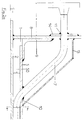
- FIG. 2a shows the representation of the wall connection by means of a connecting pipe 7.
- the wall connection is designed such that the double-walled structure or the monitoring space 50 formed by the outer floor 2 and the inner floor 5 remains unaffected.
- the connecting tube 7 has a flange 8 on the outside. The connecting tube 7 with the flange 8 can be used for the pressure test of the monitoring space 50.
- the sensor cable 6 is fed in and out through the interior of the connecting tube 7.
- the connecting tube 7 itself is bent to form a step, the passage of the connecting tube 7 through the side wall 8 above a circumferential angle 9 for fastening the inner bottom 5.
- the circumferential angle 9 also serves to compensate for tolerances T when welding the inner base 5.
- the stepped connecting tube 7 is in the monitoring space 50, d. H. the space between outer floor 2 and inner floor 5 is inserted and welded tight.
- the connecting pipe 7 is butt welded against a selected intermediate layer 3, in the example shown the isosceles angle steel. This ensures that the sensor cable 6 is guided protected up to the intermediate layer 3.
- a cover plate 13 is provided in the interior of the tank above the connecting pipe 7.
- An outer cover or reinforcing plate 14 is provided in the passage area 11.
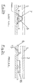
- the outer bottom 2 of the cylindrical flat-bottom tank is essentially flat, the tank bottom being inclined by a defined angle.
- the intermediate layers 3 are provided with cutouts 15, 16 according to FIG. 2c.
- the recess 15 has a semicircular shape or the recess 16 is essentially rectangular.
- the cutouts 15, 16 can either be made before the intermediate layer 3 is fastened to the outer bottom 2 by welding, or a predetermined area can be separated from the intermediate layer 3 after welding using a suitable tool.
- the size of the recesses 15, 16 are chosen so that the mechanical strength of the intermediate layers 3 essentially is retained and the flow of liquid penetrating is only slightly hindered.
- the outer bottom 2 of the tank can also have beads or can be designed as a round bottom.
- the intermediate layer 3 it is expedient to design the intermediate layer 3 in such a way that a rapid spreading of penetrating liquid is hindered. This makes it easier to determine the original location of the penetration of the liquid.
- the sensor cable 6 used has a preferably coaxial structure, the dielectric, which is arranged between the inner and outer conductor of the coaxial sensor cable 6, having the property of changing its dielectric constant ⁇ upon contact with liquids.
- the sensor cable 6 is designed so that even non-conductive liquids can be detected without problems. Due to the pulse reflection technology used, several leaks can be detected, located and analyzed on a single sensor cable 6. Before the actual monitoring begins, an echo image of the sensor cable 6 is recorded in the normal state using an electronic device. The reflection of the impulses A memory is stored on the sensor cable as a so-called normal image. Soiling of the cables or building moisture in the monitoring room can also be measured. In this way the triggering of a false alarm can be avoided. In the monitoring state, the current pulse-echo images are then compared with the normal image or with several normal images stored in a reference list.
- a possible leakage then moistens the sensor cable 6 at certain points, as a result of which the respective echo image changes and an alarm is triggered.
- the echo image obtained in the event of an alarm is then stored again and compared with further echo images arriving at a later point in time, so that the propagation or the propagation speed of the liquid which has entered through the leak can be calculated.
- the sensor cable used is capable of detecting both aqueous liquids and hydrocarbons.
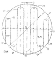
- FIGS. 3 and 4 are intended to explain, for example, the laying of the sensor cable 6 on the inner surface of the outer bottom 2 largely within the intermediate layers 3.
- a first sensor cable 61 runs essentially equally spaced from the side wall 1 in a semicircular shape between the sensor cable input 17 and the sensor cable output 18. With respect to an axis of symmetry 19, the mirror image runs to the first Sensor cable 61, a second sensor cable 62 equally spaced from the opposite part of the side wall 1.
- a third sensor cable 63 is guided over a predetermined distance S parallel to the axis of symmetry 19 in such a way that a semicircular course is formed which is concentric with the center M of the outer bottom and is on the opposite side again in a predetermined, parallel to the symmetry axis Section S merges.
- the location of the arrangement of a fourth sensor cable 64 is obtained by mirroring the third sensor cable 63 on the axis of symmetry 19.
- the two semicircles of the third and fourth sensor cables 63, 64, which form a full circle by mirroring on the axis of symmetry 19, are designed such that the full circle diameter corresponds essentially to 0.5 times the diameter of the tank.
- a meandering manner shows two meanders, mirrored on an axis of symmetry 20, of a first sensor cable 610 and a second sensor cable 620.
- the respective sensor cable inputs and outputs 18 are located on a single side of the side wall 1.
- 4 to provide a connecting meander 24 in the interior of the tank, so that the sensor cable exits 18 can be dispensed with.
- the intermediate layers 3 are designed according to FIG. 4 so that they are fastened to the inside of the outer bottom 2 essentially perpendicular to the gradient direction G. This makes it easier to determine the rate of propagation of liquid possibly penetrating into the monitoring space 50.
- the sensor cable 6 is expediently arranged within the intermediate layers 3 in such a way that good contact is made with the inside of the outer base 2. This ensures that certain amounts of penetrating liquid flow under the sensor cable 6. However, since the dielectric of the sensor cable 6 has pronounced capillary properties, less contact with the inside of the outer base 2 is generally also harmless for effective monitoring of the monitoring space 50.
- the arcuate meandering sections 21 are not covered by the intermediate layer 3 or the isosceles angle steel and can expediently have deflection rollers 23, which are optionally rotatably attached to the inside of the outer bottom 2. The guide rollers 23 make it easier, if repairs are required, to thread or thread the sensor cable 6 into the monitoring space.
- the sensor cable 6 can cover the inside of the outer bottom 2 in a spiral. This is particularly advantageous if the outer floor 2 is provided with a slope toward the center M, i. H. the center point M lies at the lowest point.
- the tank diameter was 15 m and the distance between the meandering sensor cables was 1.5 m on average.
- Light heating oil was poured into the monitoring space 50 through a 1.8 mm bore at a point furthest away from the sensor cable 6 and above the slope G. After an average of 5 to 6 minutes. the first leak monitoring alarm was given, and the location of the liquid's impact on the sensor cable 6 could be determined exactly. Because of the known gradient, the bottom segment which has the leak can then be easily identified. Another alarm was then triggered after a short time because the flowing medium is the next down-slope sensor cable section had achieved. The flow rate and the size of the leak could already be determined from these two measurements.
- the sensor cable 6 was then brought into contact with water at a location far from the first leak.
- the electronic evaluation system coupled to the device for long-term leak monitoring then triggered a third alarm, it being recognizable that the medium which triggered the third alarm was a different substance, namely water.
- the device according to the invention it is thus possible to replace the previously known vacuum leak monitoring devices and to achieve a qualitative leap in monitoring since not only the fact of the presence of a leak, but also the location and the medium flowing through the leak can be recognized.
- Existing tank systems in particular standing flat-bottom tanks, can be retrofitted in a simple manner with the device according to the invention, and the water law type approvals can thus be met.
- the dielectric of which can be changed by the influence of liquids, tanks with any inside diameter can be monitored with little effort. Since it is possible to provide a multiplex or a series-connected operation of several monitoring devices, the costs for the electronic generation of the pulse signal used or the evaluation of the pulse echo are minimized.
- the features of the device according to the invention ensure that, on the one hand, the stability of a subsequently installed double-wall system is provided, adequate protection and an exact position of the sensor cable and a defined influence on the liquid which spreads in the event of a leak is ensured.
Landscapes
- Physics & Mathematics (AREA)
- General Physics & Mathematics (AREA)
- Examining Or Testing Airtightness (AREA)
Applications Claiming Priority (2)
| Application Number | Priority Date | Filing Date | Title |
|---|---|---|---|
| DE4322859 | 1993-07-08 | ||
| DE4322859A DE4322859C2 (de) | 1993-07-08 | 1993-07-08 | Einrichtung zur Langzeit-Lecküberwachung an doppelwandigen Gefäßsystemen, insbesondere doppelwandigen Tankböden |
Publications (3)
| Publication Number | Publication Date |
|---|---|
| EP0633460A2 true EP0633460A2 (fr) | 1995-01-11 |
| EP0633460A3 EP0633460A3 (en) | 1995-01-18 |
| EP0633460B1 EP0633460B1 (fr) | 1998-04-22 |
Family
ID=6492322
Family Applications (1)
| Application Number | Title | Priority Date | Filing Date |
|---|---|---|---|
| EP94107776A Expired - Lifetime EP0633460B1 (fr) | 1993-07-08 | 1994-05-19 | Dispositif de surveillance prolongée pour réservoirs à double paroi, en particulier des fonds à double paroi |
Country Status (4)
| Country | Link |
|---|---|
| EP (1) | EP0633460B1 (fr) |
| AT (1) | ATE165445T1 (fr) |
| DE (2) | DE4322859C2 (fr) |
| ES (1) | ES2115098T3 (fr) |
Cited By (5)
| Publication number | Priority date | Publication date | Assignee | Title |
|---|---|---|---|---|
| EP1047082A1 (fr) * | 1999-04-24 | 2000-10-25 | GNS GESELLSCHAFT FÜR NUKLEAR-SERVICE mbH | Conteneur de stockage pour matières radioactives |
| DE10256913B3 (de) * | 2002-11-28 | 2004-04-08 | Cta Industriemontage Gmbh | Vorrichtung zur Leckageüberwachung an senkrechten Gefäßwänden |
| DE102004002217A1 (de) * | 2004-01-15 | 2005-08-11 | S. Müller Patent Entwicklungs und Verpachtungs GmbH & Co. KG | Einrichtung zur Langzeit-Lecküberwachung von doppelwandigen Gefäßsystemen, insbesondere Flachtankbauwerken mit doppeltem Tankboden |
| EP1597554B1 (fr) * | 2003-02-07 | 2008-01-30 | Universität Leipzig | Procede pour determiner au moins un parametre d'etat d'un systeme d'etancheite et systeme d'etancheite |
| US9739546B2 (en) | 2010-10-22 | 2017-08-22 | Alfa Laval Corporate Ab | Heat exchanger plate and a plate heat exchanger with insulated sensor internal to heat exchange area |
Families Citing this family (9)
| Publication number | Priority date | Publication date | Assignee | Title |
|---|---|---|---|---|
| DK0783100T3 (da) | 1995-12-19 | 2002-06-17 | Sepp Mueller | Indretning til langtids-lækageovervågning af en tanks kappe |
| DE19600970C1 (de) * | 1995-12-19 | 1996-11-28 | Sepp Mueller | Einrichtung zur Langzeit-Tankmantel-Lecküberwachung |
| DE19753570A1 (de) * | 1997-12-03 | 1999-06-17 | Krueger & Schuette Kerapid | Vorrichtung zur Dichtigkeitsprüfung |
| WO1999050635A1 (fr) | 1998-03-31 | 1999-10-07 | Mueller Sepp | Dispositif pour surveiller des fuites de façon prolongee, destine notamment a des reservoirs plats |
| DE10256915B4 (de) * | 2002-11-28 | 2006-10-26 | Cta Tank- Und Anlagenbau Gmbh | Vorrichtung zur Leckageüberwachung von Tankböden und Eckanschlüssen von Tankböden und Tankmantel |
| DE102005008308B4 (de) * | 2005-02-17 | 2007-04-05 | Cta Tank- Und Anlagenbau Gmbh | Verfahren zur Lecksuche an Leckschutzauskleidungen von Tanks und Behältern o. dgl. |
| AT501866B1 (de) * | 2005-05-23 | 2007-07-15 | Federspiel Per G Mag Dr | Flachboden-tankanlage für die lagerung von brennbaren und/oder umweltschädigenden flüssigkeiten |
| DE102007022039B4 (de) * | 2007-05-08 | 2009-07-09 | Hochschule Mannheim | Sensoranordnung |
| DE102008047257A1 (de) * | 2008-09-14 | 2010-04-08 | Sicherungsgerätebau GmbH | Sensoreinheit zur Kontrolle von Überwachungsräumen von doppelwandigen Behältern oder doppelwandigen Rohren oder doppelwandigen Behältnissen |
Family Cites Families (8)
| Publication number | Priority date | Publication date | Assignee | Title |
|---|---|---|---|---|
| DE2450559A1 (de) * | 1971-10-27 | 1976-04-29 | Erich Barth | Behaelterboden fuer innenbehaelter von doppelwandigen stehenden lagerbehaeltern |
| US4538141A (en) * | 1982-10-04 | 1985-08-27 | Chevron Research Company | Water detection subassembly and method of forming same, for computer processing centers |
| DE3336335C2 (de) * | 1983-10-06 | 1987-01-08 | Barlian, Reinhold, Dipl.-Ing.(FH), 6990 Bad Mergentheim | Einrichtung zur Überwachung eines Behälters |
| DE3426833A1 (de) * | 1984-07-20 | 1986-01-23 | W.L. Gore & Co GmbH, 8011 Putzbrunn | Lecksuchvorrichtung fuer saure und basische medien |
| DE3620976C2 (de) * | 1986-06-23 | 1996-07-04 | Gewerk Keramchemie | Chemisch beständiger, flüssigkeitsdichter Belag für Auffangräume, Behälter oder dergleichen aus Beton |
| DE3937638A1 (de) * | 1989-11-11 | 1991-05-23 | Becker Annette | Auffangwanne fuer umweltgefaehrdende chemikalien mit einer abdichtungsschicht aus bodenplatten aus metall |
| DE4015190A1 (de) * | 1990-05-11 | 1991-11-21 | Gore W L & Ass Gmbh | Flachbodentank und verfahren zur leckueberwachung von flachbodentanks |
| DE4021664A1 (de) * | 1990-07-07 | 1992-01-16 | Wrede & Niedecken Verwaltung | Vorrichtung und verfahren zur ermittlung von leckagen an isolierten, ein stroemungsmedium beinhaltenden beziehungsweise fuehrenden bauteilen |
-
1993
- 1993-07-08 DE DE4322859A patent/DE4322859C2/de not_active Expired - Fee Related
-
1994
- 1994-05-19 ES ES94107776T patent/ES2115098T3/es not_active Expired - Lifetime
- 1994-05-19 DE DE59405757T patent/DE59405757D1/de not_active Expired - Fee Related
- 1994-05-19 EP EP94107776A patent/EP0633460B1/fr not_active Expired - Lifetime
- 1994-05-19 AT AT94107776T patent/ATE165445T1/de not_active IP Right Cessation
Cited By (6)
| Publication number | Priority date | Publication date | Assignee | Title |
|---|---|---|---|---|
| EP1047082A1 (fr) * | 1999-04-24 | 2000-10-25 | GNS GESELLSCHAFT FÜR NUKLEAR-SERVICE mbH | Conteneur de stockage pour matières radioactives |
| DE10256913B3 (de) * | 2002-11-28 | 2004-04-08 | Cta Industriemontage Gmbh | Vorrichtung zur Leckageüberwachung an senkrechten Gefäßwänden |
| EP1597554B1 (fr) * | 2003-02-07 | 2008-01-30 | Universität Leipzig | Procede pour determiner au moins un parametre d'etat d'un systeme d'etancheite et systeme d'etancheite |
| DE102004002217A1 (de) * | 2004-01-15 | 2005-08-11 | S. Müller Patent Entwicklungs und Verpachtungs GmbH & Co. KG | Einrichtung zur Langzeit-Lecküberwachung von doppelwandigen Gefäßsystemen, insbesondere Flachtankbauwerken mit doppeltem Tankboden |
| DE102004002217B4 (de) * | 2004-01-15 | 2006-02-09 | S. Müller Patent Entwicklungs und Verpachtungs GmbH & Co. KG | Einrichtung zur Langzeit-Lecküberwachung von doppelwandigen Gefäßsystemen, insbesondere Flachtankbauwerken mit doppeltem Tankboden |
| US9739546B2 (en) | 2010-10-22 | 2017-08-22 | Alfa Laval Corporate Ab | Heat exchanger plate and a plate heat exchanger with insulated sensor internal to heat exchange area |
Also Published As
| Publication number | Publication date |
|---|---|
| EP0633460A3 (en) | 1995-01-18 |
| DE4322859A1 (de) | 1995-01-12 |
| DE4322859C2 (de) | 1996-01-11 |
| DE59405757D1 (de) | 1998-05-28 |
| ES2115098T3 (es) | 1998-06-16 |
| EP0633460B1 (fr) | 1998-04-22 |
| ATE165445T1 (de) | 1998-05-15 |
Similar Documents
| Publication | Publication Date | Title |
|---|---|---|
| DE4322859C2 (de) | Einrichtung zur Langzeit-Lecküberwachung an doppelwandigen Gefäßsystemen, insbesondere doppelwandigen Tankböden | |
| DE4405238C2 (de) | Anordnung zur Messung des Füllstands in einem Behälter | |
| DE69526213T2 (de) | Verfahren und vorrichtung zur inspektion eines rohres mit elektromagnetischer strahlung | |
| DE2431907C3 (de) | Verfahren und Vorrichtung zur Bestimmung von Konzentrationsprofilen flüssiger oder gasförmiger Stoffe längs einer Strecke | |
| DE3124875A1 (de) | "messsonde" | |
| DE3620976C2 (de) | Chemisch beständiger, flüssigkeitsdichter Belag für Auffangräume, Behälter oder dergleichen aus Beton | |
| EP0456094B1 (fr) | Réservoir à fond plat | |
| EP0525593B1 (fr) | Tuyau capteur pour le monitorage d'un milieu | |
| DE3531479A1 (de) | Messfuehler fuer korrosionspruefung | |
| DE10110540A1 (de) | Lagerbehälter für wassergefährdende Flüssigkeiten | |
| DE2917255A1 (de) | Rissanzeigeeinrichtung zur ueberwachung der isolierung von fluessiggastanks | |
| DE3330059A1 (de) | Fuellstandsmesser fuer fluessigkeitsbehaelter | |
| WO1997040355A1 (fr) | Procede et dispositif pour verifier la solidite de mats ancres verticalement | |
| DE4124640C2 (de) | Rohrleitungssystem | |
| DE102009031807A1 (de) | Montierungsvorrichtung für eine Füllstandmessvorrichtung | |
| DE19638734C2 (de) | Vorrichtung zur selektiven Detektion und zur Ortung von Leckageflüssigkeiten an Abdichtungssystemen | |
| DE19600970C1 (de) | Einrichtung zur Langzeit-Tankmantel-Lecküberwachung | |
| DE3686389T2 (de) | Vorrichtung zur leckaufnahme und leckueberwachung fuer unterirdische behaelter. | |
| EP0225895A1 (fr) | Dispositif recepteur d'integration pour rayonnement laser | |
| DE3336335C2 (de) | Einrichtung zur Überwachung eines Behälters | |
| WO1999050635A1 (fr) | Dispositif pour surveiller des fuites de façon prolongee, destine notamment a des reservoirs plats | |
| DE102004035757B3 (de) | Anordnung zur Bestimmung der Höhe eines Flüssigkeitsstandes | |
| EP3605029B1 (fr) | Procédé de détermination d'un état de commutation d'un capteur d'impédance et capteur d'impédance | |
| EP0783100B1 (fr) | Dispositif de surveillance à long terme de fuites des parois d'un récipient | |
| DE2553789A1 (de) | Verfahren und anordnung zum feststellen und lokalisieren von schadhaften stellen in einer isolierten leitung |
Legal Events
| Date | Code | Title | Description |
|---|---|---|---|
| PUAI | Public reference made under article 153(3) epc to a published international application that has entered the european phase |
Free format text: ORIGINAL CODE: 0009012 |
|
| PUAL | Search report despatched |
Free format text: ORIGINAL CODE: 0009013 |
|
| AK | Designated contracting states |
Kind code of ref document: A2 Designated state(s): AT BE CH DE ES FR GR IT LI LU NL PT SE |
|
| AK | Designated contracting states |
Kind code of ref document: A3 Designated state(s): AT BE CH DE ES FR GR IT LI LU NL PT SE |
|
| 17P | Request for examination filed |
Effective date: 19950208 |
|
| 17Q | First examination report despatched |
Effective date: 19960920 |
|
| GRAG | Despatch of communication of intention to grant |
Free format text: ORIGINAL CODE: EPIDOS AGRA |
|
| GRAG | Despatch of communication of intention to grant |
Free format text: ORIGINAL CODE: EPIDOS AGRA |
|
| GRAH | Despatch of communication of intention to grant a patent |
Free format text: ORIGINAL CODE: EPIDOS IGRA |
|
| GRAH | Despatch of communication of intention to grant a patent |
Free format text: ORIGINAL CODE: EPIDOS IGRA |
|
| GRAA | (expected) grant |
Free format text: ORIGINAL CODE: 0009210 |
|
| AK | Designated contracting states |
Kind code of ref document: B1 Designated state(s): AT BE CH DE ES FR GR IT LI LU NL PT SE |
|
| PG25 | Lapsed in a contracting state [announced via postgrant information from national office to epo] |
Ref country code: GR Free format text: LAPSE BECAUSE OF FAILURE TO SUBMIT A TRANSLATION OF THE DESCRIPTION OR TO PAY THE FEE WITHIN THE PRESCRIBED TIME-LIMIT Effective date: 19980422 |
|
| REF | Corresponds to: |
Ref document number: 165445 Country of ref document: AT Date of ref document: 19980515 Kind code of ref document: T |
|
| REG | Reference to a national code |
Ref country code: CH Ref legal event code: EP |
|
| ET | Fr: translation filed | ||
| ITF | It: translation for a ep patent filed | ||
| PG25 | Lapsed in a contracting state [announced via postgrant information from national office to epo] |
Ref country code: LU Free format text: LAPSE BECAUSE OF NON-PAYMENT OF DUE FEES Effective date: 19980519 |
|
| REF | Corresponds to: |
Ref document number: 59405757 Country of ref document: DE Date of ref document: 19980528 |
|
| PG25 | Lapsed in a contracting state [announced via postgrant information from national office to epo] |
Ref country code: LI Free format text: LAPSE BECAUSE OF NON-PAYMENT OF DUE FEES Effective date: 19980531 Ref country code: CH Free format text: LAPSE BECAUSE OF NON-PAYMENT OF DUE FEES Effective date: 19980531 |
|
| REG | Reference to a national code |
Ref country code: ES Ref legal event code: FG2A Ref document number: 2115098 Country of ref document: ES Kind code of ref document: T3 |
|
| PG25 | Lapsed in a contracting state [announced via postgrant information from national office to epo] |
Ref country code: PT Free format text: LAPSE BECAUSE OF FAILURE TO SUBMIT A TRANSLATION OF THE DESCRIPTION OR TO PAY THE FEE WITHIN THE PRESCRIBED TIME-LIMIT Effective date: 19980722 |
|
| REG | Reference to a national code |
Ref country code: CH Ref legal event code: PL |
|
| PLBE | No opposition filed within time limit |
Free format text: ORIGINAL CODE: 0009261 |
|
| STAA | Information on the status of an ep patent application or granted ep patent |
Free format text: STATUS: NO OPPOSITION FILED WITHIN TIME LIMIT |
|
| 26N | No opposition filed | ||
| PGFP | Annual fee paid to national office [announced via postgrant information from national office to epo] |
Ref country code: AT Payment date: 20020523 Year of fee payment: 9 |
|
| PGFP | Annual fee paid to national office [announced via postgrant information from national office to epo] |
Ref country code: SE Payment date: 20020524 Year of fee payment: 9 |
|
| PG25 | Lapsed in a contracting state [announced via postgrant information from national office to epo] |
Ref country code: AT Free format text: LAPSE BECAUSE OF NON-PAYMENT OF DUE FEES Effective date: 20030519 |
|
| PG25 | Lapsed in a contracting state [announced via postgrant information from national office to epo] |
Ref country code: SE Free format text: LAPSE BECAUSE OF NON-PAYMENT OF DUE FEES Effective date: 20030520 |
|
| EUG | Se: european patent has lapsed | ||
| PGFP | Annual fee paid to national office [announced via postgrant information from national office to epo] |
Ref country code: NL Payment date: 20050518 Year of fee payment: 12 |
|
| PGFP | Annual fee paid to national office [announced via postgrant information from national office to epo] |
Ref country code: FR Payment date: 20050519 Year of fee payment: 12 |
|
| PGFP | Annual fee paid to national office [announced via postgrant information from national office to epo] |
Ref country code: BE Payment date: 20050523 Year of fee payment: 12 |
|
| PGFP | Annual fee paid to national office [announced via postgrant information from national office to epo] |
Ref country code: ES Payment date: 20050531 Year of fee payment: 12 |
|
| PG25 | Lapsed in a contracting state [announced via postgrant information from national office to epo] |
Ref country code: ES Free format text: LAPSE BECAUSE OF NON-PAYMENT OF DUE FEES Effective date: 20060520 |
|
| PG25 | Lapsed in a contracting state [announced via postgrant information from national office to epo] |
Ref country code: BE Free format text: LAPSE BECAUSE OF NON-PAYMENT OF DUE FEES Effective date: 20060531 |
|
| PG25 | Lapsed in a contracting state [announced via postgrant information from national office to epo] |
Ref country code: NL Free format text: LAPSE BECAUSE OF NON-PAYMENT OF DUE FEES Effective date: 20061201 |
|
| NLV4 | Nl: lapsed or anulled due to non-payment of the annual fee |
Effective date: 20061201 |
|
| REG | Reference to a national code |
Ref country code: FR Ref legal event code: ST Effective date: 20070131 |
|
| PGFP | Annual fee paid to national office [announced via postgrant information from national office to epo] |
Ref country code: DE Payment date: 20070730 Year of fee payment: 14 |
|
| REG | Reference to a national code |
Ref country code: ES Ref legal event code: FD2A Effective date: 20060520 |
|
| BERE | Be: lapsed |
Owner name: *MULLER SEPP Effective date: 20060531 |
|
| PGFP | Annual fee paid to national office [announced via postgrant information from national office to epo] |
Ref country code: IT Payment date: 20070516 Year of fee payment: 14 |
|
| PG25 | Lapsed in a contracting state [announced via postgrant information from national office to epo] |
Ref country code: FR Free format text: LAPSE BECAUSE OF NON-PAYMENT OF DUE FEES Effective date: 20060531 |
|
| PG25 | Lapsed in a contracting state [announced via postgrant information from national office to epo] |
Ref country code: DE Free format text: LAPSE BECAUSE OF NON-PAYMENT OF DUE FEES Effective date: 20081202 |
|
| PG25 | Lapsed in a contracting state [announced via postgrant information from national office to epo] |
Ref country code: IT Free format text: LAPSE BECAUSE OF NON-PAYMENT OF DUE FEES Effective date: 20080519 |