EP0633475A2 - Adapteur pour appareils électriques - Google Patents
Adapteur pour appareils électriques Download PDFInfo
- Publication number
- EP0633475A2 EP0633475A2 EP94110467A EP94110467A EP0633475A2 EP 0633475 A2 EP0633475 A2 EP 0633475A2 EP 94110467 A EP94110467 A EP 94110467A EP 94110467 A EP94110467 A EP 94110467A EP 0633475 A2 EP0633475 A2 EP 0633475A2
- Authority
- EP
- European Patent Office
- Prior art keywords
- test
- base part
- adapter
- measuring head
- housing
- Prior art date
- Legal status (The legal status is an assumption and is not a legal conclusion. Google has not performed a legal analysis and makes no representation as to the accuracy of the status listed.)
- Granted
Links
Images



Classifications
-
- G—PHYSICS
- G01—MEASURING; TESTING
- G01R—MEASURING ELECTRIC VARIABLES; MEASURING MAGNETIC VARIABLES
- G01R1/00—Details of instruments or arrangements of the types included in groups G01R5/00 - G01R13/00 and G01R31/00
- G01R1/02—General constructional details
- G01R1/04—Housings; Supporting members; Arrangements of terminals
- G01R1/0408—Test fixtures or contact fields; Connectors or connecting adaptors; Test clips; Test sockets
- G01R1/0416—Connectors, terminals
-
- H—ELECTRICITY
- H01—ELECTRIC ELEMENTS
- H01R—ELECTRICALLY-CONDUCTIVE CONNECTIONS; STRUCTURAL ASSOCIATIONS OF A PLURALITY OF MUTUALLY-INSULATED ELECTRICAL CONNECTING ELEMENTS; COUPLING DEVICES; CURRENT COLLECTORS
- H01R27/00—Coupling parts adapted for co-operation with two or more dissimilar counterparts
-
- H—ELECTRICITY
- H01—ELECTRIC ELEMENTS
- H01R—ELECTRICALLY-CONDUCTIVE CONNECTIONS; STRUCTURAL ASSOCIATIONS OF A PLURALITY OF MUTUALLY-INSULATED ELECTRICAL CONNECTING ELEMENTS; COUPLING DEVICES; CURRENT COLLECTORS
- H01R31/00—Coupling parts supported only by co-operation with counterpart
- H01R31/06—Intermediate parts for linking two coupling parts, e.g. adapter
Definitions
- the present invention relates to a test or measuring head for electrical testing and / or measuring devices with the further features of the preamble of claim 1.
- a measuring adapter for measuring electrical quantities which has a housing in which different measuring sensors are arranged.
- the handles can be extended from the tip of the housing in the manner of a multicolor ballpoint pen and brought into the functional position.
- the invention has for its object to develop a test and measuring head for electrical testing or measuring devices with the features of claim 1 such that it leads to an improvement in the possible uses with relatively low manufacturing costs and in particular also enables multi-pole contact configurations.
- This object is achieved by the characterizing features of claim 1, expedient refinements result from the subclaims.
- the invention offers the possibility, using a standardized base part in conjunction with specially designed adapter parts, to make better use of production capacities, as a result of which the production costs of a generic connection can be considerably reduced. Furthermore, the user can easily and quickly convert the connection according to the requirements and is therefore no longer restricted to a specific type of connection.
- a quick connection between the base part and adapter part is provided, for example in the form of a screw or bayonet connection or a combination thereof, for carrying out a simple and quick assembly or disassembly.
- the electrical contact is made during the connection via contact pins, which in associated, preferably socket-like counter-contacts, which preferably as lamellar baskets can be formed, intervene or attack them.
- claim 3 has the advantage that the user cannot come into contact with the contact pins.
- the protrusion of the housing prevents sparks from spikes.
- the threaded ring claimed in claim 7 ensures, on the one hand, an easy-to-use and, on the other hand, secure connection of the two components to one another. Characterized in that the two components are plugged together axially without rotation, the feature of the threaded ring also offers a simplification of the technical features of the plug connection between the base and adapter part.
- Guide means are also provided according to the invention for simple, easy-to-handle assembly of the base part and adapter part.
- a recess can be provided in the base part, which represents a guide for the projection of the housing of the adapter part.
- a control button for the electronics of the connection can be provided in a manageable manner. It is also very advantageous if a cable is attached to the adapter part carrying the measuring tip and a further measuring pickup is arranged at the free end of the latter.
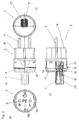
- FIG. 1 a shows the standardized base part 2 of the connection 1 according to the invention.
- the base part 2 has an elongated, rod-shaped shape with an opening at the end 25 to accommodate the respective adapter part adapted to the special requirements.
- a threaded ring 7 which is held captive on the base part 2, is provided for establishing a connection to the respective adapter part.
- a threaded ring 7 which is held captive on the base part 2
- sockets 20 which are electrically connected to the individual main conductors 26 and which, as is apparent from FIG. 1b, each contain a so-called lamella basket 12.
- Each socket 20 is in turn firmly connected to an insert part 24 common to all sockets 20, the latter being fixedly mounted on the housing of the base part 2.
- the individual bushes 20 containing the respective lamella basket 12 run parallel to the longitudinal axis of the base part 2 in the direction of the opening 25 thereof.
- the sockets 20 of the base part 2 are surrounded within the same by a wall which, viewed from the opening 25 of the base part, forms a recess 19 in which the sockets 20 are arranged longitudinally.
- the housing of the base part 2 is attached in two parts, the two parts being screwed together.
- a circumferential projection 13 is provided in the area of the opening 25 and serves to receive a complementary shoulder 14 (see FIG. 2b for example) on the respective adapter part.
- the adapter part 3 for use in the base part 2 according to FIG. 1, here in the form of a Schuko plug.
- the adapter part 3 comprises a standardized housing 17 and an insert 18 which can be inserted into the open end face of the housing 17 and contains the plug contacts 9 which are adapted to different countries.
- a plurality of contact pins 10 are provided, which are anchored with their plug-in projections 15 in the housing 17 of the adapter part 3.
- An electrical contact to the plug contacts 9 is produced via wires (not shown) struck on the plug-in lugs 15.
- the contact pins 10 are surrounded by a projection 11 which is only partially open on the front side, a corresponding channel 23 being assigned to each contact pin 10 according to FIG. 2 c).
- the projection 11 and the housing 17 are integrally formed. There is a thread 8 on the outside of the housing 17.
- the insert 18 shown in FIGS. 2b and d) can be designed differently according to the requirements.
- the lamellar baskets 12 offer good contact with the respective one Contact pin 10.
- the projection 11 on the one hand provides protection against contact with a conductor or contact pin 10 and on the other hand avoids sparking in the event of voltage peaks.
- a control button 22 for the electronics of the connection is also provided in the area of the base part 2.
- the switch is located on the end of a recessed grip 21 arranged in the base part 2 facing the adapter part 3.
- connection 1 To assemble the connection 1, it is only necessary to insert the respective adapter part 3 into the front recess of the base part 2 and to tighten the threaded ring 7. This ensures a connection that can be carried out quickly but is also secure on the one hand.
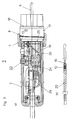
- FIG. 5a-d show adapter parts 3 - 6 adapted to the respective operating conditions (country-specific network systems). Furthermore, the illustration in FIG. 5a shows an adapter part 4 with a test probe as a plug contact 9.
- the individual, different adapter parts shown in FIG. 5 each have a uniform, standardized housing 17, in the open end of which the respective country-specific or purpose-specific use 18 is housed.
- the adapter part 4 with the test tip is also provided with a cable (27) which is led out to the side and at the free end of which a further measuring sensor is arranged.
- the invention brings about a considerable saving in production costs on the one hand and significantly improved possible uses of such generic connections on the other. It therefore represents a very special contribution in the relevant technical field.
Landscapes
- Physics & Mathematics (AREA)
- General Physics & Mathematics (AREA)
- Details Of Connecting Devices For Male And Female Coupling (AREA)
Applications Claiming Priority (2)
| Application Number | Priority Date | Filing Date | Title |
|---|---|---|---|
| DE4322407 | 1993-07-06 | ||
| DE4322407A DE4322407C1 (de) | 1993-07-06 | 1993-07-06 | Prüf- oder Meßkopf für elektrische Prüf- und/oder Meßgeräte |
Publications (3)
| Publication Number | Publication Date |
|---|---|
| EP0633475A2 true EP0633475A2 (fr) | 1995-01-11 |
| EP0633475A3 EP0633475A3 (fr) | 1995-09-20 |
| EP0633475B1 EP0633475B1 (fr) | 2003-09-24 |
Family
ID=6492040
Family Applications (1)
| Application Number | Title | Priority Date | Filing Date |
|---|---|---|---|
| EP94110467A Expired - Lifetime EP0633475B1 (fr) | 1993-07-06 | 1994-07-05 | Adaptateur pour appareils électriques |
Country Status (2)
| Country | Link |
|---|---|
| EP (1) | EP0633475B1 (fr) |
| DE (2) | DE4322407C1 (fr) |
Cited By (2)
| Publication number | Priority date | Publication date | Assignee | Title |
|---|---|---|---|---|
| DE19601562A1 (de) * | 1996-01-17 | 1997-07-24 | Whitaker Corp | Anordnung zur elektrischen Überprüfung des Verbindens zweier Teile, Verwendung einer solchen Anordnung und Kontakt insbesondere zur Verwendung in einer solchen Anordnung |
| CN103353540A (zh) * | 2013-06-27 | 2013-10-16 | 国家电网公司 | 一种用于测试光伏汇流箱测量板模块的测试装置 |
Family Cites Families (7)
| Publication number | Priority date | Publication date | Assignee | Title |
|---|---|---|---|---|
| DE2152682A1 (de) * | 1971-10-22 | 1973-04-26 | Metrawatt Gmbh | Messpitze |
| EP0128472A2 (fr) * | 1983-06-03 | 1984-12-19 | Litton Systems, Inc. | Connecteur moulé réparable sur le lieu de travail |
| DE3421880A1 (de) * | 1984-06-13 | 1985-12-19 | Brown, Boveri & Cie Ag, 6800 Mannheim | Messgeraet zur ueberpruefung der schutzmassnahmen in elektrischen anlagen |
| DE3600934A1 (de) * | 1986-01-15 | 1987-07-16 | Ralf Balik | Messadapter zum messen elektrischer groessen |
| DE3625675C2 (de) * | 1986-07-29 | 1995-11-16 | Festo Kg | Elektrischer Stecker für Magnetspulen |
| US4815983A (en) * | 1987-11-13 | 1989-03-28 | International Business Machines Corporation | Customizable plugs for A.C. power cords |
| US4904195A (en) * | 1988-06-24 | 1990-02-27 | Michael Thackeray | Twist-lock female-male plug adapter |
-
1993
- 1993-07-06 DE DE4322407A patent/DE4322407C1/de not_active Expired - Lifetime
-
1994
- 1994-07-05 DE DE59410326T patent/DE59410326D1/de not_active Expired - Lifetime
- 1994-07-05 EP EP94110467A patent/EP0633475B1/fr not_active Expired - Lifetime
Cited By (3)
| Publication number | Priority date | Publication date | Assignee | Title |
|---|---|---|---|---|
| DE19601562A1 (de) * | 1996-01-17 | 1997-07-24 | Whitaker Corp | Anordnung zur elektrischen Überprüfung des Verbindens zweier Teile, Verwendung einer solchen Anordnung und Kontakt insbesondere zur Verwendung in einer solchen Anordnung |
| CN103353540A (zh) * | 2013-06-27 | 2013-10-16 | 国家电网公司 | 一种用于测试光伏汇流箱测量板模块的测试装置 |
| CN103353540B (zh) * | 2013-06-27 | 2016-01-20 | 国家电网公司 | 一种用于测试光伏汇流箱测量板模块的测试装置 |
Also Published As
| Publication number | Publication date |
|---|---|
| EP0633475A3 (fr) | 1995-09-20 |
| DE4322407C1 (de) | 1995-01-26 |
| DE59410326D1 (de) | 2003-10-30 |
| EP0633475B1 (fr) | 2003-09-24 |
Similar Documents
| Publication | Publication Date | Title |
|---|---|---|
| DE10045498C5 (de) | Elektrische Reihenklemme | |
| EP1251590B1 (fr) | Borne électrique | |
| EP2366212B1 (fr) | Distributeur électrique multiple | |
| DE20014987U1 (de) | Universeller elektrischer Adapter | |
| DE102015121057A1 (de) | Elektrische Klemme | |
| DE102012109869B3 (de) | Montageanordnung mit einem Stromwandler und Messanordnung | |
| DE10139202B4 (de) | Elektrischer Verteiler | |
| EP4443657A1 (fr) | Connecteur modulaire | |
| EP0621483A1 (fr) | Connecteur de test pour borne de raccordement | |
| DE4322407C1 (de) | Prüf- oder Meßkopf für elektrische Prüf- und/oder Meßgeräte | |
| DE3308492A1 (de) | Mehrpolige steckverbindung | |
| EP3066720B1 (fr) | Connecteur électrique muni d'une borne à capot taraudé | |
| DE10304480B4 (de) | Anschlussklemmvorrichtung zum Anschluss eines Ringkabelschuhs und zugehöriges elektrisches Gerät | |
| DE19606050C2 (de) | Elektrischer Steckverbinder mit einem zweiteiligen, abgeschirmten Isoliergehäuse | |
| EP1289085B1 (fr) | Module enfichable pour distributeur moyenne tension | |
| DE2606917C3 (de) | Elektrischer Koaxialsteckverbinder | |
| EP1414117B1 (fr) | Arrangement d'un connecteur avec deux fiches différentes adaptées à deux différents types de prises | |
| EP0252218A1 (fr) | Raccord pour deux câbles coaxiaux | |
| DE2528487C2 (de) | Rastende Steckverbindung | |
| DE3136603C2 (de) | Elektrischer Steckverbinder | |
| DE19915637A1 (de) | Steckverbindung für Bordnetze von Kraftfahrzeugen | |
| DE3808335C2 (fr) | ||
| DE102023114105A1 (de) | Kontakteinrichtung für einen steckverbinder und steckverbinder mit zumindest einer kontakteinrichtung | |
| DE102005024440B3 (de) | Kabelanschlußbauteil für eine Kabelanschlußeinrichtung | |
| DE19508640C1 (de) | Prüfspitze |
Legal Events
| Date | Code | Title | Description |
|---|---|---|---|
| PUAI | Public reference made under article 153(3) epc to a published international application that has entered the european phase |
Free format text: ORIGINAL CODE: 0009012 |
|
| AK | Designated contracting states |
Kind code of ref document: A2 Designated state(s): CH DE GB IT LI |
|
| PUAL | Search report despatched |
Free format text: ORIGINAL CODE: 0009013 |
|
| AK | Designated contracting states |
Kind code of ref document: A3 Designated state(s): CH DE GB IT LI |
|
| 17P | Request for examination filed |
Effective date: 19960130 |
|
| 17Q | First examination report despatched |
Effective date: 20000515 |
|
| GRAH | Despatch of communication of intention to grant a patent |
Free format text: ORIGINAL CODE: EPIDOS IGRA |
|
| GRAH | Despatch of communication of intention to grant a patent |
Free format text: ORIGINAL CODE: EPIDOS IGRA |
|
| GRAA | (expected) grant |
Free format text: ORIGINAL CODE: 0009210 |
|
| AK | Designated contracting states |
Kind code of ref document: B1 Designated state(s): CH DE GB IT LI |
|
| REG | Reference to a national code |
Ref country code: GB Ref legal event code: FG4D Free format text: NOT ENGLISH |
|
| REG | Reference to a national code |
Ref country code: CH Ref legal event code: EP |
|
| REF | Corresponds to: |
Ref document number: 59410326 Country of ref document: DE Date of ref document: 20031030 Kind code of ref document: P |
|
| GBT | Gb: translation of ep patent filed (gb section 77(6)(a)/1977) |
Effective date: 20040112 |
|
| PLBE | No opposition filed within time limit |
Free format text: ORIGINAL CODE: 0009261 |
|
| STAA | Information on the status of an ep patent application or granted ep patent |
Free format text: STATUS: NO OPPOSITION FILED WITHIN TIME LIMIT |
|
| 26N | No opposition filed |
Effective date: 20040625 |
|
| PGFP | Annual fee paid to national office [announced via postgrant information from national office to epo] |
Ref country code: DE Payment date: 20130731 Year of fee payment: 20 Ref country code: CH Payment date: 20130723 Year of fee payment: 20 |
|
| PGFP | Annual fee paid to national office [announced via postgrant information from national office to epo] |
Ref country code: GB Payment date: 20130723 Year of fee payment: 20 |
|
| PGFP | Annual fee paid to national office [announced via postgrant information from national office to epo] |
Ref country code: IT Payment date: 20130730 Year of fee payment: 20 |
|
| REG | Reference to a national code |
Ref country code: DE Ref legal event code: R071 Ref document number: 59410326 Country of ref document: DE |
|
| REG | Reference to a national code |
Ref country code: CH Ref legal event code: PL |
|
| REG | Reference to a national code |
Ref country code: GB Ref legal event code: PE20 Expiry date: 20140704 |
|
| PG25 | Lapsed in a contracting state [announced via postgrant information from national office to epo] |
Ref country code: DE Free format text: LAPSE BECAUSE OF EXPIRATION OF PROTECTION Effective date: 20140708 |
|
| PG25 | Lapsed in a contracting state [announced via postgrant information from national office to epo] |
Ref country code: GB Free format text: LAPSE BECAUSE OF EXPIRATION OF PROTECTION Effective date: 20140704 |