EP0633557A1 - Dispositif de fixation des enseignes - Google Patents
Dispositif de fixation des enseignes Download PDFInfo
- Publication number
- EP0633557A1 EP0633557A1 EP94108773A EP94108773A EP0633557A1 EP 0633557 A1 EP0633557 A1 EP 0633557A1 EP 94108773 A EP94108773 A EP 94108773A EP 94108773 A EP94108773 A EP 94108773A EP 0633557 A1 EP0633557 A1 EP 0633557A1
- Authority
- EP
- European Patent Office
- Prior art keywords
- frame
- base
- frame element
- plate
- motor vehicle
- Prior art date
- Legal status (The legal status is an assumption and is not a legal conclusion. Google has not performed a legal analysis and makes no representation as to the accuracy of the status listed.)
- Granted
Links
Images

Classifications
-
- B—PERFORMING OPERATIONS; TRANSPORTING
- B60—VEHICLES IN GENERAL
- B60R—VEHICLES, VEHICLE FITTINGS, OR VEHICLE PARTS, NOT OTHERWISE PROVIDED FOR
- B60R13/00—Elements for body-finishing, identifying, or decorating; Arrangements or adaptations for advertising purposes
- B60R13/10—Registration, licensing, or like devices
- B60R13/105—Licence- or registration plates, provided with mounting means, e.g. frames, holders, retainers, brackets
-
- G—PHYSICS
- G09—EDUCATION; CRYPTOGRAPHY; DISPLAY; ADVERTISING; SEALS
- G09F—DISPLAYING; ADVERTISING; SIGNS; LABELS OR NAME-PLATES; SEALS
- G09F15/00—Boards, hoardings, pillars, or like structures for notices, placards, posters, or the like
- G09F15/0006—Boards, hoardings, pillars, or like structures for notices, placards, posters, or the like planar structures comprising one or more panels
- G09F15/0018—Boards, hoardings, pillars, or like structures for notices, placards, posters, or the like planar structures comprising one or more panels panel clamping or fastening means
Definitions
- the invention relates to a device for holding signs, in particular type plates and number plates, on an object, in particular a motor vehicle.
- Devices of this type are also called fastenings for license plates.
- the known brackets are usually made up of several parts, consisting of at least two parts.
- a lockable holder for motor vehicle license plates is already known (DE-A1-24 35 961), which is constructed from a plate which can be screwed onto a motor vehicle and a frame which is hinged to the plate via a hinge. The frame is screwed onto the plate to close the bracket.
- a device for fastening a board to a base which consists of a base plate and a frame hinged to it via a film hinge. To close the frame, it is closed and engages in an elongated hole with a barbed pin. A tool must be used to open it, which can only be inserted from the back of the base plate.
- the invention has for its object to provide a device of the type mentioned, which can be used without difficulty even in confined spaces, as can occur in modern motor vehicles.
- the invention proposes a device with the features of claim 1. Further training is the subject of the subclaims.
- the frame element which in particular covers the edge area of the sign to be fastened, makes it possible in its release position to insert the sign directly from the front on a vertical base.
- the device according to the invention can still be used in motor vehicles in which the space for the license plate is recessed and is therefore surrounded on all sides by an elevation.
- the invention proposes that the frame element forms a closed frame in its locked position.
- the sign is therefore covered and held along its entire edge in the edge area.
- the frame element is a separate element from the base. It can then be inserted and locked from the front.
- the frame element is pivotably articulated on the base in the region of a side edge thereof. In this case, the release position is that the frame element is swung open and thus releases access. After inserting the license plate, the frame element can then be pivoted onto the base and locked there.
- two frame elements are provided, each of which is then only intended for part of the circumference of the shield.
- the two frame elements are articulated on opposite side edges of the base.
- the locking device can be designed such that in the case of a plurality of frame elements, one frame element can be locked to the base, while the second frame element can be locked to the first frame element.
- the invention proposes that the locking device can be released by hand when the plate-like base is not yet attached to the motor vehicle, i.e. without the help of a tool. This makes it possible to assemble the factory-made device after it is manufactured, so that it takes up less space and takes a more stable state. Before being attached to the motor vehicle, the fitter can easily and simply bring the holder into its release position.
- the locking device when the plate-like support is screwed to the motor vehicle, the locking device can only be released with the aid of a tool, in particular a special tool. Misuse can thus be prevented.
- a particularly simple way of realizing this type of locking device is that the locking device is easily accessible from the underside of the base. This underside is no longer accessible when attached to the motor vehicle. The release can then be carried out from the opposite front using a special tool. This can happen, for example, in that several tongues have to be inserted through small openings at the same time.
- the invention proposes that the device is injection molded in one piece from plastic, and the pivot connection between the frame elements and the base can be realized by means of film hinges.
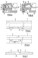
- FIG. 1 shows in the left half a front view of a device according to the invention in the open state, ie the position in which the license plate can be inserted into the device, while the right half of FIG. 1 shows the front view of the device in the closed state, but without the license plate shows.
- the device contains a plate-shaped base 1, which has approximately the shape of a license plate for a motor vehicle.
- the pad is slightly larger on all sides. It has an elongated rectangular shape with rounded corners.
- the pad contains some reinforcement webs 2, which form a reinforcement of the pad.
- a frame element 6, 7 is pivotally articulated on the base at the edge area thereof by means of film hinges 5, of which FIG. 1 each shows two.
- the frame elements have a certain width and, in the assembled state, see a closed rectangular frame in FIG. 1 on the right.
- each frame element is approximately U-shaped and is formed by two legs 8, 9 which are integrally connected to one another by a web 10.
- the two free ends 11 of one frame element are provided on their inside with a tab 12 which, when folded, comes to rest under the web 10 of the free end 13 of the other frame element 6.
- the one frame element 6 on the inside of its outer leg 8 has three nose-like projections 14, 15, 16 which engage in correspondingly shaped counter-projections in an incision 17 in the outer edge of the plate-like base 1. These projections form a lock for the one frame element 6 with the base 1.
- Fig. 2 shows an enlarged section along line II-II in Fig. 1.
- line II-II in Fig. 1.
- dash-dotted lines also show the frame element 6 in the closed state.
- the plate-like base has an edge region 19 which is flush with the upper side 18 of the stiffening webs 2 and is delimited on all sides by a circumferential raised flange 20.
- a bearing surface for the number plate 21, indicated by dash-dotted lines, is created by the edge region 19 and the upper side 18 of the reinforcing webs 2.
- an edge region 22 is formed at the same height, the width of which corresponds to the thickness of the outer leg 8 of the frame part 6.
- the number plate 21 is inserted into the space inside the flange 20 and then the frame element 7 provided with the tab 12 is first closed until it lies on the edge region 22 of the base 1. Then the upper frame element 6 is pivoted and closed until it is locked with its projections 14 to 16 on the base. In this state, the license plate 21 is fixed. Its edge bead 23 lies between the legs 8 and 9 of the frame element 6 and 7, respectively.
- a nose 24 can also be formed on the inside of the web 13, which leads to a further improved fixing of the number plate 21. This nose can also be designed as a continuous profile.
- FIG. 7 The side view of the closed device is shown in FIG. 7, to which reference is first made.
- a projection 25 engaging in the incision 17 of the base 1 is formed on the frame element 6, in the area of its free end 13, a projection 25 engaging in the incision 17 of the base 1 is formed.
- This projection 25 is in different places can be seen in section in FIGS. 3 and 4.
- FIG. 3 first shows the section at the height of the first or third projection 14, while FIG. 4 shows a section through the middle projection 15.
- the outer edge 26 of the base 1 has a projection at the point in FIG. 3, which is formed by an inclined surface at the top and bottom.
- the end of the projection 25 is provided on the inside with a correspondingly shaped wedge surface 27.
- a cavity 28 is formed behind the outer edge 26 and opens out on the rear side 29 of the base 1.
- a narrow opening 30 is provided in the web part 10 of the frame element. If you push a pin through the opening 30 against the upper wedge surface 31, pushing it further pivots the projection 25 to the left in FIG. 3 until its lower wedge surface 27 comes out of engagement with the counter surface of the outer edge 26. Since a second projection 16 of this type is arranged at a distance from the projection 14 with its wedge surface 27, inserting a pin into the opening 30 alone is not sufficient to bring the edge region 25 out of engagement with the edge region 26.
- the projection 15 is arranged in the middle between the two identically designed projections 14 and 16, see FIG. 4.
- the projection 15 has a barb shape with a surface 31 running perpendicular to the outside, which engages behind a surface 32 which also runs vertically.
- the outer edge 26 is interrupted in this area, so that the rear of the projection 25 and the two surfaces 31, 32 mentioned are accessible from the cavity 28.
- the projection 15 can be pressed outwards by hand.
- FIG. 5 shows the top view of the edge area of the base 1 in the area of the incision 17.
- the inclined surfaces 33 for the projections 14 and 16 can be seen, while in the middle the area with the straight surface 32 can be seen on the underside.
- the course of both frame elements 6, 7 is shown in dash-dotted lines in FIG. 5.
- Fig. 6 shows the incision 17 from the side. Again, the two frame elements 6, 7 are shown in dash-dotted lines.
- the separating surface 34 between the frame element 6 and the frame element 7 also runs obliquely, so that here too there is a locking between the two frame elements.
- a resilient element 36 is shown delimited by a slot 35 in the lower left region of the base 1.
- the action can ensure that when inserting the above-mentioned special tool into the two openings 30 after pivoting the projection 25 outwards, as soon as the projection 15 disengages, the spring action then opens the two frame elements by itself.
- individual peg-like projections 37 can be formed on the inside of the frame elements 6, 7, which engage in corresponding recesses 38 in the base 1.
- the reverse training is of course also possible.
- the device has so far been described for holding signs, in particular number plates, on motor vehicles. Of course, it is also possible to hold other signs, type plates, etc. on other objects, for example for marking reserved parking spaces or also for marking machines and buildings.
- the pad is attached through holes in the pad, which are then covered by the sign itself when the sign is inserted. For the sake of simplicity, the term shield is always used.
Landscapes
- Engineering & Computer Science (AREA)
- Mechanical Engineering (AREA)
- Physics & Mathematics (AREA)
- General Physics & Mathematics (AREA)
- Theoretical Computer Science (AREA)
- Vehicle Waterproofing, Decoration, And Sanitation Devices (AREA)
- Gripping On Spindles (AREA)
- Road Signs Or Road Markings (AREA)
- Liquid Crystal (AREA)
- Jigs For Machine Tools (AREA)
- Apparatus For Radiation Diagnosis (AREA)
- Control Of Vending Devices And Auxiliary Devices For Vending Devices (AREA)
- Load-Engaging Elements For Cranes (AREA)
- Telephone Function (AREA)
- Paper (AREA)
- Fittings On The Vehicle Exterior For Carrying Loads, And Devices For Holding Or Mounting Articles (AREA)
- Vending Machines For Individual Products (AREA)
- Branching, Merging, And Special Transfer Between Conveyors (AREA)
- Formation And Processing Of Food Products (AREA)
Applications Claiming Priority (2)
| Application Number | Priority Date | Filing Date | Title |
|---|---|---|---|
| DE9310156U | 1993-07-08 | ||
| DE9310156U DE9310156U1 (de) | 1993-07-08 | 1993-07-08 | Vorrichtung zur Halterung von Schildern |
Publications (2)
| Publication Number | Publication Date |
|---|---|
| EP0633557A1 true EP0633557A1 (fr) | 1995-01-11 |
| EP0633557B1 EP0633557B1 (fr) | 1997-08-20 |
Family
ID=6895319
Family Applications (1)
| Application Number | Title | Priority Date | Filing Date |
|---|---|---|---|
| EP94108773A Expired - Lifetime EP0633557B1 (fr) | 1993-07-08 | 1994-06-08 | Dispositif de fixation des enseignes |
Country Status (8)
| Country | Link |
|---|---|
| EP (1) | EP0633557B1 (fr) |
| AT (1) | ATE157186T1 (fr) |
| DE (2) | DE9310156U1 (fr) |
| DK (1) | DK0633557T3 (fr) |
| ES (1) | ES2105421T3 (fr) |
| FI (1) | FI943262A7 (fr) |
| GR (1) | GR3025350T3 (fr) |
| NO (1) | NO942448L (fr) |
Cited By (1)
| Publication number | Priority date | Publication date | Assignee | Title |
|---|---|---|---|---|
| DE202019001864U1 (de) | 2019-04-27 | 2019-06-19 | Hoheisel Engineering GmbH | Kennzeichenhalter für Kraftfahrzeug-Kennzeichen mit Diebstahlsicherung |
Families Citing this family (5)
| Publication number | Priority date | Publication date | Assignee | Title |
|---|---|---|---|---|
| DE202006006935U1 (de) * | 2006-04-29 | 2006-06-29 | Heeks, Karl-Heinz | Halterung für eine KFZ-Kennzeichen-Platte |
| FR2930217B1 (fr) * | 2008-04-18 | 2010-06-18 | Renault Sas | Dispositif de fixation d'une plaque sur un vehicule automobile et bouclier de vehicule automobile comportant un tel dispositif. |
| DE102015215319C5 (de) | 2015-08-11 | 2021-11-25 | Adolf Würth Gmbh & Co Kg | Vorrichtung zum Halten eines Schilds |
| DE102018001842A1 (de) * | 2018-03-05 | 2019-09-05 | Karl Rodewald | Montageanordnung für ein amtliches Kennzeichen an einem Kraftfahrzeug sowie Grundplatte für eine solche Montageanordnung |
| IT202200002174A1 (it) * | 2022-02-07 | 2023-08-07 | Rizoma S R L | Supporto per targa di veicolo |
Citations (3)
| Publication number | Priority date | Publication date | Assignee | Title |
|---|---|---|---|---|
| DE8910590U1 (de) * | 1988-09-08 | 1989-10-19 | Marksteiner, Heinz, Wien | Vorrichtung zur Befestigung einer Tafel an einer Unterlage |
| DE3821762A1 (de) * | 1988-06-28 | 1990-01-11 | Josef Moeschl | Kennzeichen-halter |
| DE9111675U1 (de) * | 1991-09-19 | 1992-10-29 | Weigel, Hans, 7134 Knittlingen | Verschlußleiste aus Kunststoff für Autoschilderbefestigungen an Kraftfahrzeugen |
Family Cites Families (9)
| Publication number | Priority date | Publication date | Assignee | Title |
|---|---|---|---|---|
| GB1226542A (fr) * | 1967-04-07 | 1971-03-31 | ||
| US3702510A (en) * | 1970-09-17 | 1972-11-14 | Ford Motor Co | License plate support and pivotable cover member |
| DE2435961A1 (de) * | 1974-07-26 | 1976-02-19 | Ernst Karl Haut | Verschliessbare halterung fuer schilder und kraftfahrzeugkennzeichen |
| GB8331975D0 (en) * | 1983-11-30 | 1984-01-04 | Parkes A E | Housing for number plate |
| AT380842B (de) * | 1984-08-24 | 1986-07-10 | Evam Eva Marksteiner Vertrieb | Vorrichtung zur befestigung einer tafel an einer unterlage |
| DE8600110U1 (de) * | 1986-01-04 | 1986-02-27 | Weigel, Hans, 7538 Keltern | Verstärkungsunterlagen aus Kunststoff für KFZ-Kennzeichen |
| DE8702654U1 (de) * | 1987-02-20 | 1987-07-09 | Anton Rathgeber GmbH & Co KG, 8024 Oberhaching | Leiste mit einer Werbefläche zur Anbringung im Randbereich eines Kfz-Kennzeichens |
| DE8716019U1 (de) * | 1987-12-04 | 1988-01-28 | Adolf Würth GmbH & Co KG, 7118 Künzelsau | Halterung für Schilder |
| DE4006213A1 (de) * | 1990-02-28 | 1991-08-29 | Thomas Walz | Vorrichtung zur aufnahme eines tafelelements |
-
1993
- 1993-07-08 DE DE9310156U patent/DE9310156U1/de not_active Expired - Lifetime
-
1994
- 1994-06-08 DE DE59403773T patent/DE59403773D1/de not_active Expired - Lifetime
- 1994-06-08 EP EP94108773A patent/EP0633557B1/fr not_active Expired - Lifetime
- 1994-06-08 AT AT94108773T patent/ATE157186T1/de active
- 1994-06-08 DK DK94108773.6T patent/DK0633557T3/da active
- 1994-06-08 ES ES94108773T patent/ES2105421T3/es not_active Expired - Lifetime
- 1994-06-29 NO NO942448A patent/NO942448L/no unknown
- 1994-07-08 FI FI943262A patent/FI943262A7/fi unknown
-
1997
- 1997-11-12 GR GR970402991T patent/GR3025350T3/el unknown
Patent Citations (3)
| Publication number | Priority date | Publication date | Assignee | Title |
|---|---|---|---|---|
| DE3821762A1 (de) * | 1988-06-28 | 1990-01-11 | Josef Moeschl | Kennzeichen-halter |
| DE8910590U1 (de) * | 1988-09-08 | 1989-10-19 | Marksteiner, Heinz, Wien | Vorrichtung zur Befestigung einer Tafel an einer Unterlage |
| DE9111675U1 (de) * | 1991-09-19 | 1992-10-29 | Weigel, Hans, 7134 Knittlingen | Verschlußleiste aus Kunststoff für Autoschilderbefestigungen an Kraftfahrzeugen |
Cited By (1)
| Publication number | Priority date | Publication date | Assignee | Title |
|---|---|---|---|---|
| DE202019001864U1 (de) | 2019-04-27 | 2019-06-19 | Hoheisel Engineering GmbH | Kennzeichenhalter für Kraftfahrzeug-Kennzeichen mit Diebstahlsicherung |
Also Published As
| Publication number | Publication date |
|---|---|
| GR3025350T3 (en) | 1998-02-27 |
| ES2105421T3 (es) | 1997-10-16 |
| DE59403773D1 (de) | 1997-09-25 |
| ATE157186T1 (de) | 1997-09-15 |
| EP0633557B1 (fr) | 1997-08-20 |
| FI943262L (fi) | 1995-01-09 |
| NO942448L (no) | 1995-01-09 |
| DE9310156U1 (de) | 1993-09-02 |
| FI943262A7 (fi) | 1995-01-09 |
| DK0633557T3 (da) | 1998-04-06 |
| FI943262A0 (fi) | 1994-07-08 |
| NO942448D0 (no) | 1994-06-29 |
Similar Documents
| Publication | Publication Date | Title |
|---|---|---|
| CH641533A5 (de) | Vorrichtung zur loesbaren befestigung eines flexiblen teils an einem starren teil, insbesondere einer blache an einem fahrzeug. | |
| DE2412114A1 (de) | Vorrichtung zum verriegeln bestimmter von mehreren herausziehbaren aufbewahrungseinheiten bei einer aufbewahrungseinrichtung, z.b. einem schrank | |
| DE2735787A1 (de) | Fuehrungselement fuer nachgiebig zu lagernde schiebetuerelemente sowie damit ausgeruestetes schiebetuerelement | |
| DE20015913U1 (de) | Steckverbinder für Hohlprofile | |
| DE69013555T2 (de) | Behälter zum Unterbringen von elektrischen Apparaten. | |
| EP0633557B1 (fr) | Dispositif de fixation des enseignes | |
| CH642712A5 (de) | Schiebetuerfluegel mit verstellbaren rollentraegern. | |
| EP3727088B1 (fr) | Paroi latérale de tiroir | |
| DE60035224T2 (de) | Verriegelungsvorrichtung und verfahren zu deren herstellung | |
| DE19527692C2 (de) | Vorrichtung zur Aufnahme eines Tafelelements | |
| EP0217268A2 (fr) | Elément de plafond rectangulaire pour un faux plafond | |
| EP0658867A2 (fr) | Clip de marquage de câble | |
| DE3145203A1 (de) | Kassette zur aufnahme von langgestreckten gegenstaenden | |
| DE19511059C2 (de) | Einbruchsichere Profileinheit, bestehend aus zwei Profilen | |
| DE102008039964B3 (de) | Vorrichtung zur Aufnahme eines Tafelelements | |
| DE68907970T2 (de) | Konstruktion zum Tragen eines grossen Spiegels und ein grosser Spiegel, der diese Konstruktion hat. | |
| DE20219460U1 (de) | Kassette | |
| DE202018102561U1 (de) | Kassettenstapel aus einzelnen Kassetten, vorzugsweise zur Aufnahme von Präparaten für Laboranalysen | |
| DE29707969U1 (de) | Verkleidung für einen Flachheizkörper | |
| DE69807401T2 (de) | Sockel für Kabelkanal mit einem V-förmigen Querschnitt, insbesondere Eckkanal oder Unterputzkanal | |
| DE29812410U1 (de) | Befestigungsvorrichtung für ein Dekorelement sowie damit versehenes Dekorelement | |
| EP0384214B1 (fr) | Porte coulissante pour cabines de douche III | |
| WO2024189070A1 (fr) | Étiquette inscriptible avec support de maintien relié à celle-ci | |
| DE102005046091A1 (de) | Kennzeichnungsvorrichtung für Fahrzeuge | |
| EP3957816A1 (fr) | Rideau roulant |
Legal Events
| Date | Code | Title | Description |
|---|---|---|---|
| PUAI | Public reference made under article 153(3) epc to a published international application that has entered the european phase |
Free format text: ORIGINAL CODE: 0009012 |
|
| AK | Designated contracting states |
Kind code of ref document: A1 Designated state(s): AT BE CH DE DK ES FR GB GR IE IT LI LU MC NL PT SE |
|
| 17P | Request for examination filed |
Effective date: 19950414 |
|
| 17Q | First examination report despatched |
Effective date: 19960326 |
|
| GRAG | Despatch of communication of intention to grant |
Free format text: ORIGINAL CODE: EPIDOS AGRA |
|
| GRAH | Despatch of communication of intention to grant a patent |
Free format text: ORIGINAL CODE: EPIDOS IGRA |
|
| GRAH | Despatch of communication of intention to grant a patent |
Free format text: ORIGINAL CODE: EPIDOS IGRA |
|
| GRAA | (expected) grant |
Free format text: ORIGINAL CODE: 0009210 |
|
| AK | Designated contracting states |
Kind code of ref document: B1 Designated state(s): AT BE CH DE DK ES FR GB GR IE IT LI LU MC NL PT SE |
|
| REF | Corresponds to: |
Ref document number: 157186 Country of ref document: AT Date of ref document: 19970915 Kind code of ref document: T |
|
| REG | Reference to a national code |
Ref country code: CH Ref legal event code: NV Representative=s name: TROESCH SCHEIDEGGER WERNER AG Ref country code: CH Ref legal event code: EP |
|
| GBT | Gb: translation of ep patent filed (gb section 77(6)(a)/1977) |
Effective date: 19970820 |
|
| RAP2 | Party data changed (patent owner data changed or rights of a patent transferred) |
Owner name: ADOLF WUERTH GMBH & CO. KG |
|
| REF | Corresponds to: |
Ref document number: 59403773 Country of ref document: DE Date of ref document: 19970925 |
|
| REG | Reference to a national code |
Ref country code: ES Ref legal event code: FG2A Ref document number: 2105421 Country of ref document: ES Kind code of ref document: T3 |
|
| ET | Fr: translation filed | ||
| NLT2 | Nl: modifications (of names), taken from the european patent patent bulletin |
Owner name: ADOLF WUERTH GMBH & CO. KG |
|
| ITF | It: translation for a ep patent filed | ||
| REG | Reference to a national code |
Ref country code: PT Ref legal event code: SC4A Free format text: AVAILABILITY OF NATIONAL TRANSLATION Effective date: 19970821 |
|
| REG | Reference to a national code |
Ref country code: GR Ref legal event code: FG4A Free format text: 3025350 |
|
| REG | Reference to a national code |
Ref country code: DK Ref legal event code: T3 |
|
| PGFP | Annual fee paid to national office [announced via postgrant information from national office to epo] |
Ref country code: IE Payment date: 19980527 Year of fee payment: 5 Ref country code: GB Payment date: 19980527 Year of fee payment: 5 |
|
| PGFP | Annual fee paid to national office [announced via postgrant information from national office to epo] |
Ref country code: PT Payment date: 19980529 Year of fee payment: 5 |
|
| PGFP | Annual fee paid to national office [announced via postgrant information from national office to epo] |
Ref country code: FR Payment date: 19980617 Year of fee payment: 5 |
|
| PGFP | Annual fee paid to national office [announced via postgrant information from national office to epo] |
Ref country code: SE Payment date: 19980623 Year of fee payment: 5 Ref country code: BE Payment date: 19980623 Year of fee payment: 5 Ref country code: AT Payment date: 19980623 Year of fee payment: 5 |
|
| PGFP | Annual fee paid to national office [announced via postgrant information from national office to epo] |
Ref country code: ES Payment date: 19980624 Year of fee payment: 5 Ref country code: DK Payment date: 19980624 Year of fee payment: 5 |
|
| PGFP | Annual fee paid to national office [announced via postgrant information from national office to epo] |
Ref country code: NL Payment date: 19980625 Year of fee payment: 5 |
|
| PLBE | No opposition filed within time limit |
Free format text: ORIGINAL CODE: 0009261 |
|
| STAA | Information on the status of an ep patent application or granted ep patent |
Free format text: STATUS: NO OPPOSITION FILED WITHIN TIME LIMIT |
|
| PGFP | Annual fee paid to national office [announced via postgrant information from national office to epo] |
Ref country code: MC Payment date: 19980630 Year of fee payment: 5 Ref country code: GR Payment date: 19980630 Year of fee payment: 5 |
|
| PGFP | Annual fee paid to national office [announced via postgrant information from national office to epo] |
Ref country code: CH Payment date: 19980701 Year of fee payment: 5 |
|
| PGFP | Annual fee paid to national office [announced via postgrant information from national office to epo] |
Ref country code: LU Payment date: 19980804 Year of fee payment: 5 |
|
| 26N | No opposition filed | ||
| PG25 | Lapsed in a contracting state [announced via postgrant information from national office to epo] |
Ref country code: LU Free format text: LAPSE BECAUSE OF NON-PAYMENT OF DUE FEES Effective date: 19990608 Ref country code: IE Free format text: LAPSE BECAUSE OF NON-PAYMENT OF DUE FEES Effective date: 19990608 Ref country code: GB Free format text: LAPSE BECAUSE OF NON-PAYMENT OF DUE FEES Effective date: 19990608 Ref country code: AT Free format text: LAPSE BECAUSE OF NON-PAYMENT OF DUE FEES Effective date: 19990608 |
|
| PG25 | Lapsed in a contracting state [announced via postgrant information from national office to epo] |
Ref country code: ES Free format text: LAPSE BECAUSE OF EXPIRATION OF PROTECTION Effective date: 19990609 |
|
| PG25 | Lapsed in a contracting state [announced via postgrant information from national office to epo] |
Ref country code: SE Free format text: THE PATENT HAS BEEN ANNULLED BY A DECISION OF A NATIONAL AUTHORITY Effective date: 19990629 |
|
| PG25 | Lapsed in a contracting state [announced via postgrant information from national office to epo] |
Ref country code: LI Free format text: LAPSE BECAUSE OF NON-PAYMENT OF DUE FEES Effective date: 19990630 Ref country code: GR Free format text: LAPSE BECAUSE OF NON-PAYMENT OF DUE FEES Effective date: 19990630 Ref country code: FR Free format text: THE PATENT HAS BEEN ANNULLED BY A DECISION OF A NATIONAL AUTHORITY Effective date: 19990630 Ref country code: DK Free format text: LAPSE BECAUSE OF NON-PAYMENT OF DUE FEES Effective date: 19990630 Ref country code: CH Free format text: LAPSE BECAUSE OF NON-PAYMENT OF DUE FEES Effective date: 19990630 Ref country code: BE Free format text: LAPSE BECAUSE OF NON-PAYMENT OF DUE FEES Effective date: 19990630 |
|
| BERE | Be: lapsed |
Owner name: ADOLF WURTH G.M.B.H. & CO. K.G. Effective date: 19990630 |
|
| PG25 | Lapsed in a contracting state [announced via postgrant information from national office to epo] |
Ref country code: PT Free format text: LAPSE BECAUSE OF NON-PAYMENT OF DUE FEES Effective date: 19991231 Ref country code: MC Free format text: LAPSE BECAUSE OF NON-PAYMENT OF DUE FEES Effective date: 19991231 |
|
| PG25 | Lapsed in a contracting state [announced via postgrant information from national office to epo] |
Ref country code: NL Free format text: LAPSE BECAUSE OF NON-PAYMENT OF DUE FEES Effective date: 20000101 |
|
| GBPC | Gb: european patent ceased through non-payment of renewal fee |
Effective date: 19990608 |
|
| REG | Reference to a national code |
Ref country code: CH Ref legal event code: PL |
|
| EUG | Se: european patent has lapsed |
Ref document number: 94108773.6 |
|
| NLV4 | Nl: lapsed or anulled due to non-payment of the annual fee |
Effective date: 20000101 |
|
| REG | Reference to a national code |
Ref country code: DK Ref legal event code: EBP |
|
| REG | Reference to a national code |
Ref country code: PT Ref legal event code: MM4A Free format text: LAPSE DUE TO NON-PAYMENT OF FEES Effective date: 19991231 |
|
| REG | Reference to a national code |
Ref country code: IE Ref legal event code: MM4A |
|
| REG | Reference to a national code |
Ref country code: FR Ref legal event code: ST |
|
| REG | Reference to a national code |
Ref country code: ES Ref legal event code: FD2A Effective date: 20010601 |
|
| PG25 | Lapsed in a contracting state [announced via postgrant information from national office to epo] |
Ref country code: IT Free format text: LAPSE BECAUSE OF NON-PAYMENT OF DUE FEES;WARNING: LAPSES OF ITALIAN PATENTS WITH EFFECTIVE DATE BEFORE 2007 MAY HAVE OCCURRED AT ANY TIME BEFORE 2007. THE CORRECT EFFECTIVE DATE MAY BE DIFFERENT FROM THE ONE RECORDED. Effective date: 20050608 |
|
| PGFP | Annual fee paid to national office [announced via postgrant information from national office to epo] |
Ref country code: DE Payment date: 20120622 Year of fee payment: 19 |
|
| REG | Reference to a national code |
Ref country code: DE Ref legal event code: R119 Ref document number: 59403773 Country of ref document: DE Effective date: 20140101 |
|
| PG25 | Lapsed in a contracting state [announced via postgrant information from national office to epo] |
Ref country code: DE Free format text: LAPSE BECAUSE OF NON-PAYMENT OF DUE FEES Effective date: 20140101 |