EP0633623A2 - Microconnecteur et outil automatique pour son application - Google Patents
Microconnecteur et outil automatique pour son application Download PDFInfo
- Publication number
- EP0633623A2 EP0633623A2 EP94304349A EP94304349A EP0633623A2 EP 0633623 A2 EP0633623 A2 EP 0633623A2 EP 94304349 A EP94304349 A EP 94304349A EP 94304349 A EP94304349 A EP 94304349A EP 0633623 A2 EP0633623 A2 EP 0633623A2
- Authority
- EP
- European Patent Office
- Prior art keywords
- micro
- connector
- connectors
- application
- tool
- Prior art date
- Legal status (The legal status is an assumption and is not a legal conclusion. Google has not performed a legal analysis and makes no representation as to the accuracy of the status listed.)
- Ceased
Links
Images




Classifications
-
- H—ELECTRICITY
- H01—ELECTRIC ELEMENTS
- H01R—ELECTRICALLY-CONDUCTIVE CONNECTIONS; STRUCTURAL ASSOCIATIONS OF A PLURALITY OF MUTUALLY-INSULATED ELECTRICAL CONNECTING ELEMENTS; COUPLING DEVICES; CURRENT COLLECTORS
- H01R4/00—Electrically-conductive connections between two or more conductive members in direct contact, i.e. touching one another; Means for effecting or maintaining such contact; Electrically-conductive connections having two or more spaced connecting locations for conductors and using contact members penetrating insulation
- H01R4/24—Connections using contact members penetrating or cutting insulation or cable strands
-
- H—ELECTRICITY
- H01—ELECTRIC ELEMENTS
- H01R—ELECTRICALLY-CONDUCTIVE CONNECTIONS; STRUCTURAL ASSOCIATIONS OF A PLURALITY OF MUTUALLY-INSULATED ELECTRICAL CONNECTING ELEMENTS; COUPLING DEVICES; CURRENT COLLECTORS
- H01R43/00—Apparatus or processes specially adapted for manufacturing, assembling, maintaining, or repairing of line connectors or current collectors or for joining electric conductors
- H01R43/01—Apparatus or processes specially adapted for manufacturing, assembling, maintaining, or repairing of line connectors or current collectors or for joining electric conductors for connecting unstripped conductors to contact members having insulation cutting edges
-
- H—ELECTRICITY
- H01—ELECTRIC ELEMENTS
- H01R—ELECTRICALLY-CONDUCTIVE CONNECTIONS; STRUCTURAL ASSOCIATIONS OF A PLURALITY OF MUTUALLY-INSULATED ELECTRICAL CONNECTING ELEMENTS; COUPLING DEVICES; CURRENT COLLECTORS
- H01R4/00—Electrically-conductive connections between two or more conductive members in direct contact, i.e. touching one another; Means for effecting or maintaining such contact; Electrically-conductive connections having two or more spaced connecting locations for conductors and using contact members penetrating insulation
- H01R4/24—Connections using contact members penetrating or cutting insulation or cable strands
- H01R4/2495—Insulation penetration combined with permanent deformation of the contact member, e.g. crimping
-
- H—ELECTRICITY
- H01—ELECTRIC ELEMENTS
- H01R—ELECTRICALLY-CONDUCTIVE CONNECTIONS; STRUCTURAL ASSOCIATIONS OF A PLURALITY OF MUTUALLY-INSULATED ELECTRICAL CONNECTING ELEMENTS; COUPLING DEVICES; CURRENT COLLECTORS
- H01R43/00—Apparatus or processes specially adapted for manufacturing, assembling, maintaining, or repairing of line connectors or current collectors or for joining electric conductors
- H01R43/04—Apparatus or processes specially adapted for manufacturing, assembling, maintaining, or repairing of line connectors or current collectors or for joining electric conductors for forming connections by deformation, e.g. crimping tool
- H01R43/048—Crimping apparatus or processes
- H01R43/05—Crimping apparatus or processes with wire-insulation stripping
Definitions
- the present invention relates to electrical connecting devices employed in the splicing of multiconductor telephone cables comprised of electrical conductors of different or same gauge using only one type of connector, and to automated tools for applying the connecting device. More specifically, the present invention relates to a type of connector for splicing multiconductor telephone cables which requires a specific application tool, to crimp the connector.
- the cable ends are arranged to each other and the individual wires in the cables are spliced by the operator or lineman.
- the ends of two pairs of wires are being connected to each other, it is necessary to make two separate electrical connections, i.e., to connect each corresponding end of the wires of the two pairs.
- the lineman when the ends of a severed telephone cable are being spliced, the lineman first separates from the numerous pairs in each end the particular pairs which are to be connected. He then separates the two wires in each of the pairs and makes electrical connections between the ends of these wires. After making the connections for these pairs, he can then proceed to a next two pair of wires in the cable and make the electrical connections for it.
- Automatic tools for application of connectors of the prior art are usually of the type having a slot which extends transversely between its ends.
- the wires which should be spliced are generally positioned in the slot of the tool and then centrally cut. Further, the automatic application tool positions the wires in the connector to be used and then crimps inwardly the legs of the connector, thus accomplishing the crimping of the connector.
- the invention is a connector device designed to join 19-26 AWG copper telephone cables with PVC or paper insulation of the aerial or underground type, which uses only one type of connector comprised preferably of a copper alloy adhered to a polyester film, the metallic body of said connector being tin coated.
- the micro-connector of the present invention has a reduced size, that is approximately half of the length of the connectors of the prior art and, in addition, permits the use of a great amount of different wire gauges for the connector, in the range of four wires with different gauges.
- the application tool of the present invention applies the micro-connectors to the wires by means of the crimping of the micro-connectors between a set of crimpers.
- a Micro-connector is disclosed that is stamped on an integral piece having a parallelepipedical body in the shape of "U" comprised of a bottom portion and two sidewalls capable of being inwardly crimped.
- the bottom portion of the micro-connector is centrally hollowed out and has in its inner ends two sets of small metallic tongues located perpendicularly in relation to the bottom portion.
- the small metallic tongues are spaced apart from each other by the contact slots which are of different sizes.
- the sidewalls of the micro-connector have in an internal portion thereof a positioner rod located adjacent to the sidewalls and two legs located on the ends of each sidewall, each of the legs having two cutouts in the shape of a "V.”
- an automatic tool for application of micro-connectors having a wire cut system which cuts the wires on the side ends of the crimper of the application tool arranging them side by side after the cutting.
- the tool includes a wire positioning system which permits the application of micro-connectors for both tapping and splicing.
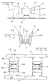
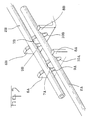
- the micro-connector 1 which permits the splicing of telephone cables 2A, 2B and 2C of the present invention is preferably made of a copper alloy adhered to a strip 3 of polyester film, the body of said micro-connector being tin coated.
- micro-connector 1 of the present invention is manufactured in an integral piece having a parallelepipedical body in the shape of a "U" 4, the bottom portion 5 of the said body in "U” being centrally hollow throughout and slightly narrower than the top portion of the micro-connector 1.
- the centrally hollow out bottom portion of said micro-connector 1 there are three small metallic tongues 6, 7 and 8 in the shape of lances perpendicularly located in relation to the bottom portion of the body in "U" 4, three of them 6A, 7A and 8A being located at a first end of the hollow out portion 5 and the other three 6B, 7B and 8B being located at the other side of the hollow out end 5.
- Said metallic small tongues 6, 7 and 8 are spaced from each other by small contact slots 9, 10 which are designed to receive the telephone cables 2A, 2B, 2C.
- the smaller contact slots 9A and 10B are designed to receive smaller gauges of wire and the bigger ones 9B and 10A are designed to receive bigger gauges of wire.
- the most external metallic small tongues 6A, 6B, 8A and 8B have the same size and the central metallic small tongues 7A and 7B are similar in size but larger than the external metallic small tongues.
- the micro-connector 1 of the present invention has a small positioner rod 11A, 11B in each inner side wall.
- the rods are located between legs 16 and 17 and their function is to position wires 2A, 2B, 2C inside of the contact slots 9, 10, which are to be connected.
- the micro-connector 1 of the present invention further has cutouts in the shape of a"V" 12, 13, 14, 15, located at the ends of legs 16, 17 of the "U" of the body 4 of said micro-connector 1.
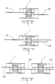
- the above mentioned application tool crimps inwardly the legs 16, 17 of the body in the shape of a "U" of connector 1 in order that the wires 2A, 2B, 2C to be spliced are urged into the contact slots 9A, 9B and 10A, 10B with the help of the positioner rods 11A, 11B.
- the metallic small tongues 6, 7, 8 break through the insulator of the wire until touching the wire itself and accomplish the electrical connection.
- the same connector 1 can be used to make splices of wires of different gauges as illustrated in Figures 6, 7 and 8.
- the present invention discloses a micro-connector, which splices telephone cables, that is of simple design but is effective and of low cost.
- the application of the connector is performed by means of an automatic tool 31 which will now be described in detail.
- FIG. 9 An automatic tool 21 for application of connectors of the prior art is illustrated in Figures 9 and 10, and presents a central cut system 29, i.e., the wires are positioned in front of each other after cutting. Additionally, said tools present an angular movement of crimping of connectors and a pressing power system of connectors which uses a cam, that is, an operating handle 23 of 360 degrees of rotation.
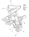
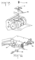
- the application tool 31 of the present invention is provided with a cut system which cuts by the ends 39, i.e., the wires are positioned side by side after the cutting. Furthermore, said tool 31 presents a horizontal movement of crimping of connectors 1, which are in the form of a micro-connector strip 32, and a pressing power system of micro-connectors which uses an operating lever 33.
- the automatic tool 31 for application of micro-connectors strip 32 has an operating handle 33, one fixed die which is an anvil 34 and one movable die which is a crimper 35, wire supports 36 for the wires to be spliced, a feed knob 37 for feeding the reeled micro-connectors and a transport catch 38 to transport the strip of micro-connectors.
- the operating handle operates the application tool 31.
- One complete forward and reverse motion is equal to one complete crimp cycle of a micro-connector.
- the operating handle 33 further has a spring which automatically returns the operating lever 33 to the starting position to crimp the next micro-connector of the strip of micro-connectors 32.
- the anvil 34 and the crimper 35 crimp the micro-connectors, i.e., the application tool 31 applies the micro-connectors to the wires by crimping them between the anvil 34 and crimper 35.
- the wire supports 36 located in the side ends of the application tool 31, position and hold the wires in the crimpers 34 and 35.
- Two cutting blades 45 to cut the wires are secured in the sides of the application tool, which cut the wire ends against the sides of the crimper 35 when it advances.
- Two blades 39 for cutting the micro-connectors 32 of the strip are secured by means of a screw 40 and a cover 41 in the anvil 34.
- a feed knob 37 which can rotate clockwise or anticlockwise, rotates a feed sprocket forward or backward in order that the micro-connectors strip 32 forward to start the application of micro-connectors or backwards to remove the strip of micro-connectors 32 of the application tool 31.
- the application tool 31 of the present invention further has a transport catch 38 which automatically advances feed sprocket when the operating handle 33 is pushed backward.
- micro-connector strip 32 In order to join the wires using a micro-connector strip 32 and the application tool 31 of the present invention is necessary, in first place, to insert micro-connector strip 32 in the application tool 31, as follows:
- the automatic tool for application of micro-connectors 1 can be used for splicing telephone cables using micro-connectors strip.
- micro-connector is provided with two different slot sizes, which allows it to cover all wire ranges indicated for this type of connector.
- the micro-connector of the present invention is a low cost connector which offers economical advantages in relation to the connectors of prior art.
- the automatic tool of the present invention provides uniform and high quality connections which meet all requirements of electrical conductivity, isolation, mechanical resistance and compaction.
- the tool includes wire supports which position and hold wires in the crimpers and a wire cut system which cuts the wires by the ends arranging them side by side after the cut. This permits the use of the reduced size micro-connectors.
Landscapes
- Engineering & Computer Science (AREA)
- Manufacturing & Machinery (AREA)
- Manufacturing Of Electrical Connectors (AREA)
- Connections By Means Of Piercing Elements, Nuts, Or Screws (AREA)
- Connections Effected By Soldering, Adhesion, Or Permanent Deformation (AREA)
- Multi-Conductor Connections (AREA)
Applications Claiming Priority (4)
| Application Number | Priority Date | Filing Date | Title |
|---|---|---|---|
| BR9302783 | 1993-07-07 | ||
| BR9302783A BR9302783A (pt) | 1993-07-07 | 1993-07-07 | Micro-conector |
| BR9303027 | 1993-07-28 | ||
| BR9303027A BR9303027A (pt) | 1993-07-28 | 1993-07-28 | Ferramenta automática para aplicação de micro-conector |
Publications (2)
| Publication Number | Publication Date |
|---|---|
| EP0633623A2 true EP0633623A2 (fr) | 1995-01-11 |
| EP0633623A3 EP0633623A3 (fr) | 1996-06-05 |
Family
ID=25664571
Family Applications (1)
| Application Number | Title | Priority Date | Filing Date |
|---|---|---|---|
| EP94304349A Ceased EP0633623A3 (fr) | 1993-07-07 | 1994-06-16 | Microconnecteur et outil automatique pour son application. |
Country Status (9)
| Country | Link |
|---|---|
| EP (1) | EP0633623A3 (fr) |
| JP (1) | JPH0729617A (fr) |
| KR (1) | KR950004637A (fr) |
| CN (1) | CN1039759C (fr) |
| AU (1) | AU673730B2 (fr) |
| CA (1) | CA2126041A1 (fr) |
| CZ (1) | CZ161594A3 (fr) |
| HU (1) | HUT68110A (fr) |
| PL (1) | PL304058A1 (fr) |
Cited By (1)
| Publication number | Priority date | Publication date | Assignee | Title |
|---|---|---|---|---|
| WO2003100921A1 (fr) * | 2002-05-21 | 2003-12-04 | Tyco Electronics Corporation | Jonction de fil isolee |
Families Citing this family (1)
| Publication number | Priority date | Publication date | Assignee | Title |
|---|---|---|---|---|
| JP2015207353A (ja) * | 2014-04-17 | 2015-11-19 | Smk株式会社 | 電線用コネクタ |
Family Cites Families (10)
| Publication number | Priority date | Publication date | Assignee | Title |
|---|---|---|---|---|
| US3355698A (en) * | 1965-04-28 | 1967-11-28 | Amp Inc | Electrical connector |
| US3436820A (en) * | 1965-11-23 | 1969-04-08 | Amp Inc | Method of making electrical connections |
| US3444312A (en) * | 1967-02-01 | 1969-05-13 | Amp Inc | Electrical connections for pairs of conductors |
| US3826861A (en) * | 1969-02-05 | 1974-07-30 | Utilux Pty Ltd | Terminal connectors for insulated conductors |
| US3611262A (en) * | 1969-02-06 | 1971-10-05 | Amp Inc | Electrical connector having integral wire severing means |
| AT326748B (de) * | 1973-07-13 | 1975-12-29 | Amp Inc | Vorrichtung zum trennen elektrischer verbinder von tragstreifen und zum andrucken der getrennten verbinder an drahte |
| US4464541A (en) * | 1983-03-21 | 1984-08-07 | Amp Incorporated | Flame retardant preinsulated electrical connector |
| US4714801A (en) * | 1984-06-14 | 1987-12-22 | Amp Incorporated | Sealant composition |
| GB8703551D0 (en) * | 1987-02-16 | 1987-03-25 | Amp Great Britain | Electrical terminal |
| US5110387A (en) * | 1988-07-29 | 1992-05-05 | Amp Incorporated | Method for laminating polymer films |
-
1994
- 1994-05-27 AU AU63404/94A patent/AU673730B2/en not_active Ceased
- 1994-06-16 CA CA002126041A patent/CA2126041A1/fr not_active Abandoned
- 1994-06-16 EP EP94304349A patent/EP0633623A3/fr not_active Ceased
- 1994-06-21 HU HU9401861A patent/HUT68110A/hu unknown
- 1994-06-30 PL PL94304058A patent/PL304058A1/xx unknown
- 1994-07-04 CZ CZ941615A patent/CZ161594A3/cs unknown
- 1994-07-05 KR KR1019940015965A patent/KR950004637A/ko not_active Ceased
- 1994-07-06 CN CN94108266A patent/CN1039759C/zh not_active Expired - Fee Related
- 1994-07-07 JP JP6179537A patent/JPH0729617A/ja active Pending
Cited By (1)
| Publication number | Priority date | Publication date | Assignee | Title |
|---|---|---|---|---|
| WO2003100921A1 (fr) * | 2002-05-21 | 2003-12-04 | Tyco Electronics Corporation | Jonction de fil isolee |
Also Published As
| Publication number | Publication date |
|---|---|
| KR950004637A (ko) | 1995-02-18 |
| CZ161594A3 (en) | 1995-01-18 |
| CN1039759C (zh) | 1998-09-09 |
| CN1105152A (zh) | 1995-07-12 |
| HU9401861D0 (en) | 1994-09-28 |
| HUT68110A (en) | 1995-05-29 |
| AU673730B2 (en) | 1996-11-21 |
| PL304058A1 (en) | 1995-01-09 |
| JPH0729617A (ja) | 1995-01-31 |
| CA2126041A1 (fr) | 1995-01-08 |
| EP0633623A3 (fr) | 1996-06-05 |
| AU6340494A (en) | 1995-01-19 |
Similar Documents
| Publication | Publication Date | Title |
|---|---|---|
| US4136440A (en) | Electrical harness fabrication method and apparatus | |
| US4065199A (en) | Flat cable wiring harness and method of producing same | |
| US3525107A (en) | Terminal crimping,wirecutting and insulation stripping tool | |
| EP2169771B1 (fr) | Fixation de terminal, chaîne de fixation de terminal, câble de fixation de terminal, son dispositif de traitement et son procédé de connexion | |
| EP0597579A2 (fr) | Connecteur d'interconnexion pour câbles coaxiaux | |
| US3668301A (en) | Means and methods of joining conductors | |
| US11146033B2 (en) | Multicore cable manufacturing method | |
| US6254430B1 (en) | Coaxial connector | |
| US5484305A (en) | Micro-connector and automated tool for application thereof | |
| JPH04337262A (ja) | 絶縁穿孔導電端子 | |
| EP0626101B1 (fr) | Connecteur de cables | |
| EP0475319A2 (fr) | Connecteur électrique | |
| US3431621A (en) | Apparatus for connecting corresponding wires of pairs of wires to each other | |
| US5120241A (en) | Miniature electrical connector | |
| EP0633623A2 (fr) | Microconnecteur et outil automatique pour son application | |
| US4214805A (en) | Methods of joining conductors | |
| US3594900A (en) | Method and apparatus for connecting pairs of conductors | |
| EP0429961B1 (fr) | Connecteur pour câble multiconducteur et procédé de branchement | |
| US3555672A (en) | High speed semiautomatic termination of coaxial cable | |
| US3577119A (en) | Electrical connectors on a carrier strip | |
| US3986256A (en) | Adapter for positioning multi-conductor cable and electrical connector | |
| US3675188A (en) | Multiple cold crimp sleeve plug and socket | |
| JPH02214405A (ja) | 多芯電気ケーブル導線の剥離と終端処理の為の装置 | |
| US4169645A (en) | Means and methods of joining conductors | |
| JPS62256392A (ja) | ケ−ブル端末処理装置及びケ−ブル端末処理方法 |
Legal Events
| Date | Code | Title | Description |
|---|---|---|---|
| PUAI | Public reference made under article 153(3) epc to a published international application that has entered the european phase |
Free format text: ORIGINAL CODE: 0009012 |
|
| AK | Designated contracting states |
Kind code of ref document: A2 Designated state(s): DE ES FR GB IT NL SE |
|
| PUAL | Search report despatched |
Free format text: ORIGINAL CODE: 0009013 |
|
| AK | Designated contracting states |
Kind code of ref document: A3 Designated state(s): DE ES FR GB IT NL SE |
|
| 17P | Request for examination filed |
Effective date: 19961122 |
|
| 17Q | First examination report despatched |
Effective date: 19971024 |
|
| GRAG | Despatch of communication of intention to grant |
Free format text: ORIGINAL CODE: EPIDOS AGRA |
|
| STAA | Information on the status of an ep patent application or granted ep patent |
Free format text: STATUS: THE APPLICATION HAS BEEN REFUSED |
|
| 18R | Application refused |
Effective date: 19981218 |